EP2204502A2 - Hydraulischer Brecher - Google Patents
Hydraulischer Brecher Download PDFInfo
- Publication number
- EP2204502A2 EP2204502A2 EP09179286A EP09179286A EP2204502A2 EP 2204502 A2 EP2204502 A2 EP 2204502A2 EP 09179286 A EP09179286 A EP 09179286A EP 09179286 A EP09179286 A EP 09179286A EP 2204502 A2 EP2204502 A2 EP 2204502A2
- Authority
- EP
- European Patent Office
- Prior art keywords
- hydraulic
- distal
- hydraulic hoses
- crusher
- hoses
- Prior art date
- Legal status (The legal status is an assumption and is not a legal conclusion. Google has not performed a legal analysis and makes no representation as to the accuracy of the status listed.)
- Granted
Links
Images


Classifications
-
- E—FIXED CONSTRUCTIONS
- E02—HYDRAULIC ENGINEERING; FOUNDATIONS; SOIL SHIFTING
- E02F—DREDGING; SOIL-SHIFTING
- E02F3/00—Dredgers; Soil-shifting machines
- E02F3/04—Dredgers; Soil-shifting machines mechanically-driven
- E02F3/28—Dredgers; Soil-shifting machines mechanically-driven with digging tools mounted on a dipper- or bucket-arm, i.e. there is either one arm or a pair of arms, e.g. dippers, buckets
- E02F3/36—Component parts
- E02F3/3604—Devices to connect tools to arms, booms or the like
- E02F3/3677—Devices to connect tools to arms, booms or the like allowing movement, e.g. rotation or translation, of the tool around or along another axis as the movement implied by the boom or arms, e.g. for tilting buckets
- E02F3/3681—Rotators
-
- E—FIXED CONSTRUCTIONS
- E02—HYDRAULIC ENGINEERING; FOUNDATIONS; SOIL SHIFTING
- E02F—DREDGING; SOIL-SHIFTING
- E02F3/00—Dredgers; Soil-shifting machines
- E02F3/04—Dredgers; Soil-shifting machines mechanically-driven
- E02F3/28—Dredgers; Soil-shifting machines mechanically-driven with digging tools mounted on a dipper- or bucket-arm, i.e. there is either one arm or a pair of arms, e.g. dippers, buckets
- E02F3/36—Component parts
- E02F3/3604—Devices to connect tools to arms, booms or the like
- E02F3/3609—Devices to connect tools to arms, booms or the like of the quick acting type, e.g. controlled from the operator seat
- E02F3/3654—Devices to connect tools to arms, booms or the like of the quick acting type, e.g. controlled from the operator seat with energy coupler, e.g. coupler for hydraulic or electric lines, to provide energy to drive(s) mounted on the tool
-
- E—FIXED CONSTRUCTIONS
- E02—HYDRAULIC ENGINEERING; FOUNDATIONS; SOIL SHIFTING
- E02F—DREDGING; SOIL-SHIFTING
- E02F3/00—Dredgers; Soil-shifting machines
- E02F3/04—Dredgers; Soil-shifting machines mechanically-driven
- E02F3/28—Dredgers; Soil-shifting machines mechanically-driven with digging tools mounted on a dipper- or bucket-arm, i.e. there is either one arm or a pair of arms, e.g. dippers, buckets
- E02F3/36—Component parts
- E02F3/3604—Devices to connect tools to arms, booms or the like
- E02F3/3677—Devices to connect tools to arms, booms or the like allowing movement, e.g. rotation or translation, of the tool around or along another axis as the movement implied by the boom or arms, e.g. for tilting buckets
-
- E—FIXED CONSTRUCTIONS
- E02—HYDRAULIC ENGINEERING; FOUNDATIONS; SOIL SHIFTING
- E02F—DREDGING; SOIL-SHIFTING
- E02F3/00—Dredgers; Soil-shifting machines
- E02F3/04—Dredgers; Soil-shifting machines mechanically-driven
- E02F3/96—Dredgers; Soil-shifting machines mechanically-driven with arrangements for alternate or simultaneous use of different digging elements
- E02F3/965—Dredgers; Soil-shifting machines mechanically-driven with arrangements for alternate or simultaneous use of different digging elements of metal-cutting or concrete-crushing implements
-
- E—FIXED CONSTRUCTIONS
- E02—HYDRAULIC ENGINEERING; FOUNDATIONS; SOIL SHIFTING
- E02F—DREDGING; SOIL-SHIFTING
- E02F9/00—Component parts of dredgers or soil-shifting machines, not restricted to one of the kinds covered by groups E02F3/00 - E02F7/00
- E02F9/20—Drives; Control devices
- E02F9/22—Hydraulic or pneumatic drives
- E02F9/2264—Arrangements or adaptations of elements for hydraulic drives
- E02F9/2275—Hoses and supports therefor and protection therefor
Definitions
- the present invention relates to a hydraulic crusher attached to a distal section of an arm of a working machine such as a hydraulic excavator, and used for demolition etc. of a structure.
- a hydraulic crusher typically includes a pair of crushing arms that crush an object to be crushed, a crusher body a distal section of which supports the crushing arms in an openable and closable manner around pivots, and a pair of hydraulic cylinders coupled to proximal section of the crusher body and to the crushing arms respectively rotatably around pivots.
- Hydraulic hoses that connect ports at the proximal section of the crusher body with ports at proximal sections of the hydraulic cylinders are formed between the distal section and the proximal section of the crusher body to prevent the hydraulic hoses from being damaged because of collision with scattering crushed pieces.
- major parts of the hydraulic hoses are housed in a hollow portion surrounded by cover plates (for example, see Japanese Unexamined Patent Application Publication Nos. 2004-68393 and 2008-18364 ).
- the crushing arms are opened when piston rods of the hydraulic cylinders are accommodated in cylinder bodies, and the crushing arms are closed when the piston rods protrude from the cylinder bodies.
- the concrete structure etc. gripped by the open crushing arms is crushed by the crushing arms when the crushing arms are closed.
- the hydraulic crusher attached to the distal section of the arm of the working machine is very compact.
- the hydraulic hose is bent with a small bend radius in the hollow portion of the crusher body. The hydraulic hose may be damaged.
- hydraulic hose since the hydraulic hose is housed in the hollow portion of the crusher body in a constrained manner, it may be difficult to replace a damaged hydraulic hose with new one.
- a hydraulic crusher shown in Fig. 8 may be conceived.
- the hydraulic crusher effectively uses the hollow portion of the crusher body.
- Fig. 8 does not illustrate a frame or a part of a cover member which define a crusher body 105.
- hydraulic hoses that connect the crusher body 105 with hydraulic cylinders 103 are divided into first hydraulic hoses 107, 117, 127, and 137 which are connected to ports (not shown) of the crusher body 105, and second hydraulic hoses 109, 119, 129, and 139 which are connected to ports (not shown) of the hydraulic cylinders 103.
- a joint block 131 is provided in a distal section of a hollow portion 165 of the crusher body 105. Distal sections of the first hydraulic hoses 107, 117, 127, and 137 are connected to distal sections of the second hydraulic hoses 109, 119, 129, and 139.
- the hydraulic hoses that connect the crusher body 105 with the hydraulic cylinders 103 are divided into the first hydraulic hoses 107, 117, 127, and 137 and the second hydraulic hoses 109, 119, 129, and 139.
- the first and second hydraulic hoses 107, 117, 127, and 137 and 109, 119, 129, and 139 each can be easily replaced with new one.
- the distal sections of the first hydraulic hoses 107, 117, 127, and 137 are connected to the distal sections of the second hydraulic hoses 109, 119, 129, and 139 through the joint block 131.
- first and second hydraulic hoses 107, 117, 127, and 137 and 109, 119, 129, and 139 do not have to be bent with a small bend radius.
- the first and second hydraulic hoses 107, 117, 127, and 137 and 109, 119, 129, and 139 can be prevented from being damaged.
- the first hydraulic hoses 107, 117, 127, and 137 are fixed, the first hydraulic hoses 107, 117, 127, and 137 are not moved although the crushing arms 111 are opened and closed.
- the length of the second hydraulic hoses 109, 119, 129, and 139 is a length that prevents the second hydraulic hoses 109, 119, 129, and 139 from interfering with the first hydraulic hoses 107, 117, 127, and 137, more particularly, a length that prevents the second hydraulic hoses 109, 119, 129, and 139 from being loosened and curved even when the crushing arms 111 are closed, the first and second hydraulic hoses 107, 117, 127, and 137, and 109, 119, 129, and 139 can be prevented from being rubbed on one another and hence being damaged.
- the other problems may come up as follows.
- the length of the second hydraulic hoses 109, 119, 129, and 139 is limited so as not to be loosened and curved even when the crushing arms 111 are closed.
- the second hydraulic hoses 109, 119, 129, and 139 are pulled and become tensed between the hydraulic cylinders 103 and the joint block 131.
- the second hydraulic hoses 109, 119, 129, and 139 tend to be damaged.
- the second hydraulic hoses 109, 119, 129, and 139 only have small flexibility because the opposite ends of the second hydraulic hoses 109, 119, 129, and 139 are fixed.
- crushed pieces or the like may be stacked between the cylinder bodies 113 and the second hydraulic hoses 109, 119, 129, and 139.
- the second hydraulic hoses 109, 119, 129, and 139 may be damaged.
- An object of the present invention is to provide a hydraulic crusher attached to a distal section of an arm of a working machine, the hydraulic crusher which can prevent a hydraulic hose from being damaged and facilitate replacement of the hydraulic hose.
- a first hydraulic hose which is connected to a port of a crusher body, is connected with a second hydraulic hose, which is connected to a port of a hydraulic cylinder, through joint means provided in a hollow portion of the crusher body.
- the hydraulic hoses can be prevented from being bent with an excessively small bend radius. Also, by moving the joint means in the longitudinal direction, flexibility of the hydraulic hoses can be maintained.
- a hydraulic crusher is detachably attached to a distal section of an arm of a working machine.
- the hydraulic crusher includes a pair of crushing arms, a crusher body, a pair of hydraulic cylinders, a plurality of first hydraulic hoses, a plurality of second hydraulic hoses, and joint means.
- the crushing arms are configured to grip and crush an object to be crushed.
- a proximal section of the crusher body is attached to the distal section of the arm of the working machine.
- the proximal section of the crusher body has ports.
- a distal section of the crusher body supports the crushing arms in an openable and closable manner around pivots.
- the crusher body has a hollow portion between the distal section and the proximal section of the crusher body.
- the hollow portion extends in a longitudinal direction defined by connecting the distal section with the proximal section of the crusher body.
- Proximal sections of the hydraulic cylinders are coupled to the proximal section of the crusher body outside the hollow portion rotatably around pivots.
- the proximal sections of the hydraulic cylinders have ports.
- Distal sections of the hydraulic cylinders are respectively coupled to the crushing arms rotatably around pivots.
- the first hydraulic hoses have proximal caps connected to the ports at the proximal section of the crusher body.
- the first hydraulic hoses extend toward a distal side in the longitudinal direction in the hollow portion.
- the second hydraulic hoses have proximal caps connected to the ports at the proximal sections of the hydraulic cylinders.
- the second hydraulic hoses extend into the hollow portion and then extend toward the distal side in the longitudinal direction while being curved.
- the joint means is movable in the longitudinal direction in the hollow portion.
- the joint means connects distal sections of the first hydraulic hoses with distal sections of the second hydraulic hoses.
- the hydraulic hoses that connect the crusher body with the hydraulic cylinders are divided into the first hydraulic hoses connected to the ports at the proximal section of the crusher body, and the second hydraulic hoses connected to the ports at the proximal sections of the hydraulic cylinders.
- the distal sections of the first hydraulic hoses are connected to the distal sections of the second hydraulic hoses through the joint means.
- the second hydraulic hoses are pulled in a direction in which the hydraulic cylinders are opened by following the movement of the hydraulic cylinders.
- the force that pulls the second hydraulic hoses in the direction in which the hydraulic cylinders are opened is converted into the force that pulls the second hydraulic hoses toward the proximal side in the longitudinal direction.
- the second hydraulic hoses are connected to the joint means that is movable in the longitudinal direction in the hollow portion, even when the second hydraulic hoses are pulled toward the proximal side in the longitudinal direction, the second hydraulic hoses do not become tensed between the hydraulic cylinders and the joint means.
- the distal sections of the second hydraulic hoses are connected to the joint means that is movable in the longitudinal direction, and hence the second hydraulic hoses are flexible, when the hydraulic cylinders are contracted, crushed pieces or the like do not tend to be stacked between the hydraulic cylinders and the second hydraulic hoses connected thereto. Even if the crushed pieces or the like are stacked between the hydraulic cylinders and the second hydraulic hoses, the second hydraulic hoses do not tend to be damaged because of the flexibility thereof.
- the second hydraulic hoses connected to the ports of the hydraulic cylinders may be more frequently damaged as compared with the first hydraulic hoses connected to the ports of the crusher body. However, since the distal sections of the second hydraulic hoses are connected to the joint means that is movable in the longitudinal direction, the replacement of the second hydraulic hoses can be facilitated.
- the joint means may bind the distal sections and/or portions near the distal sections of the second hydraulic hoses such that the distal sections of the second hydraulic hoses are separated from the distal sections of the first hydraulic hoses by a predetermined distance.
- the pair of hydraulic cylinders symmetrically rotate around pivots of the crusher body by following the opening and closing operation of the pair of crushing arms.
- the hydraulic hoses connected to the hydraulic cylinders are moved by following the hydraulic cylinders.
- the hydraulic hoses may be rubbed on one another and damaged.
- the joint means binds the distal sections and/or the portions near the distal sections of the second hydraulic hoses such that the distal sections of the second hydraulic hoses are separated from the distal sections of the first hydraulic hoses by a predetermined distance. Accordingly, the second hydraulic hoses can be prevented from being irregularly moved as a result of the movement of the hydraulic cylinders. That is, the joint means suppresses the movement of the second hydraulic hoses pulled by the hydraulic cylinders.
- the joint means is moved toward the proximal side in the longitudinal direction without being inclined, the first hydraulic hoses connected to the joint means are not excessively bent or twisted.
- the first hydraulic hoses can be uniformly bent.
- the first hydraulic hoses can be prevented from being too close to the second hydraulic hoses.
- the first hydraulic hoses can be prevented from being rubbed on and damaged by the second hydraulic hoses.
- the joint means may more preferably bind the distal sections and/or portions near the distal sections of the second hydraulic hoses such that the second hydraulic hoses are separated from one another.
- the joint means binds the distal sections and/or the portions near the distal sections of the second hydraulic hoses such that the second hydraulic hoses are separated from one another.
- the second hydraulic hoses can be prevented from being damaged because the second hydraulic hoses repeatedly contact one another and are repeatedly separated from one another by following the opening and closing operation of the crushing arms.
- the joint means may be disconnected from the crusher body.
- the joint means is disconnected from the crusher body, for example, an impact due to collision between the crushing arms and an object to be crushed can be prevented from being directly transmitted to the joint means. Even if the crushed pieces hit the member defining the hollow portion of the crusher body, and the member is damaged, the joint means tends to avoid the damage. Accordingly, the joint means can be prevented from being broken, and hence the hydraulic hoses can be further reliably prevented from being damaged.
- the first hydraulic hoses may have distal caps coupled to the joint means rotatably relative to the joint means.
- the distal caps of the first hydraulic hoses are coupled to the joint means rotatably relative to the joint means.
- the first hydraulic hoses can be prevented from being twisted. Accordingly, although the opening and closing operation of the crushing arms and the movement of the joint means in the longitudinal direction are carried out repeatedly, the first hydraulic hoses can be reliably prevented from being damaged.
- the joint means may include elbow-shaped distal caps of the second hydraulic hoses, a clamp that binds the distal caps and/or portions near the distal caps of the second hydraulic hoses, and connectors to which the distal caps of the second hydraulic hoses are connected in a direction orthogonal to the longitudinal direction, and to which distal caps of the first hydraulic hoses are connected from the proximal side in the longitudinal direction.
- the joint means includes general parts such as the elbow-shaped distal caps of the second hydraulic hoses, the clamp that binds the distal caps and/or the portions near the distal caps, and the connectors having the elbow-shaped through holes.
- the joint means can be provided easily with low cost.
- the clamp may have a plurality of through holes separated from one another in a plane orthogonal to the longitudinal direction and extending in the longitudinal direction.
- the distal caps and/or the portions near the distal caps of the second hydraulic hoses may be fitted into the through holes.
- the simply structured clamp can bind the distal caps and/or the portions near the distal caps of the second hydraulic hoses.
- the clamp is used when the joint means binds the distal sections and/or portions near the distal sections of the second hydraulic hoses such that the second hydraulic hoses are separated from one another, the distal sections of the second hydraulic hoses can be separated from the distal sections the first hydraulic hoses by a predetermined distance, and the second hydraulic hoses can be separated from one another.
- Fig. 1 illustrates a hydraulic crusher attached to a hydraulic excavator.
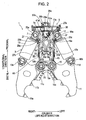
- Fig. 2 is a front view showing the hydraulic crusher when crushing arms are open.
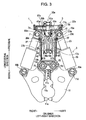
- Fig. 3 is a front view showing the hydraulic crusher when the crushing arms are closed.
- Fig. 4 is a side view showing the hydraulic crusher when the crushing arms are closed.
- Fig. 5 is a sectional view taken along line V-V in Fig. 2 .
- Figs. 2 to 4 do not illustrate a part of a cover plate 55 or an attaching bracket 25, and Fig. 4 does not illustrate part of crushing arms 11 or a hydraulic cylinder 3.
- a hydraulic crusher 1 of this embodiment is attached to a distal section of an arm 21 of the hydraulic excavator through an attaching bracket 25.
- the hydraulic crusher 1 can be detachably attached to the arm 21, and hence the hydraulic crusher 1 can be replaced with a head attachment such as a bucket.
- the hydraulic crusher 1 includes a crusher body 5; a pair of crushing arms 11 supported at a distal section of the crusher body 5; a pair of hydraulic cylinders 3 respectively coupled to the crushing arms 11 and coupled to a proximal section of the crusher body 5; four first hydraulic hoses 7, 17, 27, and 37 proximal sections of which are connected to the crusher body 5; four second hydraulic hoses 9, 19, 29, and 39 proximal sections of which are connected to the hydraulic cylinders 3; a clamp 31 that binds the second hydraulic hoses 9, 19, 29, and 39; and four distal connectors 41b, 51b, 61b, and 71b that connect distal sections of the first hydraulic hoses 7, 17, 27, and 37 respectively with distal sections of the second hydraulic hoses 9, 19, 29, and 39.
- the crusher body 5 includes a supporting bracket 15 (the distal section of the crusher body 5) that supports the pair of crushing arms 11 in an openable and closable manner by arm coupling pins 75; the attaching bracket 25 (the proximal section of the crusher body 5) that is attached to the distal section of the arm 21 of the hydraulic excavator by a first coupling pin 85a; a swivel unit 35 provided at the distal side of the attaching bracket 25; a frame 45 extending in the longitudinal direction (a direction defined by connecting the supporting bracket 15 with the swivel unit 35) and coupling the swivel unit 35 with the supporting bracket 15; and a cover plate 55 attached to the frame 45.
- the extending direction of the arm coupling pins 75 represents the crusher front-rear direction
- the direction orthogonal to the longitudinal direction and to the crusher front-rear direction represents the crusher left-right direction.
- the supporting bracket 15 includes side plates 15a and a supporting plate 15b.
- the side plates 15a are arranged to face each other in the crusher front-rear direction with the pair of crushing arms 11 interposed therebetween.
- Each of the side plates 15a has an almost figure-of-eight shape and has two bosses 15c arranged side by side in the crusher left-right direction.
- the supporting plate 15b couples proximal ends in the longitudinal direction of the side plates 15a with each other.
- the supporting bracket 15 has an almost C shape when viewed in the crusher left-right direction.
- the attaching bracket 25 is secured to a proximal end in the longitudinal direction of the swivel unit 35 by bolts.
- the attaching bracket 25 includes side plates 25a arranged to face each other with the distal section of the arm 21 of the hydraulic excavator interposed therebetween.
- Each of the side plates 25a has first and second bosses 25b and 25c.
- the attaching bracket 25 is rotatably supported by the distal section of the arm 21 of the hydraulic excavator by the first coupling pin 85a that is inserted through the first bosses 25b.
- the attaching bracket 25 is coupled to a linkage 21a provided at the arm 21 of the hydraulic excavator by a second coupling pin 85b that is inserted through the second bosses 25c.
- the hydraulic crusher 1 rotates upward and downward around the first coupling pin 85a by following the movement of the linkage 21a.
- the hydraulic crusher 1 can grip an object to be crushed located at a position above or below the arm 21.
- the swivel unit 35 has a rotary bearing and hence is rotatable relative to the attaching bracket 25.
- the frame 45 provided at the distal side in the longitudinal direction of the swivel unit 35 rotates around the rotation axis of the swivel unit 35.
- the swivel unit 35 includes a swivel joint 35a arranged in the swivel unit 35.
- the swivel joint 35a connects hydraulic hoses 21b (more specifically, hydraulic hoses located near the hydraulic cylinders 3 with respect to a speed increasing valve (see Fig. 6 )) with the first hydraulic hoses 7, 17, 27, and 37.
- the hydraulic hoses 21b are provided at the arm 21 of the working machine and hence included in a stationary section.
- the first hydraulic hoses 7, 17, 27, and 37 are included in a movable section.
- a rotary cylinder 35b is provided in the movable section with respect to the swivel joint 35a.
- the rotary cylinder 35b has four hydraulic ports 35c, 35d, 35e, and 35f (ports provided at the proximal section of the crusher body 5 (see Fig. 6 )), through which hydraulic oil is supplied to or drained from the hydraulic cylinders 3.
- the frame 45 is a hollow truncated square pyramid that is rectangular in front view (when viewed in the crusher front-rear direction) and that is trapezoidal in side view (when viewed in the crusher left-right direction) in such a manner as the width of the frame 45 decreases toward the distal side.
- the frame 45 has therein a hollow portion 65 extending in the longitudinal direction.
- the frame 45 has front, rear, left, and right side surfaces each having an opening 45b for cleaning of the inside of the hollow portion 65 and for maintenance of piping.
- Each opening 45b is covered with the cover plate 55.
- the cover plate 55 is secured to the frame 45 by bolts. Thus, for example, scattered concrete pieces (crushed pieces) can be prevented from entering the hollow portion 65.
- bosses 45a are provided at both left and right side surfaces of the frame 45. On either side, the bosses 45a face each other in the crusher front-rear direction with corresponding one of proximal bosses 23a (which will be described later) of the hydraulic cylinders 3 interposed therebetween.
- the crushing arms 11 grip and crush an object to be crushed, such as a concrete structure.
- the crushing arms 11 are rotatably supported by the crusher body 5 because inner bosses 11e provided at the proximal end in the longitudinal direction are respectively coupled to the bosses 15c of the supporting bracket 15 by arm coupling pins 75.
- the crushing arms 11 rotate in opposite directions around the arm coupling pins 75.
- the pair of crushing arms 11 are opened or closed in the crusher left-right direction.
- the crushing arms 11 have distal teeth 11a and 11b at distal sections and center sections in the longitudinal direction of the inner edges in the crusher left-right direction of the crushing arms 11 (at the edge at which the crushing arm 11 overlaps with the other crushing arm 11 when being closed).
- the distal teeth 11a and 11b firmly grip an object to be crushed.
- the crushing arms 11 have cutters 11c at proximal sections in the longitudinal direction of the crushing arms 11.
- the cutters 11c cut a reinforcing steel bar protruding from a crushed concrete structure.
- the crushing arms 11 have outer bosses 11d at proximal sections in the longitudinal direction of the outer edges in the crusher left-right direction of the crushing arms 11.
- the hydraulic cylinders 3 are coupled to the outer bosses 11d.
- the hydraulic cylinders 3 each include a cylinder body 13, a piston rod 23, and a piston 33. Since both hydraulic cylinders 3 have similar structures, one of the hydraulic cylinders 3 will be described below.
- the cylinder body 13 has a cylindrical shape with the top and bottom.
- the cylinder body 13 has two distal bosses 13a at a distal section of the cylinder body 13.
- the distal bosses 13a face each other in the crusher front-rear direction with the outer boss 11d of the corresponding crushing arm 11 interposed therebetween.
- the piston 33 is arranged in the cylinder body 13 slidably along the axis of the cylinder body 13.
- the piston 33 divides the inner space of the cylinder body 13 into a head-side oil chamber 3b located at the distal side and a rod-side oil chamber 3a located at the proximal side.
- the piston rod 23 is slidably fitted into the cylinder body 13.
- the distal section of the piston rod 23 is coupled to the piston 33.
- the proximal section of the piston rod 23 has a proximal boss 23a.
- the proximal boss 23a is coupled to the corresponding boss 45a of the frame 45.
- the piston rod 23 has a head-side hydraulic port 23b and a rod-side hydraulic port 23c (a port provided at the proximal section of the hydraulic cylinder 3) near the proximal boss 23a.
- the head-side hydraulic port 23b communicates with the head-side oil chamber 3b through a first oil channel (not shown) formed in the piston rod 23, and also communicates with the rod-side oil chamber 3a through a second oil channel (not shown) formed in the piston rod 23.
- the proximal bosses 23a (the proximal sections) of the hydraulic cylinders 3 are coupled to the bosses 45a of the frame 45 (the proximal section of the crusher body 5) outside the hollow portion 65 rotatably by coupling pins 95a.
- the distal bosses 13a (the distal sections) of the hydraulic cylinders 3 are coupled to the outer bosses 11d of the crushing arms 11 rotatably by coupling pins 95b.
- the first hydraulic hoses 7, 17, 27, and 37 are flexible rubber hoses.
- the first hydraulic hoses 7, 17, 27, and 37 include left and right first rod-side hydraulic hoses 7 and 17 that supply the hydraulic oil to and drain the hydraulic oil from the rod-side oil chambers 3a of the hydraulic cylinders 3; and left and right first head-side hydraulic hoses 27 and 37 that supply the hydraulic oil to and drain the hydraulic oil from the head-side oil chambers 3b of the hydraulic cylinders 3.
- the first rod-side hydraulic hoses 7 and 17 have proximal caps 7a and 17a and distal caps 7b and 17b having straight shapes (shapes without a bent portion).
- the proximal caps 7a and 17a are connected to the proximal hydraulic ports 35c and 35d provided at the swivel joint 35a (the proximal section of the crusher body 5) through proximal connectors 41a and 51a.
- the first rod-side hydraulic hoses 7 and 17 extend in the hollow portion 65 in substantially straight from the proximal connectors 41a and 51a toward the distal side in the longitudinal direction when the crushing arms 11 are open, i.e., when the hydraulic cylinders 3 are closed.
- the first head-side hydraulic hoses 27 and 37 have proximal caps 27a and 37a having bent shapes which have bent portions bent by 45 degrees; and distal caps 27b and 37b having straight shapes.
- the proximal caps 27a and 37a are connected to the distal hydraulic ports 35e and 35f provided at the swivel joint 35a through proximal connectors 61a and 71a.
- the first head-side hydraulic hoses 27 and 37 extend from the proximal connectors 61a and 71a in the hollow portion 65 in a direction inclined by about 45 degrees with respect to the longitudinal direction, are slightly curved, and then extend substantially straight toward the distal side in the longitudinal direction when the crushing arms 11 are open, i.e., when the hydraulic cylinders 3 are closed.
- the second hydraulic hoses 9, 19, 29, and 39 are flexible rubber hoses.
- the second hydraulic hoses 9, 19, 29, and 39 include left and right second rod-side hydraulic hoses 9 and 19 that supply the hydraulic oil to and drain the hydraulic oil from the rod-side oil chambers 3a of the hydraulic cylinders 3; and left and right second head-side hydraulic hoses 29 and 39 that supply the hydraulic oil to and drain the hydraulic oil from the head-side oil chambers 3b of the hydraulic cylinders 3.
- the second rod-side hydraulic hoses 9 and 19 and the second head-side hydraulic hoses 29 and 39 have proximal caps 9a, 19a, 29a, and 39a having straight shapes; and distal caps 9b, 19b, 29b, and 39b having bent shapes (elbow shapes) which have bent portions bent by 90 degrees.
- the proximal caps 9a and 19a of the second rod-side hydraulic hoses 9 and 19 are connected to the rod-side hydraulic ports 23c, which are provided at the proximal sections of the hydraulic cylinders 3, in directions orthogonal to the hydraulic cylinders 3.
- the proximal caps 29a and 39a of the second head-side hydraulic hoses 29 and 39 are connected to the head-side hydraulic ports 23b, which are provided at the proximal sections of the hydraulic cylinders 3, in the directions orthogonal to the hydraulic cylinders 3.
- the second rod-side and head-side hydraulic hoses 9, 19, 29, and 39 which are connected to the head-side and rod-side hydraulic ports 23b and 23c of the hydraulic cylinders 3 at the outside of the hollow portion 65, pass through the openings 45b formed in the left and right side surfaces of the frame 45 (proximal portions not covered with the cover plates 55), and extend into the hollow portion 65 and then toward the distal side in the longitudinal direction while being curved.
- the clamp 31 binds the distal caps 9b, 19b, 29b, and 39b of the four second hydraulic hoses 9, 19, 29, and 39 so that the distal caps 9b, 19b, 29b, and 39b are separated from the distal caps 7b, 17b, 27b, and 37b of the four first hydraulic hoses 7, 17, 27, and 37 by a predetermined distance.
- the clamp 31 is a disk-shaped rubber clamp. Referring to Fig. 5 , the clamp 31 has four through holes 31c, 31d, 31e, and 31f extending in the longitudinal direction.
- the distal caps 9b, 19b, 29b, and 39b of the second hydraulic hoses 9, 19, 29, and 39 are fitted into the through holes 31c, 31d, 31e, and 31f.
- the through holes 31c, 31d, 31e, and 31f are separated from one another in a plane orthogonal to the longitudinal direction.
- the through holes 31c, 31d, 31e, and 31f are respectively connected to notches 31g, 31h, 31i, and 31j formed at the peripheral edge of the clamp 31.
- the distal caps 9b, 19b, 29b, and 39b of the second hydraulic hoses 9, 19, 29, and 39 respectively pass through the notches 31g, 31h, 31i, and 31j and then are respectively fitted into the through holes 31c, 31d, 31e, and 31f.
- the four second hydraulic hoses 9, 19, 29, and 39 are separated from one another by a distance that prevents the second hydraulic hoses 9, 19, 29, and 39 from being rubbed on one another.
- the clamp 31 has an annular groove in the outer peripheral surface of the clamp 31 at a center portion thereof in the longitudinal direction to extend over the entire circumference thereof.
- a steel band 31a having a length adjustment screw 31b is fitted into the annular groove.
- the clamp 31 firmly binds the distal caps 9b, 19b, 29b, and 39b of the second hydraulic hoses 9, 19, 29, and 39 by clamping the steel band 31a by the length adjustment screw 31b.
- the distal connectors 41b, 51b, 61b, and 71b are substantially cubical steel connectors.
- Each of the distal connectors 41b, 51b, 61b, and 71b has connection ports in the proximal surface and a side surface, and has therein an elbow-shaped through hole to cause these connection ports to communicate with each other.
- the distal cap 7b of the right first rod-side hydraulic hose 7 is connected to the connection port in the proximal surface of the distal connector 41b located at the rear right side of the crusher.
- the distal cap 17b of the left first rod-side hydraulic hose 17 is connected to the connection port in the proximal surface of the distal connector 51b located at the front left side of the crusher.
- the distal cap 27b of the right first head-side hydraulic hose 27 is connected to the connection port in the proximal surface of the distal connector 61b located at the front right side of the crusher.
- the distal cap 37b of the left first head-side hydraulic hose 37 is connected to the connection port in the proximal surface of the distal connector 71b located at the rear left side of the crusher.
- the distal cap 9b of the right second rod-side hydraulic hose 9 is connected to the connection port in the side surface of the distal connector 41b located at the rear right side of the crusher.
- the distal cap 19b of the left second rod-side hydraulic hose 19 is connected to the connection port in the side surface of the distal connector 51b located at the front left side of the crusher.
- the distal cap 29b of the second head-side hydraulic hose 29 is connected to the connection port in the side surface of the distal connector 61b located at the front right side of the crusher.
- the distal cap 39b of the second head-side hydraulic hose 39 is connected to the connection port in the side surface of the distal connector 71b located at the rear left side of the crusher.
- the hydraulic oil flowing through the first hydraulic hoses 7, 17, 27, and 37 is sent to the second hydraulic hoses 9, 19, 29, and 39 through the through holes in the distal connectors 41b, 51b, 61b, and 71b, and then is supplied to the rod-side oil chambers 3a and the head-side oil chambers 3b of the hydraulic cylinders 3.
- both hydraulic hoses do not have to be bent with an unreasonable bend radius of a predetermined minimum radius or smaller.
- Joint means of the present invention corresponds to the distal caps 9b, 19b, 29b, and 39b of the second hydraulic hoses 9, 19, 29, and 39; the clamp 31; and the distal connectors 41b, 51b, 61b, and 71b.
- the piping structure including the joint means 9b, 19b, 29b, 39b, 31, 41b, 51b, 61b, and 71b will be described below in detail.
- the second hydraulic hoses 9, 19, 29, and 39 which are connected to the head-side and rod-side hydraulic ports 23b and 23c of the hydraulic cylinders 3 outside the hollow portion 65, enter the hollow portion 65 and extend in the hollow portion 65 toward the distal side in the longitudinal direction while being curved.
- the clamp 31 binds straight portions (portions at the proximal side in the longitudinal direction with respect to the 90-degrees-bent portions) of the distal caps 9b, 19b, 29b, and 39b of the second hydraulic hoses 9, 19, 29, and 39 at a center portion of the hollow portion 65 in the longitudinal direction.
- the distal caps 9b, 19b, 29b, and 39b of the second hydraulic hoses 9, 19, 29, and 39 bound by the clamp 31 extend outward in the directions orthogonal to the longitudinal direction to be bent at 90 degrees, are radially expanded at lower end portions of the distal caps 9b, 19b, 29b, and 39b, and are connected to the connection ports formed in the side surfaces of the distal connectors 41b, 51b, 61b, and 71b.
- the distal caps 9b, 19b, 29b, and 39b of the second hydraulic hoses 9, 19, 29, and 39; the distal connectors 41b, 51b, 61b, and 71b; and the clamp 31 (the joint means) are not connected to the crusher body 5 (disconnected state), but the distal connectors 41b, 51b, 61b, and 71b are connected to the distal caps 9b, 19b, 29b, and 39b of the second hydraulic hoses 9, 19, 29, and 39, and the clamp 31 binds the distal caps 9b, 19b, 29b, and 39b of the second hydraulic hoses 9, 19, 29, and 39.
- the distal caps 9b, 19b, 29b, and 39b of the second hydraulic hoses 9, 19, 29, and 39; the distal connectors 41b, 51b, 61b, and 71b; and the clamp 31 (the joint means) are movable as a unit in the longitudinal direction in the hollow portion 65.
- the first rod-side and head-side hydraulic hoses 7, 17, 27, and 37 which are connected to the proximal and distal hydraulic ports 35c, 35d, 35e, and 35f of the swivel joint 35a through the proximal connectors 41a, 51a, 61a, and 71a extend in the hollow portion 65 toward the distal side in the longitudinal direction.
- the distal caps 7b, 17b, 27b, and 37b of the first rod-side and head-side hydraulic hoses 7, 17, 27, and 37 are connected to the connection ports in the proximal surfaces of the distal connectors 41b, 51b, 61b, and 71b.
- the right first rod-side hydraulic hose 7 and the right first head-side hydraulic hose 27 connected to the hydraulic cylinder 3 located at the right side in the crusher left-right direction extend in the longitudinal direction between the proximal connectors 41a, 61a and the distal connectors 41b, 61b such that the right second rod-side and head-side hydraulic hoses 9, 29, which extend outside from the hollow portion 65 while being curved rightward, are interposed between the first rod-side and head-side hydraulic hoses 7 and 27 in the crusher front-rear direction.
- the left first rod-side hydraulic hose 17 and the left first head-side hydraulic hose 37 connected to the hydraulic cylinder 3 located at the left side in the crusher left-right direction extend in the longitudinal direction between the proximal connectors 51a, 71a and the distal connectors 51b, 71b such that the left second rod-side and head-side hydraulic hoses 19, 39, which extend outside from the hollow portion 65 while being curved leftward, are interposed between the first rod-side and head-side hydraulic hoses 17 and 37 in the crusher front-rear direction.
- the clamp 31 binds the distal caps 9b, 19b, 29b, and 39b of the second hydraulic hoses 9, 19, 29, and 39, and the distal caps 7b, 17b, 27b, and 37b of the first hydraulic hoses 7, 17, 27, and 37 are connected to the distal caps 9b, 19b, 29b, and 39b, the lower end portions of which are radially expanded while being bent at 90 degrees, through the distal connectors 41b, 51b, 61b, and 71b.
- the first hydraulic hoses 7, 17, 27, and 37 surround the second hydraulic hoses 9, 19, 29, and 39 with a predetermined distance interposed therebetween. Operation of First and Second Hydraulic Hoses
- the force that pulls the second hydraulic hoses 9, 19, 29, and 39 in a direction in which the hydraulic cylinders 3 are opened is converted into the force that pulls the second hydraulic hoses 9, 19, 29, and 39 toward the proximal side in the longitudinal direction.
- the second hydraulic hoses 9, 19, 29, and 39 are connected to the clamp 31 that is movable in the longitudinal direction in the hollow portion 65. Thus, even when the second hydraulic hoses 9, 19, 29, and 39 are pulled toward the proximal side in the longitudinal direction, the second hydraulic hoses 9, 19, 29, and 39 are not tensed between the hydraulic cylinders 3 and the clamp 31, but the clamp 31 is moved toward the proximal end.
- the clamp 31 binds the distal caps 9b, 19b, 29b, and 39b of the second hydraulic hoses 9, 19, 29, and 39, the second hydraulic hoses 9, 19, 29, and 39 can be prevented from being irregularly moved (irregularly bent or twisted).
- the clamp 31 is firmly fastened to the hard distal caps 9b, 19b, 29b, and 39b, the clamp 31 is moved toward the proximal side in the longitudinal direction without being inclined.
- distal caps 9b, 19b, 29b, and 39b of the second hydraulic hoses 9, 19, 29, and 39 bound by the clamp 31, as well as the distal connectors 41b, 51b, 61b, and 71b are moved toward the proximal side in the longitudinal direction without being inclined.
- the distal connectors 41b, 51b, 61b, and 71b are moved toward the proximal side in the longitudinal direction without being inclined, the first hydraulic hoses 7, 17, 27, and 37 connected to the distal connectors 41b, 51b, 61b, and 71b are uniformly bent without being excessively bent or twisted.
- the hydraulic hoses that connect the crusher body 5 with the hydraulic cylinders 3 include the first hydraulic hoses 7, 17, 27, and 37 that are connected to the proximal and distal hydraulic ports 35c, 35d, 35e, and 35f of the swivel joint 35a; and the second hydraulic hoses 9, 19, 29, and 39 that are connected to the head-side and rod-side hydraulic ports 23b and 23c of the hydraulic cylinders 3. Also, the distal caps 7b, 17b, 27b, and 37b of the first hydraulic hoses 7, 17, 27, and 37 are connected to the distal caps 9b, 19b, 29b, and 39b of the second hydraulic hoses 9, 19, 29, and 39 through the distal connectors 41b, 51b, 61b, and 71b.
- first and second hydraulic hoses 7, 17, 27, 37, 9, 19, 29, and 39 do not have to be bent with an unreasonable bend radius of a predetermined minimum radius or smaller.
- the first and second hydraulic hoses 7, 17, 27, 37, 9, 19, 29, and 39 can be prevented from being damaged.
- the second hydraulic hoses 9, 19, 29, and 39 are pulled toward the proximal side in the longitudinal direction by following the movement of the hydraulic cylinders 3.
- the second hydraulic hoses 9, 19, 29, and 39 are connected to the clamp 31 that is movable in the longitudinal direction in the hollow portion 65 and connected to the distal connectors 41b, 51b, 61b, and 71b.
- the second hydraulic hoses 9, 19, 29, and 39 can be prevented from being tensed between the hydraulic cylinders 3 and the distal connectors 41b, 51b, 61b, and 71b.
- the distal caps 9b, 19b, 29b, and 39b of the second hydraulic hoses 9, 19, 29, and 39 are connected to the clamp 31 movable in the longitudinal direction and to the distal connectors 41b, 51b, 61b, and 71b. Hence, the flexibility of the second hydraulic hoses 9, 19, 29, and 39 is maintained. Therefore, when the hydraulic cylinders 3 are contracted, crushed pieces or the like do not tend to be stacked between the cylinder bodies 13 and the second hydraulic hoses 9, 19, 29, and 39. Even if crushed pieces or the like are stacked between the hydraulic cylinders 3 and the second hydraulic hoses 9, 19, 29, and 39, the second hydraulic hoses 9, 19, 29, and 39 do not tend to be damaged because of the flexibility thereof.
- the second hydraulic hoses 9, 19, 29, and 39 connected to the head-side and rod-side hydraulic ports 23b and 23c of the hydraulic cylinders 3 tend to be more frequently damaged as compared with the first hydraulic hoses 7, 17, 27, and 37 connected to the proximal and distal hydraulic ports 35c, 35d, 35e, and 35f of the crusher body 5.
- the distal caps 9b, 19b, 29b, and 39b of the second hydraulic hoses 9, 19, 29, and 39 are connected to the clamp 31 movable in the longitudinal direction and to the distal connectors 41b, 51b, 61b, and 71b, the second hydraulic hoses 9, 19, 29, and 39 can be easily replaced with new one through the opening 45b for the maintenance of piping.
- the clamp 31 binds the distal caps 9b, 19b, 29b, and 39b of the four second hydraulic hoses 9, 19, 29, and 39 such that the distal caps 9b, 19b, 29b, and 39b are separated from the distal caps 7b, 17b, 27b, and 37b of the four first hydraulic hoses 7, 17, 27, and 37 by a predetermined distance.
- the second hydraulic hoses 9, 19, 29, and 39 can be prevented from being irregularly bent or twisted as a result of the movement of the hydraulic cylinders 3.
- the clamp 31; and the distal connectors 41b, 51b, 61b, and 71b are moved toward the proximal side in the longitudinal direction without being inclined, the four first hydraulic hoses 7, 17, 27, and 37 connected to the distal connectors 41b, 51b, 61b, and 71b are substantially uniformly bent without being excessively bent or twisted.
- the first hydraulic hoses 7, 17, 27, and 37 can be prevented from being too close to the second hydraulic hoses 9, 19, 29, and 39.
- the first hydraulic hoses 7, 17, 27, and 37 can be prevented from being rubbed on and damaged by the second hydraulic hoses 9, 19, 29, and 39.
- the clamp 31 binds the distal caps 9b, 19b, 29b, and 39b of the second hydraulic hoses 9, 19, 29, and 39 such that the four second hydraulic hoses 9, 19, 29, and 39 are separated from one another. Accordingly, the second hydraulic hoses 9, 19, 29, and 39 can be prevented from being damaged because the second hydraulic hoses 9, 19, 29, and 39 repeatedly contact one another or are repeatedly separated from one another when the pair of crushing arms 11 are opened or closed.
- the distal caps 9b, 19b, 29b, and 39b of the second hydraulic hoses 9, 19, 29, and 39; the clamp 31; and the distal connectors 41b, 51b, 61b, and 71b are disconnected from the crusher body 5. Accordingly, for example, an impact due to collision between the crushing arms 11 and an object to be crushed can be prevented from being directly transmitted to the joint means. Even if crushed pieces hit the member defining the hollow portion 65 of the crusher body 5 and the member is damaged, the distal caps 9b, 19b, 29b, and 39b of the second hydraulic hoses 9, 19, 29, and 39; the clamp 31; and the distal connectors 41b, 51b, 61b, and 71b can be easily prevented from being damaged. Thus, the hydraulic hoses can be further reliably prevented from being damaged. Modifications
- the present invention is not limited to the embodiment, and may be carried out by various other configurations without departing from the scope and major feature of the present invention.
- the joint means includes the distal caps 9b, 19b, 29b, and 39b of the second hydraulic hoses 9, 19, 29, and 39; the clamp 31; and the distal connectors 41b, 51b, 61b, and 71b.
- the distal caps 7b, 17b, 27b, 37b, 9b, 19b, 29b, and 39b of the first and second hydraulic hoses 7, 17, 27, 37, 9, 19, 29, and 39 may be connected to a joint block that is movable in the longitudinal direction.
- the second hydraulic hoses 9, 19, 29, and 39 are bound at the center portion of the hollow portion 65 in the longitudinal direction.
- the second hydraulic hoses 9, 19, 29, and 39 may be bound by a ring-shaped clamp to surround the first hydraulic hoses 7, 17, 27, and 37 as long as the distal sections of the four second hydraulic hoses 9, 19, 29, and 39 can be separated from the four first hydraulic hoses 7, 17, 27, and 37 by a predetermined distance.
- the distal caps 9b, 19b, 29b, and 39b of the second hydraulic hoses 9, 19, 29, and 39 are fitted into the through holes 31c, 31d, 31e, and 31f of the clamp 31 such that the four second hydraulic hoses 9, 19, 29, and 39 are separated from one another.
- rubber portions (portions near the caps, portions near the distal sections) of the second hydraulic hoses 9, 19, 29, and 39 located at the proximal side with respect to the distal caps 9b, 19b, 29b, and 39b of the second hydraulic hoses 9, 19, 29, and 39 may be fitted into the through holes 31c, 31d, 31e, and 31f of the clamp 31.
- two or more clamps 31 may be used.
- the distal caps 9b, 19b, 29b, and 39b of the second hydraulic hoses 9, 19, 29, and 39 are fitted into through holes 31c, 31d, 31e, and 31f of one of the clamps 31, and the rubber portions at the proximal side with respect to the distal caps 9b, 19b, 29b, and 39b are fitted into through holes 31c, 31d, 31e, and 31f of the other clamp 31, so that the four second hydraulic hoses 9, 19, 29, and 39 are bound at two or more positions.
- the distal caps 9b, 19b, 29b, and 39b of the second hydraulic hoses 9, 19, 29, and 39; the clamp 31; and the distal connectors 41b, 51b, 61b, and 71b are disconnected from the crusher body 5.
- joint means may be provided so as to slide in the longitudinal direction on the frame 45.
- the distal caps 7b, 17b, 27b, and 37b of the first hydraulic hoses 7, 17, 27, and 37 have the straight shapes
- the distal caps 9b, 19b, 29b, and 39b of the second hydraulic hoses 9, 19, 29, and 39 have the elbow shapes
- the second hydraulic hoses 9, 19, 29, and 39 are arranged such that the distal sections of the distal caps 9b, 19b, 29b, and 39b of the second hydraulic hoses 9, 19, 29, and 39 are radially expanded.
- the distal caps 7b, 17b, 27b, and 37b of the first hydraulic hoses 7, 17, 27, and 37 may have elbow shapes
- the distal caps 9b, 19b, 29b, and 39b of the second hydraulic hoses 9, 19, 29, and 39 may have straight shapes
- the first hydraulic hoses 7, 17, 27, and 37 may be arranged such that the distal sections of the distal caps 7b, 17b, 27b, and 37b of the first hydraulic hoses 7, 17, 27, and 37 face the center of the hollow portion 65.
- the distal caps 7b, 17b, 27b, and 37b of the first hydraulic hoses 7, 17, 27, and 37, and the distal caps 9b, 19b, 29b, and 39b of the second hydraulic hoses 9, 19, 29, and 39 may have straight shapes, and prism-shaped connectors may be arranged to be radially expanded so as to connect the distal caps 7b, 17b, 27b, and 37b with the distal caps 9b, 19b, 29b, and 39b.
- the distal caps 7b, 17b, 27b, and 37b of the first hydraulic hoses 7, 17, 27, and 37, and the distal caps 9b, 19b, 29b, and 39b of the second hydraulic hoses 9, 19, 29, and 39 may have straight shapes, and the distal caps 7b, 17b, 27b, and 37b may be connected with the distal caps 9b, 19b, 29b, and 39b by using substantially U-shaped tubes that are open toward the proximal side in the longitudinal direction.
- the rubber clamp 31 is used; however it is not limited thereto.
- a steel clamp may be used.
- the distal caps 7b, 17b, 27b, and 37b of the first hydraulic hoses 7, 17, 27, and 37 are directly coupled to the proximal surfaces of the distal connectors 41b, 51b, 61b, and 71b; however, it is not limited thereto.
- the distal caps 7b, 17b, 27b, and 37b of the first hydraulic hoses 7, 17, 27, and 37 may be rotatably coupled to the distal connectors 41b, 51b, 61b, and 71b through a swivel. With this configuration, the first hydraulic hoses 7, 17, 27, and 37 can be prevented from being twisted.
- the first hydraulic hoses 7, 17, 27, and 37 can be reliably prevented from being damaged.
- a hydraulic crusher includes crushing arms, a crusher body having a hollow portion extending in the longitudinal direction, and hydraulic cylinders.
- the hydraulic crusher includes four first hydraulic hoses which have proximal caps connected to ports of the crusher body and extend toward the distal side in the longitudinal direction in the hollow portion; four second hydraulic hoses which have proximal caps connected to ports of the hydraulic cylinders, and extend into the hollow portion and then toward the distal side in the longitudinal direction while being curved; and a clamp or the like serving as a joint member movable in the longitudinal direction, the clamp connecting distal sections of the first hydraulic hoses with distal sections of the second hydraulic hoses.
Landscapes
- Engineering & Computer Science (AREA)
- Mechanical Engineering (AREA)
- Structural Engineering (AREA)
- Mining & Mineral Resources (AREA)
- Civil Engineering (AREA)
- General Engineering & Computer Science (AREA)
- Crushing And Grinding (AREA)
- Working Measures On Existing Buildindgs (AREA)
- Component Parts Of Construction Machinery (AREA)
Applications Claiming Priority (1)
| Application Number | Priority Date | Filing Date | Title |
|---|---|---|---|
| JP2009000401A JP4650571B2 (ja) | 2009-01-05 | 2009-01-05 | 油圧破砕機 |
Publications (3)
| Publication Number | Publication Date |
|---|---|
| EP2204502A2 true EP2204502A2 (de) | 2010-07-07 |
| EP2204502A3 EP2204502A3 (de) | 2017-04-19 |
| EP2204502B1 EP2204502B1 (de) | 2018-06-13 |
Family
ID=42041815
Family Applications (1)
| Application Number | Title | Priority Date | Filing Date |
|---|---|---|---|
| EP09179286.1A Not-in-force EP2204502B1 (de) | 2009-01-05 | 2009-12-15 | Hydraulischer Brecher |
Country Status (4)
| Country | Link |
|---|---|
| US (1) | US8020799B2 (de) |
| EP (1) | EP2204502B1 (de) |
| JP (1) | JP4650571B2 (de) |
| CN (1) | CN101768987B (de) |
Cited By (5)
| Publication number | Priority date | Publication date | Assignee | Title |
|---|---|---|---|---|
| GB2486242A (en) * | 2010-12-09 | 2012-06-13 | Buckhurst Group Ltd | Pipe crushing apparatus with cylindrical jaw arrangement |
| WO2013149608A1 (de) * | 2012-04-05 | 2013-10-10 | Atlas Copco Construction Tools Gmbh | Hydraulisches anbaugerät |
| EP2824059B1 (de) * | 2013-07-10 | 2021-03-03 | Tigercat Industries Inc. | Ausrüstung mit einer Hydraulikbaugruppe |
| NL2027986B1 (en) * | 2020-09-28 | 2022-03-11 | Yantai Aidi Prec Machinery Co Ltd | Rescue cutting-spreading plier and control system thereof |
| US20240287753A1 (en) * | 2023-02-23 | 2024-08-29 | Meccanica Breganzese S.P.A. In Breve Mb S.P.A. | Coupling device for a tool |
Families Citing this family (10)
| Publication number | Priority date | Publication date | Assignee | Title |
|---|---|---|---|---|
| EP2332682B1 (de) * | 2009-12-10 | 2013-05-29 | Kiesel, Toni | Verfahren zur Ansteuerung einer hydraulischen Anbauvorrichtung sowie eine hydraulische Anbauvorrichtung, insbesondere für den Abbruch, die Zerkleinerung oder das Recycling |
| US8727252B1 (en) * | 2011-08-23 | 2014-05-20 | Jeffrey Sterling Phipps | Rock crusher system for an excavator |
| US9777459B2 (en) * | 2012-07-31 | 2017-10-03 | Solar Foundations Usa, Inc | Attachment for a skid steer loader and method of use thereof |
| US20160008816A1 (en) * | 2013-03-15 | 2016-01-14 | Genesis Attachments ,LLC | Gas spring biased access cover for material handling attachments |
| CN104785365B (zh) * | 2015-04-14 | 2017-04-19 | 柳州煜华科技有限公司 | 破碎废料回收磁性金属夹 |
| GB2545731A (en) * | 2015-12-23 | 2017-06-28 | Caterpillar Work Tools Bv | A coupling apparatus |
| CN106436798B (zh) * | 2016-10-31 | 2018-01-12 | 徐州徐工基础工程机械有限公司 | 一种隔离式双轮铣槽机传动箱 |
| IT201800004494A1 (it) * | 2018-04-13 | 2018-07-13 | Sistema di prelievo e controllo pressione di esercizio per attrezzatura da demolizione | |
| CN113942590A (zh) * | 2021-10-19 | 2022-01-18 | 安徽理工大学 | 煤矿井下轮履复合式巡检清障机器人 |
| JP7479099B1 (ja) | 2023-09-29 | 2024-05-08 | 株式会社坂戸工作所 | アタッチメントとしての破砕機 |
Family Cites Families (7)
| Publication number | Priority date | Publication date | Assignee | Title |
|---|---|---|---|---|
| US5060378A (en) * | 1989-12-15 | 1991-10-29 | Labounty Manufacturing, Inc. | Demolition tool for a hydraulic excavator |
| JP3286837B2 (ja) * | 1998-02-25 | 2002-05-27 | 株式会社泉精器製作所 | 建設機械のアタッチメント |
| JP4166052B2 (ja) * | 2002-08-06 | 2008-10-15 | 日本ニューマチック工業株式会社 | 解体切断機 |
| EP1548206A4 (de) * | 2002-08-06 | 2011-02-23 | Nippon Pneumatic Mfg | Abbruch- und schneidmaschine |
| JP2005199265A (ja) * | 2003-12-15 | 2005-07-28 | Sakato Kosakusho:Kk | 破砕機及びその破砕方法 |
| US20060226271A1 (en) * | 2003-12-15 | 2006-10-12 | Seiichi Sakato | Crusher and crushing method thereof |
| JP4943076B2 (ja) * | 2006-07-13 | 2012-05-30 | 古河ロックドリル株式会社 | 油圧破砕機 |
-
2009
- 2009-01-05 JP JP2009000401A patent/JP4650571B2/ja active Active
- 2009-12-04 US US12/631,204 patent/US8020799B2/en not_active Expired - Fee Related
- 2009-12-15 EP EP09179286.1A patent/EP2204502B1/de not_active Not-in-force
-
2010
- 2010-01-04 CN CN201010001509XA patent/CN101768987B/zh not_active Expired - Fee Related
Cited By (6)
| Publication number | Priority date | Publication date | Assignee | Title |
|---|---|---|---|---|
| GB2486242A (en) * | 2010-12-09 | 2012-06-13 | Buckhurst Group Ltd | Pipe crushing apparatus with cylindrical jaw arrangement |
| GB2486242B (en) * | 2010-12-09 | 2016-12-21 | Buckhurst Group Ltd | Apparatus for crushing pipes |
| WO2013149608A1 (de) * | 2012-04-05 | 2013-10-10 | Atlas Copco Construction Tools Gmbh | Hydraulisches anbaugerät |
| EP2824059B1 (de) * | 2013-07-10 | 2021-03-03 | Tigercat Industries Inc. | Ausrüstung mit einer Hydraulikbaugruppe |
| NL2027986B1 (en) * | 2020-09-28 | 2022-03-11 | Yantai Aidi Prec Machinery Co Ltd | Rescue cutting-spreading plier and control system thereof |
| US20240287753A1 (en) * | 2023-02-23 | 2024-08-29 | Meccanica Breganzese S.P.A. In Breve Mb S.P.A. | Coupling device for a tool |
Also Published As
| Publication number | Publication date |
|---|---|
| US20100170974A1 (en) | 2010-07-08 |
| EP2204502A3 (de) | 2017-04-19 |
| CN101768987B (zh) | 2012-10-10 |
| CN101768987A (zh) | 2010-07-07 |
| JP4650571B2 (ja) | 2011-03-16 |
| EP2204502B1 (de) | 2018-06-13 |
| JP2010155228A (ja) | 2010-07-15 |
| US8020799B2 (en) | 2011-09-20 |
Similar Documents
| Publication | Publication Date | Title |
|---|---|---|
| EP2204502B1 (de) | Hydraulischer Brecher | |
| JP4922210B2 (ja) | 掘削作業機の油圧配管構造 | |
| JP5753123B2 (ja) | 建設機械 | |
| JP4555095B2 (ja) | 旋回式建設機械 | |
| JP7715663B2 (ja) | 建設機械 | |
| JP2001288770A (ja) | 作業機械のクイックカプラ装置 | |
| JP4213576B2 (ja) | 建設機械の作業装置 | |
| JPH11200409A (ja) | スイング式作業機の可撓管の配置構造 | |
| JP3697367B2 (ja) | 作業装置 | |
| JP5160401B2 (ja) | 旋回作業機 | |
| EP3369866B1 (de) | Frontlader | |
| KR101764708B1 (ko) | 중장비의 작업공구용 틸팅장치 | |
| JP6436836B2 (ja) | 旋回作業機 | |
| JP4535092B2 (ja) | 建設機械 | |
| JP4005429B2 (ja) | 旋回式建設機械 | |
| JP2009133084A (ja) | オフセットブーム式フロント装置 | |
| US7237738B2 (en) | Demolishing and cutting machine | |
| JP4219878B2 (ja) | 作業機 | |
| JP4648357B2 (ja) | 旋回式建設機械 | |
| JP2001329559A (ja) | 掘削作業車の作業機配管構造 | |
| JP2004107936A (ja) | アタッチメント着脱装置 | |
| JP2002348909A (ja) | 掘削作業機 | |
| JP2006097348A (ja) | 作業具装着装置 | |
| JP2016188547A (ja) | 旋回作業機 | |
| JP2018168634A (ja) | 双腕型の作業機械 |
Legal Events
| Date | Code | Title | Description |
|---|---|---|---|
| PUAI | Public reference made under article 153(3) epc to a published international application that has entered the european phase |
Free format text: ORIGINAL CODE: 0009012 |
|
| 17P | Request for examination filed |
Effective date: 20091215 |
|
| AK | Designated contracting states |
Kind code of ref document: A2 Designated state(s): AT BE BG CH CY CZ DE DK EE ES FI FR GB GR HR HU IE IS IT LI LT LU LV MC MK MT NL NO PL PT RO SE SI SK SM TR |
|
| PUAL | Search report despatched |
Free format text: ORIGINAL CODE: 0009013 |
|
| AK | Designated contracting states |
Kind code of ref document: A3 Designated state(s): AT BE BG CH CY CZ DE DK EE ES FI FR GB GR HR HU IE IS IT LI LT LU LV MC MK MT NL NO PL PT RO SE SI SK SM TR |
|
| RIC1 | Information provided on ipc code assigned before grant |
Ipc: F16L 31/02 20060101ALI20170316BHEP Ipc: E02F 3/96 20060101AFI20170316BHEP Ipc: B02C 1/06 20060101ALI20170316BHEP Ipc: E02F 3/36 20060101ALI20170316BHEP Ipc: E04G 23/08 20060101ALI20170316BHEP Ipc: E02F 9/22 20060101ALI20170316BHEP |
|
| GRAP | Despatch of communication of intention to grant a patent |
Free format text: ORIGINAL CODE: EPIDOSNIGR1 |
|
| INTG | Intention to grant announced |
Effective date: 20180102 |
|
| GRAS | Grant fee paid |
Free format text: ORIGINAL CODE: EPIDOSNIGR3 |
|
| GRAA | (expected) grant |
Free format text: ORIGINAL CODE: 0009210 |
|
| AK | Designated contracting states |
Kind code of ref document: B1 Designated state(s): AT BE BG CH CY CZ DE DK EE ES FI FR GB GR HR HU IE IS IT LI LT LU LV MC MK MT NL NO PL PT RO SE SI SK SM TR |
|
| REG | Reference to a national code |
Ref country code: GB Ref legal event code: FG4D |
|
| REG | Reference to a national code |
Ref country code: CH Ref legal event code: EP Ref country code: AT Ref legal event code: REF Ref document number: 1008665 Country of ref document: AT Kind code of ref document: T Effective date: 20180615 |
|
| REG | Reference to a national code |
Ref country code: DE Ref legal event code: R096 Ref document number: 602009052732 Country of ref document: DE |
|
| REG | Reference to a national code |
Ref country code: IE Ref legal event code: FG4D |
|
| REG | Reference to a national code |
Ref country code: NL Ref legal event code: MP Effective date: 20180613 |
|
| REG | Reference to a national code |
Ref country code: LT Ref legal event code: MG4D |
|
| PG25 | Lapsed in a contracting state [announced via postgrant information from national office to epo] |
Ref country code: SE Free format text: LAPSE BECAUSE OF FAILURE TO SUBMIT A TRANSLATION OF THE DESCRIPTION OR TO PAY THE FEE WITHIN THE PRESCRIBED TIME-LIMIT Effective date: 20180613 Ref country code: FI Free format text: LAPSE BECAUSE OF FAILURE TO SUBMIT A TRANSLATION OF THE DESCRIPTION OR TO PAY THE FEE WITHIN THE PRESCRIBED TIME-LIMIT Effective date: 20180613 Ref country code: BG Free format text: LAPSE BECAUSE OF FAILURE TO SUBMIT A TRANSLATION OF THE DESCRIPTION OR TO PAY THE FEE WITHIN THE PRESCRIBED TIME-LIMIT Effective date: 20180913 Ref country code: CY Free format text: LAPSE BECAUSE OF FAILURE TO SUBMIT A TRANSLATION OF THE DESCRIPTION OR TO PAY THE FEE WITHIN THE PRESCRIBED TIME-LIMIT Effective date: 20180613 Ref country code: NO Free format text: LAPSE BECAUSE OF FAILURE TO SUBMIT A TRANSLATION OF THE DESCRIPTION OR TO PAY THE FEE WITHIN THE PRESCRIBED TIME-LIMIT Effective date: 20180913 Ref country code: ES Free format text: LAPSE BECAUSE OF FAILURE TO SUBMIT A TRANSLATION OF THE DESCRIPTION OR TO PAY THE FEE WITHIN THE PRESCRIBED TIME-LIMIT Effective date: 20180613 Ref country code: LT Free format text: LAPSE BECAUSE OF FAILURE TO SUBMIT A TRANSLATION OF THE DESCRIPTION OR TO PAY THE FEE WITHIN THE PRESCRIBED TIME-LIMIT Effective date: 20180613 |
|
| PG25 | Lapsed in a contracting state [announced via postgrant information from national office to epo] |
Ref country code: GR Free format text: LAPSE BECAUSE OF FAILURE TO SUBMIT A TRANSLATION OF THE DESCRIPTION OR TO PAY THE FEE WITHIN THE PRESCRIBED TIME-LIMIT Effective date: 20180914 Ref country code: HR Free format text: LAPSE BECAUSE OF FAILURE TO SUBMIT A TRANSLATION OF THE DESCRIPTION OR TO PAY THE FEE WITHIN THE PRESCRIBED TIME-LIMIT Effective date: 20180613 Ref country code: LV Free format text: LAPSE BECAUSE OF FAILURE TO SUBMIT A TRANSLATION OF THE DESCRIPTION OR TO PAY THE FEE WITHIN THE PRESCRIBED TIME-LIMIT Effective date: 20180613 |
|
| REG | Reference to a national code |
Ref country code: AT Ref legal event code: MK05 Ref document number: 1008665 Country of ref document: AT Kind code of ref document: T Effective date: 20180613 |
|
| PG25 | Lapsed in a contracting state [announced via postgrant information from national office to epo] |
Ref country code: NL Free format text: LAPSE BECAUSE OF FAILURE TO SUBMIT A TRANSLATION OF THE DESCRIPTION OR TO PAY THE FEE WITHIN THE PRESCRIBED TIME-LIMIT Effective date: 20180613 |
|
| PG25 | Lapsed in a contracting state [announced via postgrant information from national office to epo] |
Ref country code: CZ Free format text: LAPSE BECAUSE OF FAILURE TO SUBMIT A TRANSLATION OF THE DESCRIPTION OR TO PAY THE FEE WITHIN THE PRESCRIBED TIME-LIMIT Effective date: 20180613 Ref country code: RO Free format text: LAPSE BECAUSE OF FAILURE TO SUBMIT A TRANSLATION OF THE DESCRIPTION OR TO PAY THE FEE WITHIN THE PRESCRIBED TIME-LIMIT Effective date: 20180613 Ref country code: AT Free format text: LAPSE BECAUSE OF FAILURE TO SUBMIT A TRANSLATION OF THE DESCRIPTION OR TO PAY THE FEE WITHIN THE PRESCRIBED TIME-LIMIT Effective date: 20180613 Ref country code: EE Free format text: LAPSE BECAUSE OF FAILURE TO SUBMIT A TRANSLATION OF THE DESCRIPTION OR TO PAY THE FEE WITHIN THE PRESCRIBED TIME-LIMIT Effective date: 20180613 Ref country code: IS Free format text: LAPSE BECAUSE OF FAILURE TO SUBMIT A TRANSLATION OF THE DESCRIPTION OR TO PAY THE FEE WITHIN THE PRESCRIBED TIME-LIMIT Effective date: 20181013 Ref country code: PL Free format text: LAPSE BECAUSE OF FAILURE TO SUBMIT A TRANSLATION OF THE DESCRIPTION OR TO PAY THE FEE WITHIN THE PRESCRIBED TIME-LIMIT Effective date: 20180613 Ref country code: SK Free format text: LAPSE BECAUSE OF FAILURE TO SUBMIT A TRANSLATION OF THE DESCRIPTION OR TO PAY THE FEE WITHIN THE PRESCRIBED TIME-LIMIT Effective date: 20180613 |
|
| PG25 | Lapsed in a contracting state [announced via postgrant information from national office to epo] |
Ref country code: SM Free format text: LAPSE BECAUSE OF FAILURE TO SUBMIT A TRANSLATION OF THE DESCRIPTION OR TO PAY THE FEE WITHIN THE PRESCRIBED TIME-LIMIT Effective date: 20180613 |
|
| REG | Reference to a national code |
Ref country code: DE Ref legal event code: R097 Ref document number: 602009052732 Country of ref document: DE |
|
| PLBE | No opposition filed within time limit |
Free format text: ORIGINAL CODE: 0009261 |
|
| STAA | Information on the status of an ep patent application or granted ep patent |
Free format text: STATUS: NO OPPOSITION FILED WITHIN TIME LIMIT |
|
| 26N | No opposition filed |
Effective date: 20190314 |
|
| PG25 | Lapsed in a contracting state [announced via postgrant information from national office to epo] |
Ref country code: DK Free format text: LAPSE BECAUSE OF FAILURE TO SUBMIT A TRANSLATION OF THE DESCRIPTION OR TO PAY THE FEE WITHIN THE PRESCRIBED TIME-LIMIT Effective date: 20180613 Ref country code: SI Free format text: LAPSE BECAUSE OF FAILURE TO SUBMIT A TRANSLATION OF THE DESCRIPTION OR TO PAY THE FEE WITHIN THE PRESCRIBED TIME-LIMIT Effective date: 20180613 |
|
| REG | Reference to a national code |
Ref country code: CH Ref legal event code: PL |
|
| PG25 | Lapsed in a contracting state [announced via postgrant information from national office to epo] |
Ref country code: LU Free format text: LAPSE BECAUSE OF NON-PAYMENT OF DUE FEES Effective date: 20181215 Ref country code: MC Free format text: LAPSE BECAUSE OF FAILURE TO SUBMIT A TRANSLATION OF THE DESCRIPTION OR TO PAY THE FEE WITHIN THE PRESCRIBED TIME-LIMIT Effective date: 20180613 |
|
| REG | Reference to a national code |
Ref country code: IE Ref legal event code: MM4A |
|
| REG | Reference to a national code |
Ref country code: BE Ref legal event code: MM Effective date: 20181231 |
|
| PG25 | Lapsed in a contracting state [announced via postgrant information from national office to epo] |
Ref country code: IE Free format text: LAPSE BECAUSE OF NON-PAYMENT OF DUE FEES Effective date: 20181215 |
|
| PG25 | Lapsed in a contracting state [announced via postgrant information from national office to epo] |
Ref country code: BE Free format text: LAPSE BECAUSE OF NON-PAYMENT OF DUE FEES Effective date: 20181231 |
|
| PG25 | Lapsed in a contracting state [announced via postgrant information from national office to epo] |
Ref country code: LI Free format text: LAPSE BECAUSE OF NON-PAYMENT OF DUE FEES Effective date: 20181231 Ref country code: CH Free format text: LAPSE BECAUSE OF NON-PAYMENT OF DUE FEES Effective date: 20181231 |
|
| PG25 | Lapsed in a contracting state [announced via postgrant information from national office to epo] |
Ref country code: MT Free format text: LAPSE BECAUSE OF NON-PAYMENT OF DUE FEES Effective date: 20181215 |
|
| PG25 | Lapsed in a contracting state [announced via postgrant information from national office to epo] |
Ref country code: TR Free format text: LAPSE BECAUSE OF FAILURE TO SUBMIT A TRANSLATION OF THE DESCRIPTION OR TO PAY THE FEE WITHIN THE PRESCRIBED TIME-LIMIT Effective date: 20180613 |
|
| PG25 | Lapsed in a contracting state [announced via postgrant information from national office to epo] |
Ref country code: PT Free format text: LAPSE BECAUSE OF FAILURE TO SUBMIT A TRANSLATION OF THE DESCRIPTION OR TO PAY THE FEE WITHIN THE PRESCRIBED TIME-LIMIT Effective date: 20180613 |
|
| PG25 | Lapsed in a contracting state [announced via postgrant information from national office to epo] |
Ref country code: HU Free format text: LAPSE BECAUSE OF FAILURE TO SUBMIT A TRANSLATION OF THE DESCRIPTION OR TO PAY THE FEE WITHIN THE PRESCRIBED TIME-LIMIT; INVALID AB INITIO Effective date: 20091215 Ref country code: MK Free format text: LAPSE BECAUSE OF NON-PAYMENT OF DUE FEES Effective date: 20180613 |
|
| PGFP | Annual fee paid to national office [announced via postgrant information from national office to epo] |
Ref country code: DE Payment date: 20201201 Year of fee payment: 12 Ref country code: IT Payment date: 20201110 Year of fee payment: 12 Ref country code: FR Payment date: 20201112 Year of fee payment: 12 Ref country code: GB Payment date: 20201203 Year of fee payment: 12 |
|
| REG | Reference to a national code |
Ref country code: DE Ref legal event code: R119 Ref document number: 602009052732 Country of ref document: DE |
|
| GBPC | Gb: european patent ceased through non-payment of renewal fee |
Effective date: 20211215 |
|
| PG25 | Lapsed in a contracting state [announced via postgrant information from national office to epo] |
Ref country code: GB Free format text: LAPSE BECAUSE OF NON-PAYMENT OF DUE FEES Effective date: 20211215 Ref country code: DE Free format text: LAPSE BECAUSE OF NON-PAYMENT OF DUE FEES Effective date: 20220701 |
|
| PG25 | Lapsed in a contracting state [announced via postgrant information from national office to epo] |
Ref country code: FR Free format text: LAPSE BECAUSE OF NON-PAYMENT OF DUE FEES Effective date: 20211231 |
|
| PG25 | Lapsed in a contracting state [announced via postgrant information from national office to epo] |
Ref country code: IT Free format text: LAPSE BECAUSE OF NON-PAYMENT OF DUE FEES Effective date: 20211215 |