EP2204523B1 - Rauchabzugsvorrichtung mit drehbarem Verschlusselement - Google Patents
Rauchabzugsvorrichtung mit drehbarem Verschlusselement Download PDFInfo
- Publication number
- EP2204523B1 EP2204523B1 EP10155919.3A EP10155919A EP2204523B1 EP 2204523 B1 EP2204523 B1 EP 2204523B1 EP 10155919 A EP10155919 A EP 10155919A EP 2204523 B1 EP2204523 B1 EP 2204523B1
- Authority
- EP
- European Patent Office
- Prior art keywords
- bellows
- smoke outlet
- outlet device
- hinge
- opening
- Prior art date
- Legal status (The legal status is an assumption and is not a legal conclusion. Google has not performed a legal analysis and makes no representation as to the accuracy of the status listed.)
- Not-in-force
Links
- 239000000779 smoke Substances 0.000 title claims abstract description 22
- 238000000605 extraction Methods 0.000 title description 2
- 230000002787 reinforcement Effects 0.000 claims description 10
- 239000011888 foil Substances 0.000 claims description 9
- 239000000463 material Substances 0.000 claims description 2
- 239000010410 layer Substances 0.000 description 11
- 239000000853 adhesive Substances 0.000 description 5
- 230000001070 adhesive effect Effects 0.000 description 5
- 239000003380 propellant Substances 0.000 description 3
- 229920006254 polymer film Polymers 0.000 description 2
- 238000003466 welding Methods 0.000 description 2
- 238000004026 adhesive bonding Methods 0.000 description 1
- 238000005422 blasting Methods 0.000 description 1
- 230000000694 effects Effects 0.000 description 1
- 230000002349 favourable effect Effects 0.000 description 1
- 230000009970 fire resistant effect Effects 0.000 description 1
- 239000007788 liquid Substances 0.000 description 1
- 238000000034 method Methods 0.000 description 1
- 230000002093 peripheral effect Effects 0.000 description 1
- 239000002356 single layer Substances 0.000 description 1
- 239000000126 substance Substances 0.000 description 1
- 239000008399 tap water Substances 0.000 description 1
- 235000020679 tap water Nutrition 0.000 description 1
- 230000001960 triggered effect Effects 0.000 description 1
- 230000037303 wrinkles Effects 0.000 description 1
Images


Classifications
-
- E—FIXED CONSTRUCTIONS
- E05—LOCKS; KEYS; WINDOW OR DOOR FITTINGS; SAFES
- E05F—DEVICES FOR MOVING WINGS INTO OPEN OR CLOSED POSITION; CHECKS FOR WINGS; WING FITTINGS NOT OTHERWISE PROVIDED FOR, CONCERNED WITH THE FUNCTIONING OF THE WING
- E05F1/00—Closers or openers for wings, not otherwise provided for in this subclass
- E05F1/08—Closers or openers for wings, not otherwise provided for in this subclass spring-actuated, e.g. for horizontally sliding wings
- E05F1/10—Closers or openers for wings, not otherwise provided for in this subclass spring-actuated, e.g. for horizontally sliding wings for swinging wings, e.g. counterbalance
-
- E—FIXED CONSTRUCTIONS
- E04—BUILDING
- E04D—ROOF COVERINGS; SKY-LIGHTS; GUTTERS; ROOF-WORKING TOOLS
- E04D13/00—Special arrangements or devices in connection with roof coverings; Protection against birds; Roof drainage ; Sky-lights
- E04D13/03—Sky-lights; Domes; Ventilating sky-lights
- E04D13/035—Sky-lights; Domes; Ventilating sky-lights characterised by having movable parts
- E04D13/0351—Sky-lights; Domes; Ventilating sky-lights characterised by having movable parts the parts pivoting about a fixed axis
- E04D13/0352—Sky-lights; Domes; Ventilating sky-lights characterised by having movable parts the parts pivoting about a fixed axis the parts being of domed or pyramidal shape
-
- E—FIXED CONSTRUCTIONS
- E05—LOCKS; KEYS; WINDOW OR DOOR FITTINGS; SAFES
- E05F—DEVICES FOR MOVING WINGS INTO OPEN OR CLOSED POSITION; CHECKS FOR WINGS; WING FITTINGS NOT OTHERWISE PROVIDED FOR, CONCERNED WITH THE FUNCTIONING OF THE WING
- E05F1/00—Closers or openers for wings, not otherwise provided for in this subclass
- E05F1/002—Closers or openers for wings, not otherwise provided for in this subclass controlled by automatically acting means
- E05F1/006—Closers or openers for wings, not otherwise provided for in this subclass controlled by automatically acting means by emergency conditions, e.g. fire
-
- E—FIXED CONSTRUCTIONS
- E05—LOCKS; KEYS; WINDOW OR DOOR FITTINGS; SAFES
- E05Y—INDEXING SCHEME ASSOCIATED WITH SUBCLASSES E05D AND E05F, RELATING TO CONSTRUCTION ELEMENTS, ELECTRIC CONTROL, POWER SUPPLY, POWER SIGNAL OR TRANSMISSION, USER INTERFACES, MOUNTING OR COUPLING, DETAILS, ACCESSORIES, AUXILIARY OPERATIONS NOT OTHERWISE PROVIDED FOR, APPLICATION THEREOF
- E05Y2201/00—Constructional elements; Accessories therefor
- E05Y2201/40—Motors; Magnets; Springs; Weights; Accessories therefor
- E05Y2201/404—Function thereof
- E05Y2201/422—Function thereof for opening
-
- E—FIXED CONSTRUCTIONS
- E05—LOCKS; KEYS; WINDOW OR DOOR FITTINGS; SAFES
- E05Y—INDEXING SCHEME ASSOCIATED WITH SUBCLASSES E05D AND E05F, RELATING TO CONSTRUCTION ELEMENTS, ELECTRIC CONTROL, POWER SUPPLY, POWER SIGNAL OR TRANSMISSION, USER INTERFACES, MOUNTING OR COUPLING, DETAILS, ACCESSORIES, AUXILIARY OPERATIONS NOT OTHERWISE PROVIDED FOR, APPLICATION THEREOF
- E05Y2201/00—Constructional elements; Accessories therefor
- E05Y2201/40—Motors; Magnets; Springs; Weights; Accessories therefor
- E05Y2201/43—Motors
- E05Y2201/448—Fluid motors; Details thereof
-
- E—FIXED CONSTRUCTIONS
- E05—LOCKS; KEYS; WINDOW OR DOOR FITTINGS; SAFES
- E05Y—INDEXING SCHEME ASSOCIATED WITH SUBCLASSES E05D AND E05F, RELATING TO CONSTRUCTION ELEMENTS, ELECTRIC CONTROL, POWER SUPPLY, POWER SIGNAL OR TRANSMISSION, USER INTERFACES, MOUNTING OR COUPLING, DETAILS, ACCESSORIES, AUXILIARY OPERATIONS NOT OTHERWISE PROVIDED FOR, APPLICATION THEREOF
- E05Y2800/00—Details, accessories and auxiliary operations not otherwise provided for
- E05Y2800/67—Materials; Strength alteration thereof
-
- E—FIXED CONSTRUCTIONS
- E05—LOCKS; KEYS; WINDOW OR DOOR FITTINGS; SAFES
- E05Y—INDEXING SCHEME ASSOCIATED WITH SUBCLASSES E05D AND E05F, RELATING TO CONSTRUCTION ELEMENTS, ELECTRIC CONTROL, POWER SUPPLY, POWER SIGNAL OR TRANSMISSION, USER INTERFACES, MOUNTING OR COUPLING, DETAILS, ACCESSORIES, AUXILIARY OPERATIONS NOT OTHERWISE PROVIDED FOR, APPLICATION THEREOF
- E05Y2900/00—Application of doors, windows, wings or fittings thereof
- E05Y2900/10—Application of doors, windows, wings or fittings thereof for buildings or parts thereof
- E05Y2900/13—Type of wing
- E05Y2900/148—Windows
- E05Y2900/152—Roof windows
- E05Y2900/154—Skylights
Definitions
- the invention relates to a smoke extraction device with an opening in a roof limiting curb, a fire damper, which is connected via a hinge pivotally connected to a leg of the cradle and forms a closure member for the opening, and acting between an edge of the opening and the fire damper expandable actuator.
- fire dampers In buildings such as factory buildings and the like fire dampers must be provided in the roof, which in the case of flat roofs usually have the shape of skylights and open automatically in case of fire, so that the developing smoke can be deducted. It should be noted that the fire damper must still open reliably even if the opening process is made difficult by a possible snow load. The device for automatically opening the fire damper must therefore be able to generate a force with which a snow load of, for example, 50 kg / m 2 can be overcome.
- a pneumatic, hydraulic or electromechanical actuator with which the fire damper can be opened by utilizing a favorable leverage.
- a pneumatic, hydraulic or electromechanical actuator with which the fire damper can be opened by utilizing a favorable leverage.
- the dimensions of which may be, for example, 1.5 x 2.8 m, but then for a sufficiently wide opening the fire damper a correspondingly long adjustment required, with the result that a large space requirement for the actuator is created.
- Another known possibility for opening a fire damper is to blow open the fire damper in case of fire using a propellant. Also in In this case, the blasting mechanism is disposed on the opposite side of the hinge.
- GB-A-1 339 021 and DE 31 34 664 A1 are known devices for actuating closure members such as doors and the like, which have an inflatable bellows as the actuator.
- the object of the invention is to provide a device for opening a fire damper, which is characterized by high reliability and a small footprint.
- the actuator is an expandable by a pressure medium bellows, which is flat with a closed fire damper between a schannier facultyen area of this fire damper and a patch of the edge of the opening and extends approximately over the entire length of the respective leg of the Aufatzkranzes ,
- the device according to the invention is relatively inexpensive, and it also has the advantage that large opening angle of the fire damper, in particular opening angle of more than 90 ° can be achieved without a bulky linkage is required on the closing side of the fire damper.
- the bellows expanded by the pressure medium is able to reliably protect the fire damper to hold in the open position and cushion any rebound of the flap when reaching the open position. At the same time the bellows can replace the otherwise necessary on the relevant side of the fire damper seal.
- the bellows is preferably made of a thin, tear-resistant film, which can be folded to save space.
- a thin, tear-resistant film for example, polymer films are known which have only a thickness of the order of about 30 microns, but still withstand a pressure of about 600 kPa.
- the bellows can consist of a single chamber or several interconnected chambers and can be configured so that also opening angle of 90 to 180 ° can be achieved and thus the fire damper after opening remains due to its own weight in this open position.
- the bellows may consist of a fire-resistant film, so that the fire damper is kept open even in direct fire.
- the pressure medium with which the bellows is expanded it may be, for example, compressed air from a compressed air network or even a gas that is generated in the case of release by means of a chemical or pyrotechnic propellant.
- a liquid pressure medium eg tap water
- the fire damper will be locked in the closed position, so that first the lock must be released before the bellows can be expanded by the pressure medium.
- a pneumatic locking member which is acted upon by the same pressure medium, which also serves to expand the bellows in the sense of unlocking.
- the pneumatic locking member is a piston / cylinder unit, which is elastic in the locking position is biased and connected in a leading to the bellows pressure line, that upon pressurization of the piston is first pressed into the unlocked position and only when reaching the locking position, an opening in the wall of the cylinder releases, then passes through the pressure medium in the bellows.
- the device may be designed for one-time use, so that if it has been triggered in case of fire, it must then be reinstalled.
- the bellows can also be designed, for example by using elastic restoring elements, so that it automatically folds up when pressure is relieved and is then ready for a new release.
- two alternately working bellows may be provided on opposite sides of the fire damper, so that the fire damper can be opened and closed automatically by reversing the compressed air supply.
- Another way to automatically open and close the fire damper is to pressurize the bellows alternately with compressed air and a vacuum.
- the negative pressure can be generated by using a venturi with the aid of compressed air from the compressed air network, so that no special vacuum source is needed.
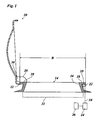
- Fig. 1 shows a fire damper 10 in the form of a dome light, which is held by a hinge 12 pivotally mounted on a curb 14, which is mounted on a roof, not shown, of a building.
- the curb 14 limits an opening 16, which serves as a smoke outlet opening in case of fire.
- a peripheral edge 18 of the opening 16 is formed by the upper surface of a flange 20 projecting horizontally outwardly from the top of the curb 14.
- the curb 14 for example, has the shape of a rectangular frame with a width B of, for example, 1.5 m and a length L (perpendicular to the plane in Fig. 1 ) of, for example, 2.8 m.
- a locking member 22 is disposed below the flange 20, with which the in Fig. 1 lock in the open position shown fire damper 10 in the closed position.
- the device for opening the fire damper 10 comprises a pressure source 24, for example a propellant or a compressed air network, and an actuator in the form of a bellows 26, which is expandable by the pressure medium generated by the pressure source 24.
- the bellows 26 extends on the hinge side of the top ring 14 at right angles to the plane in Fig. 1 approximately over the entire length of the respective leg of the cradle and is fixed with a part of its surface on a surface portion 28 of the flange 20 formed by the edge 18 of the opening 16, for example, glued.
- the fire damper 10 is held in the open position by the pressure of the pressure medium contained in the bellows 26.
- the bellows 26 is connected via a line 32 to the locking member 22, which in turn is connected via a line 34 to the pressure source 24.
- the pressure source 24 receives a signal from a smoke detector 36, which may be installed in the immediate vicinity of the opening 16 or optionally also at a central location in the building.
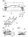
- Fig. 2 the fire damper 10 is shown in closed and locked to the locking member 22 position.
- the bellows 26 is folded in this state into a flat package and is located between the flange of the cap rim 14 and the corresponding edge region of the fire damper 10 to save space.
- the surface piece 28 of the flange 20 may also be slightly recessed, so that a flat chamber is formed for receiving the folded bellows. This has the advantage that the foil of the bellows 26 is better protected against the action of heat until the fire damper is opened.
- the smoke detector 36 When the smoke detector 36 reports smoke, it sends a signal to the pressure source 24 to initiate the supply of pressure to the pneumatic locking member 22, which then retracts a piston rod 38 and so lifts the lock of the fire damper. At the same time, the locking member 22 acts as a valve, which connects the lines 34 and 32 after unlocking, so that the pressure medium is introduced into the bellows 26 and this inflates. By doing this on the area 30 ( Fig. 1 ) the fire damper acting force is generated sufficient torque to open the fire damper.
- the width b of the package 26 folded bellows 26 and thus the width of the corresponding contact surfaces with the top ring 14 and the fire damper 10 is for example 5 cm.
- the required pressure P of the pressure medium can be calculated as follows:
- This pressure (4.5 bar) is therefore not greater than the pressure in a well-inflated bicycle tire.
- the hinge 12 is located directly on the edge of the bellows 26. If the hinge is moved a little farther away, as shown in the drawing, even smaller values are obtained for the required pressure.
- a possible design of the bellows 26 is shown.
- This bellows is formed by a thin, tear-resistant polymer film, which is folded into four layers 40, 42, 44, 46. Each of these layers has the width b and extends over the entire length L of the relevant leg of the top ring 14.
- the layers 40 and 42 are glued together at the ends by adhesive seams 48. Accordingly, the layers 44 and 46 are glued together by adhesive seams 50.
- adhesive seams 50 At the in Fig.
- the layers 40 and 46 are glued together at the free ends of the folded film by adhesive seams 52, 54, and the adhesive seams 54 at the end of the bladder connect to the adhesive seams 48 and 50, so that an all-sided closed bellows with two chambers is formed, which are formed between the layers 40 and 42 and 44 and 46 and communicate with each other.
- the bellows 26 can unfold like an accordion, wherein in the central region on most of the length of the bellows, the fold formed between the inner layers 42 and 44 can turn outward until the bellows finally the in Fig. 1 shown configuration.
- Fig. 4 the locking member 22 is shown in an axial section.
- This locking member forms a cylinder 56 in which a connected to the piston rod 38 piston 58 is guided.
- a spring 60 biases the piston into the locking position.
- the piston 58 When the piston 58 is pressurized via line 34, it moves counter to the force of the spring 60 to the left and pulls the piston rod 38 in the unlocked position back. Only when reaching the unlocked position, the piston releases the line 32, so that the pressure medium supplied via the line 34 can be forwarded via the line 32 to the bellows 26.
- the opening cross-section in the conduit 32 is slightly smaller than that of the conduit 34, so that in the cylinder 56 a certain overpressure is maintained, which holds the piston 58 in the unlocked position, as long as pressure medium is supplied via the line 34. Even if the spring 60 would push back the piston in the direction of the Verriegelungsstelldung, this would lead to a partial closing of the line 32 and thus to an increase in the pressure in the cylinder, and the piston would be pushed back to the unlocked position, until finally a Equilibrium sets.
- the locking member 22 can optionally also be used to regulate the flow rate of the pressure medium to the bellows 26.
- the piston rod on a ramp, so that the fire damper 10, when it is closed again, can automatically engage and thus the lock is restored.
- a connected to the piston rod 38 and led out of the cylinder 56 tension member 38 ' also allows manual unlocking regardless of a triggering case.
- locking members may be provided which are pneumatically connected in series.
- Fig. 5 shows a bellows 26 'according to a modified embodiment.
- a plate-shaped reinforcement 64 or 62 is attached to the outer layers 46 and 40 of the film, for example glued, which extends over the entire length of the bellows.
- the reinforcements can also be connected by a hinge and, in any case, are pivotable relative to one another during the expansion of the bellows.
- the reinforcements make the bladder a substantially rigid assembly which can be handled as a unit and thus more easily mounted on the curb leaves.
- the connection for the line 32 can then be stably integrated into the lower reinforcement 64.
- the hinge 12 may also be omitted in a modified embodiment. Its function is then taken over directly by the bellows 26 or the hinge connecting the reinforcements 62, 64.
- FIGS. 6 and 7 show an example of an opening device, which in addition to the emergency opening function offers the possibility to open the closure member controlled in two stages.
- the bellows on two separate chambers 26a, 26b which are each connected via a line 32a and 32b to the locking member 22.
- the conduit 32b includes a check valve 66 which opens toward the chamber 26b. If in case of fire the pressure source 24 ( FIG. 2 ) is activated, consequently both chambers 26a and 26b are acted upon by the locking member 22 and the check valve 66 with pressure medium, so that the closure member opens wide, optionally beyond an opening angle of 90 °, so that the closure member due to its own weight in the permanent open position overturns.
- the chambers 26 a and 26 b can also be connected via the lines 32 a, 32 b, additional control lines 68 a, 68 b and a valve 70 optionally with a compressed air line 72 or a vent line 74.
- the valve 70 has five positions a, b, c, d and e in the example shown.
- position a both control lines are locked, so that the closure member remains in the closed position as long as the emergency opening mechanism is not actuated.
- position b only the control line 68a is supplied with compressed air, while the control line 68b remains locked.
- the compressed air is prevented by the check valve 66 from flowing into the chamber 26a, so that only the chamber 26b with compressed air is filled. In this way, the closure member can be opened by a limited opening angle.
- a stop may be provided which limits the opening angle to less than 90 °.
- the stop can work similarly to the locking member 22, so that it is automatically withdrawn in an emergency in case of fire and then allows the overturning of the fire damper in the fully open position.
- the two chambers 26a and 26b are also used to adjust the closure member in a controlled manner in two different open positions, both corresponding to an opening angle of less than 90 °.
- This can be achieved, for example, in that the pressure in the compressed air line 72 is less than the outlet pressure of the pressure source 24 serving for the emergency release, so that the pressure in the compressed air line 72 is insufficient, even if both chambers 26a and 26b are acted upon Closing member to open more than 90 °.
- valve 70 is brought into the position c, in which both control lines 68a and 68b are supplied with compressed air.
- the check valve 66 is then bypassed so that both chambers of the bladder are expanded.
- valve 70 When the closure member is to be closed again, the valve 70 is brought to the position d, in which the control line 68 a is locked, while the control line 68 b is connected to the vent line 74. Consequently, in this position, only the chamber 2a6 is evacuated while the pressure in the chamber 26d is maintained.
- valve 70 When the closure member is to be completely closed again, the valve 70 is brought into the position e, in which both chambers are evacuated via the control lines 68a and 68d.
- the positions d and e are formed as temporary positions in which the valve can be held only by hand and from which it automatically returns to the position a. This ensures that the emergency release mechanism is always ready to work.
- a film hinge 76 which connects the two reinforcements 62, 64 together (or more generally: two hinge parts connects, which can also be formed directly through the fire damper 10 and the curb 14).
- the two chambers 26a and 26b of the bellows are formed by a single film web 78 whose longitudinal edges are turned inwards.
- the folded and struck back to the middle part of the film web parts form flaps 80 and are clamped at their edge in each case by a longitudinally extending of the hinge clamping plate 82 against the central part of the film web 78.
- the clamping plates 82 are secured to the respective reinforcement 62 and 64, respectively, with screws 84 distributed along the length.
- the bellows is securely fixed to the two reinforcements 62, 64, and at the same time the two chambers 26a, 26b are sealed at their longitudinal edges.
- Completion of the chambers 26a, 26b at both ends of the bladder may be accomplished in any conventional manner, for example by welding or, preferably, by flipping the ends of the film web (including the flaps) and then welding or gluing.
- the film hinge 76 is formed in the example shown by a single-layer strip of film web 78, which connects the two chambers 26a, 26b together.
- the width of this strip is dimensioned so that it corresponds exactly to the distance between the corresponding film layers of the chambers 26a, 26b caused by the clamping plates 82. In this way, the reinforcements 62, 64 in the closed Arrange position parallel to each other without the film hinge 76 is overstretched.
- the two chambers 26a, 26b of the bellows can also be formed by a closed film tube.
- the ends of the two flaps 80 would also be integrally connected to one another by a strip of material, so that the film hinge 76 would have two layers and a correspondingly higher stability.
- FIG. 8 and 9 show, as a further example, a device with which the fire damper 10 can be opened by introducing positive pressure into a bellows 26 "and closed again by introducing an underpressure, of which only one duct 86 serving to supply the negative pressure is shown connects the bellows 26 "with a venturi 88.
- a valve control analogous to the in Fig. 6 can be achieved that compressed air in the shown Fig. 8 indicated by an arrow direction out of the venturi, so that in the bellows 26 ", a negative pressure is generated.
- the bellows forms in this example only a single chamber and consists of a tube closed to a film layer, similar to Fig. 7 by clamping plates 82 on the two hinge parts, here the curb 18 and the fire damper 10, is attached.
- the two clamping plates 82 lie on both sides of the film hinge 76 formed by the film web.
- the two walls of the bellows 26 are here each fixed in a position remote from the film hinge 76 position by means of an additional clamping plate 90 to the cradle 18 and the frame of the fire damper 10. This makes it possible by generating a negative pressure in the interior of the bellows 26 "exert a tensile force on the fire damper 10 to move it in the closing direction.
- Fig. 9 shows the fire damper 10 in a pivoted up by 90 ° position in which it is held by the pressurized bellows 26 "If now the fire damper is to be closed, the compressed air supply is interrupted and instead via the venturi 28 a negative pressure in the bellows 26th "initiated. Then the bellows collapses, and tensile forces are exerted on the clamping plates 50, which generate a force acting in the closing direction on the fire damper 10.
- the above-described opening and closing mechanism is also functional when the fire damper 10 is opened in the open position by more than 90 °. However, then the closing torque generated by means of vacuum must be slightly larger.
- a manually or automatically, for example, pneumatically releasable locking mechanism may be provided, for example, a pneumatically operated mechanism that works similar to the locking member 22 according to Fig. 2 .
- the arrangement can also be chosen so that the lock in normal operation the Opening movement of the fire damper 10 limited so that the fire damper open by commands entered by the user by means of compressed air and close by means of negative pressure, but that in case of fire, the locking mechanism is automatically released, so that when the bellows 26 "expands, the fire damper 10 to 180 ° in the fully opened position and then remains in this position, so that a permanent unimpeded flue is guaranteed.
Landscapes
- Business, Economics & Management (AREA)
- Emergency Management (AREA)
- Engineering & Computer Science (AREA)
- Architecture (AREA)
- Civil Engineering (AREA)
- Structural Engineering (AREA)
- Air-Flow Control Members (AREA)
- Special Wing (AREA)
- Chain Conveyers (AREA)
- Automatic Analysis And Handling Materials Therefor (AREA)
- Diaphragms For Electromechanical Transducers (AREA)
- Power-Operated Mechanisms For Wings (AREA)
- Seal Device For Vehicle (AREA)
- Forklifts And Lifting Vehicles (AREA)
- Tents Or Canopies (AREA)
Applications Claiming Priority (2)
| Application Number | Priority Date | Filing Date | Title |
|---|---|---|---|
| DE202007000489U DE202007000489U1 (de) | 2007-01-12 | 2007-01-12 | Vorrichtung zum Betätigen schwenkbarer Verschlußglieder |
| EP08706978A EP2111493B1 (de) | 2007-01-12 | 2008-01-09 | Vorrichtung zum betätigen schwenkbarer verschlussglieder |
Related Parent Applications (1)
| Application Number | Title | Priority Date | Filing Date |
|---|---|---|---|
| EP08706978.7 Division | 2008-01-09 |
Publications (2)
| Publication Number | Publication Date |
|---|---|
| EP2204523A1 EP2204523A1 (de) | 2010-07-07 |
| EP2204523B1 true EP2204523B1 (de) | 2013-09-04 |
Family
ID=39333144
Family Applications (2)
| Application Number | Title | Priority Date | Filing Date |
|---|---|---|---|
| EP10155919.3A Not-in-force EP2204523B1 (de) | 2007-01-12 | 2008-01-09 | Rauchabzugsvorrichtung mit drehbarem Verschlusselement |
| EP08706978A Not-in-force EP2111493B1 (de) | 2007-01-12 | 2008-01-09 | Vorrichtung zum betätigen schwenkbarer verschlussglieder |
Family Applications After (1)
| Application Number | Title | Priority Date | Filing Date |
|---|---|---|---|
| EP08706978A Not-in-force EP2111493B1 (de) | 2007-01-12 | 2008-01-09 | Vorrichtung zum betätigen schwenkbarer verschlussglieder |
Country Status (5)
| Country | Link |
|---|---|
| EP (2) | EP2204523B1 (pl) |
| AT (1) | ATE502181T1 (pl) |
| DE (2) | DE202007000489U1 (pl) |
| PL (1) | PL2111493T3 (pl) |
| WO (1) | WO2008083963A1 (pl) |
Families Citing this family (3)
| Publication number | Priority date | Publication date | Assignee | Title |
|---|---|---|---|---|
| DE202011050327U1 (de) | 2011-06-01 | 2012-09-04 | Jörg Schwarzbich | Trägeranordnung für Solarmodule |
| DE102014106929B4 (de) * | 2014-05-16 | 2022-12-15 | Wegard Gmbh | Aktorelement |
| PL425422A1 (pl) * | 2018-05-02 | 2019-11-04 | Nowak Innovations Spolka Z Ograniczona Odpowiedzialnoscia | Sposoby awaryjnego otwierania otworów wejściowych w sytuacjach awaryjnych, urządzenia i systemy do ich realizacji oraz sposoby montażu urządzeń do awaryjnego otwierania ruchomych elementów montowanych w otworach wejściowych |
Family Cites Families (3)
| Publication number | Priority date | Publication date | Assignee | Title |
|---|---|---|---|---|
| US3202061A (en) * | 1962-07-09 | 1965-08-24 | Lowell B Johnston | Fluid actuated displacement and positioning system |
| GB1339021A (en) * | 1970-09-15 | 1973-11-28 | Dunlop Holdings Ltd | Rotary actuator |
| DE3134664A1 (de) * | 1981-09-02 | 1983-03-17 | Manfred Dr. 8011 Kirchheim Hingerle | "vorrichtung zum steuern eines fluegels von fenster, tueren oder dergleichen" |
-
2007
- 2007-01-12 DE DE202007000489U patent/DE202007000489U1/de not_active Expired - Lifetime
-
2008
- 2008-01-09 WO PCT/EP2008/000121 patent/WO2008083963A1/de not_active Ceased
- 2008-01-09 PL PL08706978T patent/PL2111493T3/pl unknown
- 2008-01-09 AT AT08706978T patent/ATE502181T1/de active
- 2008-01-09 DE DE502008002873T patent/DE502008002873D1/de active Active
- 2008-01-09 EP EP10155919.3A patent/EP2204523B1/de not_active Not-in-force
- 2008-01-09 EP EP08706978A patent/EP2111493B1/de not_active Not-in-force
Also Published As
| Publication number | Publication date |
|---|---|
| PL2111493T3 (pl) | 2011-08-31 |
| WO2008083963A1 (de) | 2008-07-17 |
| DE502008002873D1 (de) | 2011-04-28 |
| ATE502181T1 (de) | 2011-04-15 |
| EP2111493B1 (de) | 2011-03-16 |
| DE202007000489U1 (de) | 2008-05-15 |
| EP2204523A1 (de) | 2010-07-07 |
| EP2111493A1 (de) | 2009-10-28 |
Similar Documents
| Publication | Publication Date | Title |
|---|---|---|
| EP1137360B1 (de) | Filterbeutel für einen staubsauger | |
| DE2304019A1 (de) | Kopfsack | |
| EP2111493B1 (de) | Vorrichtung zum betätigen schwenkbarer verschlussglieder | |
| EP2094924A2 (de) | Türschloss für türen von luftfahrzeugen, insbesondere von hubschraubern | |
| EP3423314B1 (de) | Klappenscharnier für eine frontklappe eines fahrzeugs mit einem teleskopierbaren lenkerhebel | |
| DE4127201A1 (de) | Flexibler grossbehaelter mit auswechselbarer innenhuelle | |
| DE102013021803A1 (de) | Aufstieg zur Fahrzeugtür eines Kraftfahrzeugs | |
| DE102017001303A1 (de) | Verkleidungsanordnung zur Verkleidung eines Karosserieelements eines Fahrzeugs | |
| DE19919701A1 (de) | Rauchschutzeinrichtung für Gebäude | |
| DE3140043C2 (de) | Brandschutzklappe | |
| DE69932046T2 (de) | Ladungstützvorrichtung | |
| CH700311A1 (de) | Fahrzeugaufbau und Fahrzeug mit einem solchen umwandelbaren Aufbau. | |
| DE102011053197B4 (de) | Versorgungskanal mit aufblasbarem Projektionselement für ein Flugzeug, Verfahren zum Aus- und Einfahren des aufblasbaren Projektionselements und Verwendung eines Versorgungskanals in einem Flugzeug | |
| EP0499796A2 (de) | Sicherheitsverriegelung für ein Türblatt einer Schwing-oder Schwenktür | |
| DE10261860B4 (de) | Crashaktive Fronthaube an einem Fahrzueg | |
| EP1318045B1 (de) | Schwenkbare Sicherungsklappe für eine Ladebordwand | |
| DE102012013559B4 (de) | Vorrichtung zum Überbrücken und/oder Schließen eines Abstandes zwischen einer Laderampe und einer Ladefläche eines Fahrzeugs | |
| DE2717063C2 (de) | Dachluke an einem Fahrzeugdach | |
| AT511293B1 (de) | Sicherheitsaufprallvorrichtung für fahrzeuge | |
| CH374590A (de) | Ventil, insbesondere für Rohrpostanlagen | |
| DE102006038009B4 (de) | Vorrichtung zum Rauch- und Wärmeabzug von Räumen | |
| DE4141835A1 (de) | Schutzeinrichtung fuer insassen eines kraftfahrzeuges | |
| DE7621594U1 (de) | Luftdichte absperrklappe | |
| DE3011347A1 (de) | Zweifache trittstufen an einem kraftfahrzeug | |
| DE29614941U1 (de) | Brandschutzeinrichtung für eine Lüftungsrohrleitung |
Legal Events
| Date | Code | Title | Description |
|---|---|---|---|
| PUAI | Public reference made under article 153(3) epc to a published international application that has entered the european phase |
Free format text: ORIGINAL CODE: 0009012 |
|
| 17P | Request for examination filed |
Effective date: 20100309 |
|
| AC | Divisional application: reference to earlier application |
Ref document number: 2111493 Country of ref document: EP Kind code of ref document: P |
|
| AK | Designated contracting states |
Kind code of ref document: A1 Designated state(s): AT BE BG CH CY CZ DE DK EE ES FI FR GB GR HR HU IE IS IT LI LT LU LV MC MT NL NO PL PT RO SE SI SK TR |
|
| AX | Request for extension of the european patent |
Extension state: AL BA MK RS |
|
| GRAP | Despatch of communication of intention to grant a patent |
Free format text: ORIGINAL CODE: EPIDOSNIGR1 |
|
| RIC1 | Information provided on ipc code assigned before grant |
Ipc: E04D 13/035 20060101ALI20130122BHEP Ipc: E05F 1/10 20060101ALI20130122BHEP Ipc: E05F 15/04 20060101AFI20130122BHEP Ipc: E05F 1/00 20060101ALI20130122BHEP |
|
| GRAP | Despatch of communication of intention to grant a patent |
Free format text: ORIGINAL CODE: EPIDOSNIGR1 |
|
| GRAS | Grant fee paid |
Free format text: ORIGINAL CODE: EPIDOSNIGR3 |
|
| GRAA | (expected) grant |
Free format text: ORIGINAL CODE: 0009210 |
|
| INTG | Intention to grant announced |
Effective date: 20130723 |
|
| AC | Divisional application: reference to earlier application |
Ref document number: 2111493 Country of ref document: EP Kind code of ref document: P |
|
| AK | Designated contracting states |
Kind code of ref document: B1 Designated state(s): AT BE BG CH CY CZ DE DK EE ES FI FR GB GR HR HU IE IS IT LI LT LU LV MC MT NL NO PL PT RO SE SI SK TR |
|
| REG | Reference to a national code |
Ref country code: GB Ref legal event code: FG4D Free format text: NOT ENGLISH |
|
| REG | Reference to a national code |
Ref country code: CH Ref legal event code: EP |
|
| REG | Reference to a national code |
Ref country code: AT Ref legal event code: REF Ref document number: 630652 Country of ref document: AT Kind code of ref document: T Effective date: 20130915 |
|
| REG | Reference to a national code |
Ref country code: IE Ref legal event code: FG4D Free format text: LANGUAGE OF EP DOCUMENT: GERMAN |
|
| REG | Reference to a national code |
Ref country code: NL Ref legal event code: T3 |
|
| REG | Reference to a national code |
Ref country code: DE Ref legal event code: R096 Ref document number: 502008010619 Country of ref document: DE Effective date: 20131031 |
|
| PG25 | Lapsed in a contracting state [announced via postgrant information from national office to epo] |
Ref country code: SE Free format text: LAPSE BECAUSE OF FAILURE TO SUBMIT A TRANSLATION OF THE DESCRIPTION OR TO PAY THE FEE WITHIN THE PRESCRIBED TIME-LIMIT Effective date: 20130904 Ref country code: HR Free format text: LAPSE BECAUSE OF FAILURE TO SUBMIT A TRANSLATION OF THE DESCRIPTION OR TO PAY THE FEE WITHIN THE PRESCRIBED TIME-LIMIT Effective date: 20130904 Ref country code: NO Free format text: LAPSE BECAUSE OF FAILURE TO SUBMIT A TRANSLATION OF THE DESCRIPTION OR TO PAY THE FEE WITHIN THE PRESCRIBED TIME-LIMIT Effective date: 20131204 Ref country code: LT Free format text: LAPSE BECAUSE OF FAILURE TO SUBMIT A TRANSLATION OF THE DESCRIPTION OR TO PAY THE FEE WITHIN THE PRESCRIBED TIME-LIMIT Effective date: 20130904 Ref country code: CY Free format text: LAPSE BECAUSE OF FAILURE TO SUBMIT A TRANSLATION OF THE DESCRIPTION OR TO PAY THE FEE WITHIN THE PRESCRIBED TIME-LIMIT Effective date: 20130828 |
|
| REG | Reference to a national code |
Ref country code: LT Ref legal event code: MG4D |
|
| PG25 | Lapsed in a contracting state [announced via postgrant information from national office to epo] |
Ref country code: LV Free format text: LAPSE BECAUSE OF FAILURE TO SUBMIT A TRANSLATION OF THE DESCRIPTION OR TO PAY THE FEE WITHIN THE PRESCRIBED TIME-LIMIT Effective date: 20130904 Ref country code: PL Free format text: LAPSE BECAUSE OF FAILURE TO SUBMIT A TRANSLATION OF THE DESCRIPTION OR TO PAY THE FEE WITHIN THE PRESCRIBED TIME-LIMIT Effective date: 20130904 Ref country code: FI Free format text: LAPSE BECAUSE OF FAILURE TO SUBMIT A TRANSLATION OF THE DESCRIPTION OR TO PAY THE FEE WITHIN THE PRESCRIBED TIME-LIMIT Effective date: 20130904 Ref country code: GR Free format text: LAPSE BECAUSE OF FAILURE TO SUBMIT A TRANSLATION OF THE DESCRIPTION OR TO PAY THE FEE WITHIN THE PRESCRIBED TIME-LIMIT Effective date: 20131205 Ref country code: SI Free format text: LAPSE BECAUSE OF FAILURE TO SUBMIT A TRANSLATION OF THE DESCRIPTION OR TO PAY THE FEE WITHIN THE PRESCRIBED TIME-LIMIT Effective date: 20130904 |
|
| PG25 | Lapsed in a contracting state [announced via postgrant information from national office to epo] |
Ref country code: CY Free format text: LAPSE BECAUSE OF FAILURE TO SUBMIT A TRANSLATION OF THE DESCRIPTION OR TO PAY THE FEE WITHIN THE PRESCRIBED TIME-LIMIT Effective date: 20130904 |
|
| PG25 | Lapsed in a contracting state [announced via postgrant information from national office to epo] |
Ref country code: EE Free format text: LAPSE BECAUSE OF FAILURE TO SUBMIT A TRANSLATION OF THE DESCRIPTION OR TO PAY THE FEE WITHIN THE PRESCRIBED TIME-LIMIT Effective date: 20130904 Ref country code: IS Free format text: LAPSE BECAUSE OF FAILURE TO SUBMIT A TRANSLATION OF THE DESCRIPTION OR TO PAY THE FEE WITHIN THE PRESCRIBED TIME-LIMIT Effective date: 20140104 Ref country code: CZ Free format text: LAPSE BECAUSE OF FAILURE TO SUBMIT A TRANSLATION OF THE DESCRIPTION OR TO PAY THE FEE WITHIN THE PRESCRIBED TIME-LIMIT Effective date: 20130904 Ref country code: SK Free format text: LAPSE BECAUSE OF FAILURE TO SUBMIT A TRANSLATION OF THE DESCRIPTION OR TO PAY THE FEE WITHIN THE PRESCRIBED TIME-LIMIT Effective date: 20130904 Ref country code: RO Free format text: LAPSE BECAUSE OF FAILURE TO SUBMIT A TRANSLATION OF THE DESCRIPTION OR TO PAY THE FEE WITHIN THE PRESCRIBED TIME-LIMIT Effective date: 20130904 |
|
| PG25 | Lapsed in a contracting state [announced via postgrant information from national office to epo] |
Ref country code: ES Free format text: LAPSE BECAUSE OF FAILURE TO SUBMIT A TRANSLATION OF THE DESCRIPTION OR TO PAY THE FEE WITHIN THE PRESCRIBED TIME-LIMIT Effective date: 20130904 |
|
| REG | Reference to a national code |
Ref country code: DE Ref legal event code: R097 Ref document number: 502008010619 Country of ref document: DE |
|
| PG25 | Lapsed in a contracting state [announced via postgrant information from national office to epo] |
Ref country code: PT Free format text: LAPSE BECAUSE OF FAILURE TO SUBMIT A TRANSLATION OF THE DESCRIPTION OR TO PAY THE FEE WITHIN THE PRESCRIBED TIME-LIMIT Effective date: 20140106 |
|
| PLBE | No opposition filed within time limit |
Free format text: ORIGINAL CODE: 0009261 |
|
| STAA | Information on the status of an ep patent application or granted ep patent |
Free format text: STATUS: NO OPPOSITION FILED WITHIN TIME LIMIT |
|
| BERE | Be: lapsed |
Owner name: SCHWARZBICH, JORG Effective date: 20140131 |
|
| 26N | No opposition filed |
Effective date: 20140605 |
|
| PG25 | Lapsed in a contracting state [announced via postgrant information from national office to epo] |
Ref country code: LU Free format text: LAPSE BECAUSE OF FAILURE TO SUBMIT A TRANSLATION OF THE DESCRIPTION OR TO PAY THE FEE WITHIN THE PRESCRIBED TIME-LIMIT Effective date: 20140109 Ref country code: MC Free format text: LAPSE BECAUSE OF FAILURE TO SUBMIT A TRANSLATION OF THE DESCRIPTION OR TO PAY THE FEE WITHIN THE PRESCRIBED TIME-LIMIT Effective date: 20130904 Ref country code: IT Free format text: LAPSE BECAUSE OF FAILURE TO SUBMIT A TRANSLATION OF THE DESCRIPTION OR TO PAY THE FEE WITHIN THE PRESCRIBED TIME-LIMIT Effective date: 20130904 |
|
| REG | Reference to a national code |
Ref country code: CH Ref legal event code: PL |
|
| REG | Reference to a national code |
Ref country code: DE Ref legal event code: R097 Ref document number: 502008010619 Country of ref document: DE Effective date: 20140605 |
|
| PG25 | Lapsed in a contracting state [announced via postgrant information from national office to epo] |
Ref country code: DK Free format text: LAPSE BECAUSE OF FAILURE TO SUBMIT A TRANSLATION OF THE DESCRIPTION OR TO PAY THE FEE WITHIN THE PRESCRIBED TIME-LIMIT Effective date: 20130904 |
|
| PG25 | Lapsed in a contracting state [announced via postgrant information from national office to epo] |
Ref country code: LI Free format text: LAPSE BECAUSE OF NON-PAYMENT OF DUE FEES Effective date: 20140131 Ref country code: CH Free format text: LAPSE BECAUSE OF NON-PAYMENT OF DUE FEES Effective date: 20140131 |
|
| REG | Reference to a national code |
Ref country code: FR Ref legal event code: ST Effective date: 20140930 |
|
| REG | Reference to a national code |
Ref country code: IE Ref legal event code: MM4A |
|
| PG25 | Lapsed in a contracting state [announced via postgrant information from national office to epo] |
Ref country code: FR Free format text: LAPSE BECAUSE OF NON-PAYMENT OF DUE FEES Effective date: 20140131 |
|
| PG25 | Lapsed in a contracting state [announced via postgrant information from national office to epo] |
Ref country code: BE Free format text: LAPSE BECAUSE OF NON-PAYMENT OF DUE FEES Effective date: 20140131 Ref country code: IE Free format text: LAPSE BECAUSE OF NON-PAYMENT OF DUE FEES Effective date: 20140109 |
|
| REG | Reference to a national code |
Ref country code: AT Ref legal event code: MM01 Ref document number: 630652 Country of ref document: AT Kind code of ref document: T Effective date: 20140109 |
|
| PG25 | Lapsed in a contracting state [announced via postgrant information from national office to epo] |
Ref country code: AT Free format text: LAPSE BECAUSE OF NON-PAYMENT OF DUE FEES Effective date: 20140109 |
|
| PG25 | Lapsed in a contracting state [announced via postgrant information from national office to epo] |
Ref country code: MT Free format text: LAPSE BECAUSE OF FAILURE TO SUBMIT A TRANSLATION OF THE DESCRIPTION OR TO PAY THE FEE WITHIN THE PRESCRIBED TIME-LIMIT Effective date: 20130904 |
|
| PG25 | Lapsed in a contracting state [announced via postgrant information from national office to epo] |
Ref country code: BG Free format text: LAPSE BECAUSE OF FAILURE TO SUBMIT A TRANSLATION OF THE DESCRIPTION OR TO PAY THE FEE WITHIN THE PRESCRIBED TIME-LIMIT Effective date: 20130904 |
|
| PG25 | Lapsed in a contracting state [announced via postgrant information from national office to epo] |
Ref country code: HU Free format text: LAPSE BECAUSE OF FAILURE TO SUBMIT A TRANSLATION OF THE DESCRIPTION OR TO PAY THE FEE WITHIN THE PRESCRIBED TIME-LIMIT; INVALID AB INITIO Effective date: 20080109 Ref country code: TR Free format text: LAPSE BECAUSE OF FAILURE TO SUBMIT A TRANSLATION OF THE DESCRIPTION OR TO PAY THE FEE WITHIN THE PRESCRIBED TIME-LIMIT Effective date: 20130904 |
|
| PGFP | Annual fee paid to national office [announced via postgrant information from national office to epo] |
Ref country code: DE Payment date: 20190131 Year of fee payment: 12 Ref country code: GB Payment date: 20190124 Year of fee payment: 12 Ref country code: NL Payment date: 20190122 Year of fee payment: 12 |
|
| REG | Reference to a national code |
Ref country code: DE Ref legal event code: R119 Ref document number: 502008010619 Country of ref document: DE |
|
| REG | Reference to a national code |
Ref country code: NL Ref legal event code: MM Effective date: 20200201 |
|
| GBPC | Gb: european patent ceased through non-payment of renewal fee |
Effective date: 20200109 |
|
| PG25 | Lapsed in a contracting state [announced via postgrant information from national office to epo] |
Ref country code: NL Free format text: LAPSE BECAUSE OF NON-PAYMENT OF DUE FEES Effective date: 20200201 Ref country code: DE Free format text: LAPSE BECAUSE OF NON-PAYMENT OF DUE FEES Effective date: 20200801 Ref country code: GB Free format text: LAPSE BECAUSE OF NON-PAYMENT OF DUE FEES Effective date: 20200109 |