EP2204547A1 - Gleichrichterstufeanordnung eines Turbotriebwerks, die einen Außenring und mindestens eine Leitschaufel umfasst - Google Patents
Gleichrichterstufeanordnung eines Turbotriebwerks, die einen Außenring und mindestens eine Leitschaufel umfasst Download PDFInfo
- Publication number
- EP2204547A1 EP2204547A1 EP08173011A EP08173011A EP2204547A1 EP 2204547 A1 EP2204547 A1 EP 2204547A1 EP 08173011 A EP08173011 A EP 08173011A EP 08173011 A EP08173011 A EP 08173011A EP 2204547 A1 EP2204547 A1 EP 2204547A1
- Authority
- EP
- European Patent Office
- Prior art keywords
- platform
- contour
- opening
- blade
- shell
- Prior art date
- Legal status (The legal status is an assumption and is not a legal conclusion. Google has not performed a legal analysis and makes no representation as to the accuracy of the status listed.)
- Granted
Links
Images


Classifications
-
- F—MECHANICAL ENGINEERING; LIGHTING; HEATING; WEAPONS; BLASTING
- F01—MACHINES OR ENGINES IN GENERAL; ENGINE PLANTS IN GENERAL; STEAM ENGINES
- F01D—NON-POSITIVE DISPLACEMENT MACHINES OR ENGINES, e.g. STEAM TURBINES
- F01D9/00—Stators
- F01D9/02—Nozzles; Nozzle boxes; Stator blades; Guide conduits, e.g. individual nozzles
- F01D9/04—Nozzles; Nozzle boxes; Stator blades; Guide conduits, e.g. individual nozzles forming ring or sector
- F01D9/042—Nozzles; Nozzle boxes; Stator blades; Guide conduits, e.g. individual nozzles forming ring or sector fixing blades to stators
- F01D9/044—Nozzles; Nozzle boxes; Stator blades; Guide conduits, e.g. individual nozzles forming ring or sector fixing blades to stators permanently, e.g. by welding, brazing, casting or the like
-
- F—MECHANICAL ENGINEERING; LIGHTING; HEATING; WEAPONS; BLASTING
- F05—INDEXING SCHEMES RELATING TO ENGINES OR PUMPS IN VARIOUS SUBCLASSES OF CLASSES F01-F04
- F05D—INDEXING SCHEME FOR ASPECTS RELATING TO NON-POSITIVE-DISPLACEMENT MACHINES OR ENGINES, GAS-TURBINES OR JET-PROPULSION PLANTS
- F05D2230/00—Manufacture
- F05D2230/20—Manufacture essentially without removing material
- F05D2230/23—Manufacture essentially without removing material by permanently joining parts together
- F05D2230/232—Manufacture essentially without removing material by permanently joining parts together by welding
Definitions
- the invention relates to a fixed blade and the outer shell of a rectifier stage (or stator stage) of a turbomachine such as a turbojet or turboprop, the shell forming a housing supporting series of vanes fixed between which are arranged series of blades rotating in rotation about a longitudinal axis, in particular for an axial compressor or a turbine used in an aviation turbojet engine.
- the axis of the turbomachine is the axis of rotation of the rotor of the turbomachine.
- the axial direction corresponds to the direction of the axis of the turbomachine and a radial direction is a direction perpendicular to this axis.
- an axial plane is a plane containing the axis of the turbomachine, a transverse plane is a plane perpendicular to this axis and a radial plane is a plane perpendicular to the other two.
- the adjectives "inside” and “outside” are used with reference to a radial direction so that the portion or the (radially) inner face of an element is closer to the axis of the turbomachine than the part or the outer (radially) face of the same element.
- the present invention also relates to an assembly for a rectifying stage of an axial compressor, comprising an outer shell and at least one fixed blade, an axial compressor operating at low or high pressure comprising such an assembly and the turbomachine comprising such an axial compressor, a turbine comprising such an assembly and the turbomachine comprising such a turbine.
- the invention also relates to a rectifier stage for an axial compressor comprising at least one assembly as presented above, an axial compressor comprising such a rectifier stage and a turbomachine comprising such an axial compressor, a turbine comprising such a rectifier stage. and the turbine engine comprising such a turbine.
- the present invention relates to the method of mounting by welding between an outer shell and the top of at least one fixed blade.
- This outer shell forms a portion of the radially outer limit of the aerodynamic vein along which the air circulates in one of the rectifier stages of the compressor or the turbine of a turbomachine.
- this connection between the vanes and the outer ring is formed by fastening elements with threaded parts, such as threaded rods and bolts, as described in the document EP 1801357 .
- the document US 5474419 in particular plans to weld the tops of the blades fixed in openings through the outer shell and having a complementary shape with the top of the blades.
- the present invention aims to provide a solution to overcome the disadvantages of the prior art and in particular offering the possibility of not meeting the aforementioned problems inherent in threaded fastening techniques or the implementation of a welding throughout the thickness of the outer shell.
- a blade intended to form a fixed blade of a rectifying stage of a turbomachine, comprising a foot and a summit between which the body of the dawn extends. (or blade) which is connected to the top by a recess portion, the blade being characterized in that the top comprises a non-pierced platform constituting the terminal end portion, and whose contour surrounds the embedding portion dawn, and in that the outline of the platform has the shape of a regular polygon, in particular a quadrilateral, including a rectangle, or the shape of a bean.
- an outer shell for the rectifier stage of a turbomachine comprising a series of transversely aligned openings adapted to receive the top of fixed vanes comprising a platform which is adapted to penetrate into one of said openings, to allow the mounting of each fixed blade by welding between the edge of an opening and the contour of the platform, each opening having an inner portion opening on the inner face of the ferrule and an outer portion (forming a recess) opening on the outer face of the ferrule, the contour of the outer portion radially projecting, with a certain distance, the contour of the inner portion; delimiting a bearing surface facing the outer portion, the ferrule not comprising other drilling for mounting the blades.
- the first contour of a first part / part surrounds the second contour of a second part / part, this means, unless otherwise stated, that the second contour is inscribed in the first contour with a gap separating the first contour of the second contour, which contours are thus at a distance from one another.
- the platform is simple and consists of an outer portion.
- the portion recess is formed of a portion of the body of the blade (outer section) and the connection area between the body of the blade and the platform.
- the platform is dual.
- the platform comprises an outer portion forming the end of the top and, in addition, an inner portion forming part of the embedding portion and connecting the outer portion to the remainder of the blade, the outline of the outer portion surrounding, in radial projection, the outline of the inner portion.
- the blade is permanently mounted on the outer shell by forming a welded connection between the contour of the outer portion of an opening and the contour of the outer portion of the platform.
- This solution also has the additional advantage of allowing, in addition, not having to use a specific piece called "beam stop” which usually has the role of preventing the welding beam from thermally affecting the rest of the body. 'dawn. Indeed, according to the invention, it is the inner wall zone of the outer shell which is located between two openings which plays this role.
- the offset, in radial projection, between the contour of the outer portion of an opening of the outer shell and the contour of the inner portion of the same opening defines a heel at the inner wall zone of the outer shell, which has the bearing surface directed towards the outer portion of the opening and against which an inner face of the platform is supported.
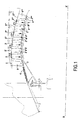
- the rectifier stage 2 comprises an outer shell 5 and an inner shell 4 concentric about the axis of symmetry and rotation X-X ', between which is mounted a series of blades 6.
- the blade 6 is connected by its foot to the inner shell 4 and its top 62 to the outer shell 5, the body 61 of the blade extending between the foot and the summit 62.
- the body 61 of the blade is extended by a platform 621 via a connection zone 623 in the form of a connecting radius.
- the average planes of the platform 621 and the body 61 are orthogonal to each other.
- the outline of the platform 621 has the form of a quadrilateral, more precisely of a parallelogram, and in particular of a rectangle whose length is oriented parallel to the width of the body 61 of the blade and whose width is oriented perpendicularly to the axial direction XX 'of the shell 5 (or the turbomachine).
- the outline of the platform 621 is in the form of a bean, i.e. a generally curved shape with an almost constant width over most of the longitudinal extent of the platform 621.
- This platform 621 constitutes an outer portion 621a forming the end of the top 62 of the blade 6, and has a substantially flat outer face which preferably takes up the radius of curvature of the outer face of the outer shell 5.
- Such a platform 621 is carried out by conventional techniques of forging a blank of the entire blade 6 and subsequent grinding by machining.
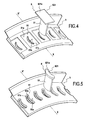
- the outer shell 5 has openings 51 aligned transversely, each of the openings 51 passing through the wall of the outer shell from one side to the other to receive the top 62 of a blade 6 fixed as previously presented.
- the openings 51 are generally elongate in a direction close to that of the axis X-X '.
- each opening 51 has an outer section 51a opening on the outer face of the outer shell 5 and an inner section 51b opening on the inner face of the outer shell 5 (downwards on the outer shell 5).
- figures 2 , 4 and 5 are figures 2 , 4 and 5 ).
- the outer portion 51a and the inner portion 51b are connected by a bearing face 51c facing the outer portion 51a of the opening 51.
- the outer portion 51a of the opening 51 forms a recess housing the platform 621 consisting of the outer portion 621a.
- the inner portion 51b of the opening 51 delimits a passage housing the corresponding embedding portion of the blade which is formed, in the case of this first embodiment, of the connection zone 623 and the outer portion 611 of the body 61 of dawn 6.
- the outline of the outer portion 51a has the shape of a regular polygon, in particular a quadrilateral , including a rectangle ( figure 4 ), or the shape of a bean ( figure 5 ).
- these contours are of identical shape with relatively close dimensions, the outline of the outer portion 51a of the opening 51 being slightly wider than the contour of the platform 621 to accommodate the latter.
- the outer wall area 53 of the shell 5 extends between the outer sections 51a of the openings 51.
- the contour of the inner section 51b has a shape similar to that of the contour of the section, in a radial plane, of the body 61 of the blade, namely a bean form.
- the thickness in the radial direction of the platform 621 substantially corresponds to the depth of the recess formed by the outer portion 51a of the opening 51.
- the thickness of the platform 621 it is possible for the thickness of the platform 621 to have a thickness smaller or greater than the depth of the outer section 51a of the opening 51, provided that a greater part of the thickness of the platform 621 is accommodated in the outer portion 51a of the opening 51, and this to allow the realization of a welded connection sufficiently strong mechanically.
- the platform 621 of the blades 6 is double or staged.
- the platform 621 comprises an outer portion 621a, forming the end of the top 62 of the blade 6, and an inner portion 621b connecting the outer portion 621a to the remainder of the blade 6, the contour of the outer portion 621a surrounding, in radial projection, the outline of the inner portion 621b.
- the outer portion 621a of the platform 621 is housed in the outer section 51a of an opening 51 of the shell and the inner portion 621b of the platform 621 is housed in the inner section 51b of the same opening 51 so that the inner face 621c of the outer portion 621a of the platform 621 bears against the bearing face 51c of the opening 51 of the ferrule 5.
- connection zone 623 connects the body of the blade 6 to the inner portion 621b of the platform 621.
- the inner portion 51b of the opening 51 defines a passage housing the corresponding embedding portion of the blade which is formed, in the case of this second embodiment, the inner portion 621b of the platform 621.
- the inner portion 621b of the platform 621 is only housed, without special connection, in the inner portion 51b of the opening 51, with a support between the inner face 621c of the outer portion 621a and the bearing face 51c of the inner wall zone 52 of the ferrule.
- the outline of the inner portion 51b of the opening 51 has the shape of a regular polygon, in particular a quadrilateral, in particular a rectangle (see figure 6 ), or the shape of a bean (case not shown).
- the outer and inner portions 51a and 51b of the opening 51 and the outer and inner portions 621a 621b of the platform 621 are in the form of a rectangle, but this second embodiment, in which the platform is double, also applies. if other forms are used, including another form of regular polygon, in particular a quadrilateral, or a form of bean.
- the thickness, in the radial direction, of the outer portion 621a of the platform 621 is a little larger than the depth of the recess formed by the outer portion 51a of the opening 51.
- the thickness of the outer portion 621a of the platform 621 is substantially equal to or slightly smaller than the depth of the outer section 51a of the opening 51, provided that a major part of the thickness of the outer portion 621a of the platform 621 is housed in the outer portion 51a of the opening 51, and this to allow the realization of a welded connection sufficiently mechanically resistant.
- the inner portion 621b of the platform 621 has a thickness, in radial direction, which is substantially equal to the thickness of the inner portion 51b of the opening 51.
- the internal ferrule face 5 and the inner face of the inner portion 621b of the platform 621 are in the circumferential extension of one another.
- FIG 8 presenting an alternative embodiment of the figure 6 for which the contours of the outer sections 51a and 51b inner opening 51 and the outlines of the outer portions 621a and 621b interior of the platform 621 have rounded corners.
- the outer and inner portions 51a and 51b of the opening 51 and the outer and inner portions 621a 621b of the platform 621 are in the form of a rectangle, but this variant also applies if other shapes are used, in particular another regular polygon shape, especially a quadrilateral, or a form of bean.
- the thickness of the outer portion 621a of the platform 621 has a thickness a little larger than the depth of the outer portion 51a of the opening 51.
- the outer portions 51a of the openings 51 define, on the outer face, an annular housing.
- the bearing faces 51c of two adjacent openings 51 are in the extension of one another and there is no longer an outer wall zone 53 between two openings 51.
- This variant allows the implantation of a maximum number of blades 6 in each rectifier stage while ensuring a high strength of the connection between the ferrule 5 and each fixed blade 6.
- the weld line extends along the edges of the outer portion 621a of the platforms 621 of two adjacent blades 6.
- the outer portion 621a of the platform 62 (which constitutes the entire platform in the first embodiment) has a thickness smaller than that of the opening 51 of the outer shell 5: this is the recessed portion located just in below the outer portion 621a of the platform 62 (connection zone 623 and outer portion 611 of the body 61 of the blade 6 for the first embodiment and inner portion 621b of the platform 621 for the second embodiment) which fills the inner section 51b of the platform 51.
- This is possible because the contour of the outer section 51a of the platform 51 surrounds the contour of the inner section 51b of the platform 51. In this way, the underside of the outer portion 621a of the platform 62 comes against the bearing face 51c.
- Welding can be achieved by any available welding technique, including electron beam welding, welding laser (such as high power CO2) or TIG arc welding.
- the shell 5 does not include any other hole than the openings 51 for mounting the blades 6, since, according to the invention, a welded connection is used between the outer shell 5 and the blades 6, and not a bolted or riveted connection.
- the weld bead is formed on the outer face of the shell by connecting the edge of the outer portion of the opening 51 to the contour of the platform 621.
- At least a major part of the thickness of the platform 621 housed in the outer portion 51a of an opening 51 of the ferrule 5 and / or the thickness of the platform 621 is equal to or greater than the thickness of the outer section 51a of an opening 51 of the ferrule 5.
- the contour of the platform 621 surrounds the contour of the body 61 of the blade 6. In this way, as the radial projection of the outer portion 621a of the platform is removed from the body 61 of the blade 6, this body 61 is not in the direction of the welding beam and then the weld line that is created.
- this arrangement makes it possible, because the weld bead is, in a radial projection, outside the contour of the blade 6, to be able to perform non-destructive checks of the X-ray weld seam whose image is not hindered by the presence of dawn 6.
- the weld bead has a certain length, which makes it possible to distribute the forces to which it is subjected on a larger surface whereas it is a zone weakened by the weld which generates a degradation of the properties mechanical.
Landscapes
- Engineering & Computer Science (AREA)
- Mechanical Engineering (AREA)
- General Engineering & Computer Science (AREA)
- Structures Of Non-Positive Displacement Pumps (AREA)
Priority Applications (3)
| Application Number | Priority Date | Filing Date | Title |
|---|---|---|---|
| EP08173011.1A EP2204547B1 (de) | 2008-12-29 | 2008-12-29 | Außenring und Verfahren zum Schweissen einer Leitschaufel auf diesem Außenring |
| CA2688882A CA2688882C (fr) | 2008-12-29 | 2009-12-22 | Ensemble pour etage redresseur d'une turbomachine, comprenant une virole exterieure et au moins une aube fixe |
| US12/648,836 US8430629B2 (en) | 2008-12-29 | 2009-12-29 | Assembly for a stator stage of a turbomachine, the assembly comprising an outer shroud and at least one stationary vane |
Applications Claiming Priority (1)
| Application Number | Priority Date | Filing Date | Title |
|---|---|---|---|
| EP08173011.1A EP2204547B1 (de) | 2008-12-29 | 2008-12-29 | Außenring und Verfahren zum Schweissen einer Leitschaufel auf diesem Außenring |
Publications (2)
| Publication Number | Publication Date |
|---|---|
| EP2204547A1 true EP2204547A1 (de) | 2010-07-07 |
| EP2204547B1 EP2204547B1 (de) | 2013-12-11 |
Family
ID=40613058
Family Applications (1)
| Application Number | Title | Priority Date | Filing Date |
|---|---|---|---|
| EP08173011.1A Active EP2204547B1 (de) | 2008-12-29 | 2008-12-29 | Außenring und Verfahren zum Schweissen einer Leitschaufel auf diesem Außenring |
Country Status (3)
| Country | Link |
|---|---|
| US (1) | US8430629B2 (de) |
| EP (1) | EP2204547B1 (de) |
| CA (1) | CA2688882C (de) |
Cited By (9)
| Publication number | Priority date | Publication date | Assignee | Title |
|---|---|---|---|---|
| EP2371521A1 (de) * | 2010-04-02 | 2011-10-05 | Techspace Aero S.A. | Verfahren zur Herstellung eines Gleichrichters |
| FR2970733A1 (fr) * | 2011-01-25 | 2012-07-27 | Snecma | Procede de controle du calage de pales dans un redresseur de turboreacteur, et pale de redresseur. |
| US20140314548A1 (en) * | 2011-12-30 | 2014-10-23 | Rolls-Royce Corporation | Turbine engine and vane system |
| WO2016142631A1 (fr) * | 2015-03-11 | 2016-09-15 | Microturbo | Réalisation de demi-etages de redresseurs monoblocs, par fabrication additive |
| EP3159485A1 (de) * | 2015-10-20 | 2017-04-26 | General Electric Company | Generativ gefertigte verbindung für eine turbinendüse |
| US9884393B2 (en) | 2015-10-20 | 2018-02-06 | General Electric Company | Repair methods utilizing additively manufacturing for rotor blades and components |
| US9914172B2 (en) | 2015-10-20 | 2018-03-13 | General Electric Company | Interlocking material transition zone with integrated film cooling |
| US10180072B2 (en) | 2015-10-20 | 2019-01-15 | General Electric Company | Additively manufactured bladed disk |
| US10370975B2 (en) | 2015-10-20 | 2019-08-06 | General Electric Company | Additively manufactured rotor blades and components |
Families Citing this family (14)
| Publication number | Priority date | Publication date | Assignee | Title |
|---|---|---|---|---|
| US9840917B2 (en) * | 2011-12-13 | 2017-12-12 | United Technologies Corporation | Stator vane shroud having an offset |
| EP2692995B1 (de) * | 2012-07-30 | 2017-09-20 | Ansaldo Energia IP UK Limited | Stationäre Gasturbinenmotor und Verfahren zur Durchführung von Instandhaltungsarbeit |
| FR2995344B1 (fr) * | 2012-09-10 | 2014-09-26 | Snecma | Procede de fabrication d'un carter d'echappement en materiau composite pour moteur a turbine a gaz et carter d'echappement ainsi obtenu |
| EP2738356B1 (de) * | 2012-11-29 | 2019-05-01 | Safran Aero Boosters SA | Statorschaufel einer Strömungsmaschine, Statorschaufelkranz einer Strömungsmaschine und zugehöriges Montageverfahren |
| CA2903738A1 (en) * | 2013-03-07 | 2014-09-12 | Rolls-Royce Canada, Ltd. | Gas turbine engine comprising an outboard insertion system of vanes and corresponding assembling method |
| US9844826B2 (en) | 2014-07-25 | 2017-12-19 | Honeywell International Inc. | Methods for manufacturing a turbine nozzle with single crystal alloy nozzle segments |
| US10697314B2 (en) | 2016-10-14 | 2020-06-30 | Rolls-Royce Corporation | Turbine shroud with I-beam construction |
| DE102017215874A1 (de) * | 2017-09-08 | 2019-03-14 | Man Diesel & Turbo Se | Leitschaufel, Leitvorrichtung und Strömungsmaschine |
| US10557365B2 (en) | 2017-10-05 | 2020-02-11 | Rolls-Royce Corporation | Ceramic matrix composite blade track with mounting system having reaction load distribution features |
| GB201720314D0 (en) * | 2017-12-06 | 2018-01-17 | Rolls Royce Plc | Aerofil joint recess |
| US11149563B2 (en) | 2019-10-04 | 2021-10-19 | Rolls-Royce Corporation | Ceramic matrix composite blade track with mounting system having axial reaction load distribution features |
| US11268394B2 (en) * | 2020-03-13 | 2022-03-08 | General Electric Company | Nozzle assembly with alternating inserted vanes for a turbine engine |
| US11629606B2 (en) * | 2021-05-26 | 2023-04-18 | General Electric Company | Split-line stator vane assembly |
| USD1010905S1 (en) | 2021-08-11 | 2024-01-09 | RAB Lighting Inc. | Adjustable high bay light fixture |
Citations (7)
| Publication number | Priority date | Publication date | Assignee | Title |
|---|---|---|---|---|
| GB599231A (en) | 1945-10-23 | 1948-03-08 | Guillermo Enrique Carlos Kraft | Improvements in rotary files for card indexes |
| GB599391A (en) * | 1945-05-25 | 1948-03-11 | Power Jets Res & Dev Ltd | Improvements in and relating to axial flow compressors, turbines and the like machines |
| US2834537A (en) | 1954-01-18 | 1958-05-13 | Ryan Aeronautical Co | Compressor stator structure |
| JPS59180006A (ja) | 1983-03-30 | 1984-10-12 | Hitachi Ltd | ガスタ−ビン静翼セグメント |
| GB2177164A (en) | 1985-04-25 | 1987-01-14 | Trw Inc | An annular array of turbine airfoils and method of making the same |
| US4643636A (en) | 1985-07-22 | 1987-02-17 | Avco Corporation | Ceramic nozzle assembly for gas turbine engine |
| EP0384166A2 (de) * | 1989-02-21 | 1990-08-29 | Westinghouse Electric Corporation | Diaphragmaaufbau eines Verdichters |
Family Cites Families (7)
| Publication number | Priority date | Publication date | Assignee | Title |
|---|---|---|---|---|
| FR2275651A1 (fr) * | 1974-06-21 | 1976-01-16 | Snecma | Perfectionnements aux stators de turbomachines axiales |
| FR2282550A1 (fr) * | 1974-08-21 | 1976-03-19 | Shur Lok International Sa | Stator de compresseur a carter monobloc |
| US3985465A (en) * | 1975-06-25 | 1976-10-12 | United Technologies Corporation | Turbomachine with removable stator vane |
| IT1062412B (it) * | 1976-06-15 | 1984-10-10 | Nuovo Pignone Spa | Sistema perfezionato di bloccaggio in posizione delle pale sulla casca statorica di un compressore assiale operante in ambiente pulverulento |
| US5494404A (en) * | 1993-12-22 | 1996-02-27 | Alliedsignal Inc. | Insertable stator vane assembly |
| JP4060981B2 (ja) * | 1998-04-08 | 2008-03-12 | 本田技研工業株式会社 | ガスタービンの静翼構造体及びそのユニット |
| US6543995B1 (en) * | 1999-08-09 | 2003-04-08 | United Technologies Corporation | Stator vane and stator assembly for a rotary machine |
-
2008
- 2008-12-29 EP EP08173011.1A patent/EP2204547B1/de active Active
-
2009
- 2009-12-22 CA CA2688882A patent/CA2688882C/fr not_active Expired - Fee Related
- 2009-12-29 US US12/648,836 patent/US8430629B2/en not_active Expired - Fee Related
Patent Citations (7)
| Publication number | Priority date | Publication date | Assignee | Title |
|---|---|---|---|---|
| GB599391A (en) * | 1945-05-25 | 1948-03-11 | Power Jets Res & Dev Ltd | Improvements in and relating to axial flow compressors, turbines and the like machines |
| GB599231A (en) | 1945-10-23 | 1948-03-08 | Guillermo Enrique Carlos Kraft | Improvements in rotary files for card indexes |
| US2834537A (en) | 1954-01-18 | 1958-05-13 | Ryan Aeronautical Co | Compressor stator structure |
| JPS59180006A (ja) | 1983-03-30 | 1984-10-12 | Hitachi Ltd | ガスタ−ビン静翼セグメント |
| GB2177164A (en) | 1985-04-25 | 1987-01-14 | Trw Inc | An annular array of turbine airfoils and method of making the same |
| US4643636A (en) | 1985-07-22 | 1987-02-17 | Avco Corporation | Ceramic nozzle assembly for gas turbine engine |
| EP0384166A2 (de) * | 1989-02-21 | 1990-08-29 | Westinghouse Electric Corporation | Diaphragmaaufbau eines Verdichters |
Cited By (12)
| Publication number | Priority date | Publication date | Assignee | Title |
|---|---|---|---|---|
| EP2371521A1 (de) * | 2010-04-02 | 2011-10-05 | Techspace Aero S.A. | Verfahren zur Herstellung eines Gleichrichters |
| US8807933B2 (en) | 2010-04-02 | 2014-08-19 | Techspace Aero S.A. | Method for manufacturing a rectifier |
| FR2970733A1 (fr) * | 2011-01-25 | 2012-07-27 | Snecma | Procede de controle du calage de pales dans un redresseur de turboreacteur, et pale de redresseur. |
| US20140314548A1 (en) * | 2011-12-30 | 2014-10-23 | Rolls-Royce Corporation | Turbine engine and vane system |
| WO2016142631A1 (fr) * | 2015-03-11 | 2016-09-15 | Microturbo | Réalisation de demi-etages de redresseurs monoblocs, par fabrication additive |
| FR3033602A1 (fr) * | 2015-03-11 | 2016-09-16 | Microturbo | Realisation d'etages de redresseurs semi-monoblocs, par fabrication additive |
| EP3159485A1 (de) * | 2015-10-20 | 2017-04-26 | General Electric Company | Generativ gefertigte verbindung für eine turbinendüse |
| US9884393B2 (en) | 2015-10-20 | 2018-02-06 | General Electric Company | Repair methods utilizing additively manufacturing for rotor blades and components |
| US9914172B2 (en) | 2015-10-20 | 2018-03-13 | General Electric Company | Interlocking material transition zone with integrated film cooling |
| US10180072B2 (en) | 2015-10-20 | 2019-01-15 | General Electric Company | Additively manufactured bladed disk |
| US10184344B2 (en) | 2015-10-20 | 2019-01-22 | General Electric Company | Additively manufactured connection for a turbine nozzle |
| US10370975B2 (en) | 2015-10-20 | 2019-08-06 | General Electric Company | Additively manufactured rotor blades and components |
Also Published As
| Publication number | Publication date |
|---|---|
| US8430629B2 (en) | 2013-04-30 |
| CA2688882C (fr) | 2017-04-11 |
| US20110033285A1 (en) | 2011-02-10 |
| CA2688882A1 (fr) | 2010-06-29 |
| EP2204547B1 (de) | 2013-12-11 |
Similar Documents
| Publication | Publication Date | Title |
|---|---|---|
| EP2204547B1 (de) | Außenring und Verfahren zum Schweissen einer Leitschaufel auf diesem Außenring | |
| EP2204541B1 (de) | Rotorstufe einer einteilig beschaufelten Verdichtertrommel einer axialen Strömungsmaschine und entsprechendes Herstellungsverfahren. | |
| EP2417024B1 (de) | Propeller für ein turbotriebwerk eines luftfahrzeugs mit einem um eine nabe herum angebrachten flügelhaltering | |
| EP2735706B1 (de) | Gleichrichter mit Laufradschaufeln eines Kompressors eines axialen Turbotriebwerks, und Herstellungsverfahren | |
| EP2072760B1 (de) | Vorrichtung zur Befestigung von Leitschaufeln an einen Stufenring des Stators einer Strömungsmaschine und entsprechendes Befestigungsverfahren | |
| FR2700130A1 (fr) | Procédé de fabrication d'un rotor monobloc à aubes creuses et rotor monobloc à aubes creuses. | |
| CA2999360C (fr) | Aube comprenant un bouclier de bord d'attaque et procede de fabrication de l'aube | |
| EP2795068B1 (de) | Leitschaufelanordnung eines turbomaschinenverdichters | |
| FR3079847A1 (fr) | Procede de fabrication d'un element aubage metallique d'une turbomachine d'aeronef | |
| FR2943984A1 (fr) | Helice pour turbomachine d'aeronef comprenant un moyeu support d'aubes scinde en deux portions annulaires montees l'une sur l'autre. | |
| FR3008450A1 (fr) | Carter de turbomachine a bride decoupee | |
| EP1548233B1 (de) | Befestigungsvorrichtung für Statorschaufel, sowie Leitschaufelstufe eines Verdichters mit einer solchen Vorrichtung | |
| FR2942638A1 (fr) | Secteur angulaire de redresseur pour compresseur de turbomachine | |
| EP2031255B1 (de) | Leitschaufel, Ring und Anordnung der Gleichrichterstufe eines Kompressors, einen solchen Kompressor umfassende Strömungsmaschine und Montageverfahren durch Verschweißen von Ring und Leitschaufel | |
| EP4028656B1 (de) | Strukturelle und/oder akustische platte mit einem zur innenseite der platte gerichteten u-förmigen dichtungsflansch und verfahren zur herstellung einer solchen platte | |
| CA2077051C (fr) | Rotor de turbomachine a positionnement angulaire ameliore des aubes | |
| EP4320336B1 (de) | Statorschaufelgruppe | |
| EP4288668B1 (de) | Leitschaufelanordnung für einen flugzeugturbinenmotorverdichter | |
| EP4314492B1 (de) | Einlage für laufschaufel einer strömungsmaschine, anordnung für rotor einer strömungsmaschine und strömungsmaschine | |
| EP3620685B1 (de) | Leistungsübertragungsorgan | |
| FR3137714A1 (fr) | Carter d'entrée d'une turbomachine | |
| FR3163104A1 (fr) | Disque pour une roue mobile aubagee de module de turbomachine d’aeronef, realise a l’aide de plusieurs parties de disque en des materiaux differents | |
| FR3037926A1 (fr) | Carter d'echappement de turbomachine a conception amelioree | |
| FR2954420A1 (fr) | Virole exterieure de redresseur de compresseur renforcee pour turbomoteur d'aeronef | |
| BE519048A (de) |
Legal Events
| Date | Code | Title | Description |
|---|---|---|---|
| PUAI | Public reference made under article 153(3) epc to a published international application that has entered the european phase |
Free format text: ORIGINAL CODE: 0009012 |
|
| AK | Designated contracting states |
Kind code of ref document: A1 Designated state(s): AT BE BG CH CY CZ DE DK EE ES FI FR GB GR HR HU IE IS IT LI LT LU LV MC MT NL NO PL PT RO SE SI SK TR |
|
| AX | Request for extension of the european patent |
Extension state: AL BA MK RS |
|
| 17P | Request for examination filed |
Effective date: 20110106 |
|
| AKX | Designation fees paid |
Designated state(s): AT BE BG CH CY CZ DE DK EE ES FI FR GB GR HR HU IE IS IT LI LT LU LV MC MT NL NO PL PT RO SE SI SK TR |
|
| 17Q | First examination report despatched |
Effective date: 20110302 |
|
| GRAP | Despatch of communication of intention to grant a patent |
Free format text: ORIGINAL CODE: EPIDOSNIGR1 |
|
| GRAP | Despatch of communication of intention to grant a patent |
Free format text: ORIGINAL CODE: EPIDOSNIGR1 |
|
| INTG | Intention to grant announced |
Effective date: 20130624 |
|
| GRAS | Grant fee paid |
Free format text: ORIGINAL CODE: EPIDOSNIGR3 |
|
| GRAA | (expected) grant |
Free format text: ORIGINAL CODE: 0009210 |
|
| AK | Designated contracting states |
Kind code of ref document: B1 Designated state(s): AT BE BG CH CY CZ DE DK EE ES FI FR GB GR HR HU IE IS IT LI LT LU LV MC MT NL NO PL PT RO SE SI SK TR |
|
| REG | Reference to a national code |
Ref country code: GB Ref legal event code: FG4D Free format text: NOT ENGLISH |
|
| REG | Reference to a national code |
Ref country code: CH Ref legal event code: EP |
|
| REG | Reference to a national code |
Ref country code: AT Ref legal event code: REF Ref document number: 644732 Country of ref document: AT Kind code of ref document: T Effective date: 20140115 |
|
| REG | Reference to a national code |
Ref country code: IE Ref legal event code: FG4D Free format text: LANGUAGE OF EP DOCUMENT: FRENCH |
|
| REG | Reference to a national code |
Ref country code: DE Ref legal event code: R096 Ref document number: 602008029208 Country of ref document: DE Effective date: 20140206 |
|
| REG | Reference to a national code |
Ref country code: NL Ref legal event code: VDEP Effective date: 20131211 |
|
| REG | Reference to a national code |
Ref country code: AT Ref legal event code: MK05 Ref document number: 644732 Country of ref document: AT Kind code of ref document: T Effective date: 20131211 |
|
| PG25 | Lapsed in a contracting state [announced via postgrant information from national office to epo] |
Ref country code: FI Free format text: LAPSE BECAUSE OF FAILURE TO SUBMIT A TRANSLATION OF THE DESCRIPTION OR TO PAY THE FEE WITHIN THE PRESCRIBED TIME-LIMIT Effective date: 20131211 Ref country code: SE Free format text: LAPSE BECAUSE OF FAILURE TO SUBMIT A TRANSLATION OF THE DESCRIPTION OR TO PAY THE FEE WITHIN THE PRESCRIBED TIME-LIMIT Effective date: 20131211 Ref country code: HR Free format text: LAPSE BECAUSE OF FAILURE TO SUBMIT A TRANSLATION OF THE DESCRIPTION OR TO PAY THE FEE WITHIN THE PRESCRIBED TIME-LIMIT Effective date: 20131211 Ref country code: NL Free format text: LAPSE BECAUSE OF FAILURE TO SUBMIT A TRANSLATION OF THE DESCRIPTION OR TO PAY THE FEE WITHIN THE PRESCRIBED TIME-LIMIT Effective date: 20131211 Ref country code: NO Free format text: LAPSE BECAUSE OF FAILURE TO SUBMIT A TRANSLATION OF THE DESCRIPTION OR TO PAY THE FEE WITHIN THE PRESCRIBED TIME-LIMIT Effective date: 20140311 Ref country code: LT Free format text: LAPSE BECAUSE OF FAILURE TO SUBMIT A TRANSLATION OF THE DESCRIPTION OR TO PAY THE FEE WITHIN THE PRESCRIBED TIME-LIMIT Effective date: 20131211 |
|
| REG | Reference to a national code |
Ref country code: LT Ref legal event code: MG4D |
|
| PG25 | Lapsed in a contracting state [announced via postgrant information from national office to epo] |
Ref country code: CY Free format text: LAPSE BECAUSE OF FAILURE TO SUBMIT A TRANSLATION OF THE DESCRIPTION OR TO PAY THE FEE WITHIN THE PRESCRIBED TIME-LIMIT Effective date: 20131211 Ref country code: AT Free format text: LAPSE BECAUSE OF FAILURE TO SUBMIT A TRANSLATION OF THE DESCRIPTION OR TO PAY THE FEE WITHIN THE PRESCRIBED TIME-LIMIT Effective date: 20131211 Ref country code: LV Free format text: LAPSE BECAUSE OF FAILURE TO SUBMIT A TRANSLATION OF THE DESCRIPTION OR TO PAY THE FEE WITHIN THE PRESCRIBED TIME-LIMIT Effective date: 20131211 |
|
| PG25 | Lapsed in a contracting state [announced via postgrant information from national office to epo] |
Ref country code: EE Free format text: LAPSE BECAUSE OF FAILURE TO SUBMIT A TRANSLATION OF THE DESCRIPTION OR TO PAY THE FEE WITHIN THE PRESCRIBED TIME-LIMIT Effective date: 20131211 Ref country code: IS Free format text: LAPSE BECAUSE OF FAILURE TO SUBMIT A TRANSLATION OF THE DESCRIPTION OR TO PAY THE FEE WITHIN THE PRESCRIBED TIME-LIMIT Effective date: 20140411 |
|
| REG | Reference to a national code |
Ref country code: CH Ref legal event code: PL |
|
| PG25 | Lapsed in a contracting state [announced via postgrant information from national office to epo] |
Ref country code: RO Free format text: LAPSE BECAUSE OF FAILURE TO SUBMIT A TRANSLATION OF THE DESCRIPTION OR TO PAY THE FEE WITHIN THE PRESCRIBED TIME-LIMIT Effective date: 20131211 Ref country code: CZ Free format text: LAPSE BECAUSE OF FAILURE TO SUBMIT A TRANSLATION OF THE DESCRIPTION OR TO PAY THE FEE WITHIN THE PRESCRIBED TIME-LIMIT Effective date: 20131211 Ref country code: ES Free format text: LAPSE BECAUSE OF FAILURE TO SUBMIT A TRANSLATION OF THE DESCRIPTION OR TO PAY THE FEE WITHIN THE PRESCRIBED TIME-LIMIT Effective date: 20131211 Ref country code: PL Free format text: LAPSE BECAUSE OF FAILURE TO SUBMIT A TRANSLATION OF THE DESCRIPTION OR TO PAY THE FEE WITHIN THE PRESCRIBED TIME-LIMIT Effective date: 20131211 Ref country code: SK Free format text: LAPSE BECAUSE OF FAILURE TO SUBMIT A TRANSLATION OF THE DESCRIPTION OR TO PAY THE FEE WITHIN THE PRESCRIBED TIME-LIMIT Effective date: 20131211 Ref country code: PT Free format text: LAPSE BECAUSE OF FAILURE TO SUBMIT A TRANSLATION OF THE DESCRIPTION OR TO PAY THE FEE WITHIN THE PRESCRIBED TIME-LIMIT Effective date: 20140411 |
|
| REG | Reference to a national code |
Ref country code: DE Ref legal event code: R097 Ref document number: 602008029208 Country of ref document: DE |
|
| REG | Reference to a national code |
Ref country code: IE Ref legal event code: MM4A |
|
| PG25 | Lapsed in a contracting state [announced via postgrant information from national office to epo] |
Ref country code: MC Free format text: LAPSE BECAUSE OF FAILURE TO SUBMIT A TRANSLATION OF THE DESCRIPTION OR TO PAY THE FEE WITHIN THE PRESCRIBED TIME-LIMIT Effective date: 20131211 |
|
| PLBE | No opposition filed within time limit |
Free format text: ORIGINAL CODE: 0009261 |
|
| STAA | Information on the status of an ep patent application or granted ep patent |
Free format text: STATUS: NO OPPOSITION FILED WITHIN TIME LIMIT |
|
| PG25 | Lapsed in a contracting state [announced via postgrant information from national office to epo] |
Ref country code: CH Free format text: LAPSE BECAUSE OF NON-PAYMENT OF DUE FEES Effective date: 20131231 Ref country code: LI Free format text: LAPSE BECAUSE OF NON-PAYMENT OF DUE FEES Effective date: 20131231 Ref country code: IE Free format text: LAPSE BECAUSE OF NON-PAYMENT OF DUE FEES Effective date: 20131229 Ref country code: DK Free format text: LAPSE BECAUSE OF FAILURE TO SUBMIT A TRANSLATION OF THE DESCRIPTION OR TO PAY THE FEE WITHIN THE PRESCRIBED TIME-LIMIT Effective date: 20131211 |
|
| 26N | No opposition filed |
Effective date: 20140912 |
|
| REG | Reference to a national code |
Ref country code: DE Ref legal event code: R097 Ref document number: 602008029208 Country of ref document: DE Effective date: 20140912 |
|
| PG25 | Lapsed in a contracting state [announced via postgrant information from national office to epo] |
Ref country code: SI Free format text: LAPSE BECAUSE OF FAILURE TO SUBMIT A TRANSLATION OF THE DESCRIPTION OR TO PAY THE FEE WITHIN THE PRESCRIBED TIME-LIMIT Effective date: 20131211 |
|
| PG25 | Lapsed in a contracting state [announced via postgrant information from national office to epo] |
Ref country code: TR Free format text: LAPSE BECAUSE OF FAILURE TO SUBMIT A TRANSLATION OF THE DESCRIPTION OR TO PAY THE FEE WITHIN THE PRESCRIBED TIME-LIMIT Effective date: 20131211 |
|
| PG25 | Lapsed in a contracting state [announced via postgrant information from national office to epo] |
Ref country code: HU Free format text: LAPSE BECAUSE OF FAILURE TO SUBMIT A TRANSLATION OF THE DESCRIPTION OR TO PAY THE FEE WITHIN THE PRESCRIBED TIME-LIMIT; INVALID AB INITIO Effective date: 20081229 Ref country code: BG Free format text: LAPSE BECAUSE OF FAILURE TO SUBMIT A TRANSLATION OF THE DESCRIPTION OR TO PAY THE FEE WITHIN THE PRESCRIBED TIME-LIMIT Effective date: 20131211 Ref country code: LU Free format text: LAPSE BECAUSE OF NON-PAYMENT OF DUE FEES Effective date: 20131229 |
|
| PG25 | Lapsed in a contracting state [announced via postgrant information from national office to epo] |
Ref country code: IT Free format text: LAPSE BECAUSE OF FAILURE TO SUBMIT A TRANSLATION OF THE DESCRIPTION OR TO PAY THE FEE WITHIN THE PRESCRIBED TIME-LIMIT Effective date: 20131211 Ref country code: MT Free format text: LAPSE BECAUSE OF FAILURE TO SUBMIT A TRANSLATION OF THE DESCRIPTION OR TO PAY THE FEE WITHIN THE PRESCRIBED TIME-LIMIT Effective date: 20131211 Ref country code: GR Free format text: LAPSE BECAUSE OF NON-PAYMENT OF DUE FEES Effective date: 20131211 |
|
| REG | Reference to a national code |
Ref country code: FR Ref legal event code: PLFP Year of fee payment: 8 |
|
| PG25 | Lapsed in a contracting state [announced via postgrant information from national office to epo] |
Ref country code: GR Free format text: LAPSE BECAUSE OF FAILURE TO SUBMIT A TRANSLATION OF THE DESCRIPTION OR TO PAY THE FEE WITHIN THE PRESCRIBED TIME-LIMIT Effective date: 20140312 |
|
| REG | Reference to a national code |
Ref country code: FR Ref legal event code: PLFP Year of fee payment: 9 |
|
| REG | Reference to a national code |
Ref country code: FR Ref legal event code: PLFP Year of fee payment: 10 |
|
| PGFP | Annual fee paid to national office [announced via postgrant information from national office to epo] |
Ref country code: DE Payment date: 20191119 Year of fee payment: 12 |
|
| PGFP | Annual fee paid to national office [announced via postgrant information from national office to epo] |
Ref country code: GB Payment date: 20191122 Year of fee payment: 12 |
|
| REG | Reference to a national code |
Ref country code: DE Ref legal event code: R119 Ref document number: 602008029208 Country of ref document: DE |
|
| GBPC | Gb: european patent ceased through non-payment of renewal fee |
Effective date: 20201229 |
|
| PG25 | Lapsed in a contracting state [announced via postgrant information from national office to epo] |
Ref country code: DE Free format text: LAPSE BECAUSE OF NON-PAYMENT OF DUE FEES Effective date: 20210701 Ref country code: GB Free format text: LAPSE BECAUSE OF NON-PAYMENT OF DUE FEES Effective date: 20201229 |
|
| PGFP | Annual fee paid to national office [announced via postgrant information from national office to epo] |
Ref country code: FR Payment date: 20251222 Year of fee payment: 18 |
|
| PGFP | Annual fee paid to national office [announced via postgrant information from national office to epo] |
Ref country code: BE Payment date: 20251224 Year of fee payment: 18 |