EP2206475A2 - Ensemble-electrode pour un instrument chirurgical de coagulation electrothermique de tissu - Google Patents
Ensemble-electrode pour un instrument chirurgical de coagulation electrothermique de tissu Download PDFInfo
- Publication number
- EP2206475A2 EP2206475A2 EP10158860A EP10158860A EP2206475A2 EP 2206475 A2 EP2206475 A2 EP 2206475A2 EP 10158860 A EP10158860 A EP 10158860A EP 10158860 A EP10158860 A EP 10158860A EP 2206475 A2 EP2206475 A2 EP 2206475A2
- Authority
- EP
- European Patent Office
- Prior art keywords
- electrodes
- front cylinder
- electrode
- surgical instrument
- carrier
- Prior art date
- Legal status (The legal status is an assumption and is not a legal conclusion. Google has not performed a legal analysis and makes no representation as to the accuracy of the status listed.)
- Withdrawn
Links
Images




Classifications
-
- A—HUMAN NECESSITIES
- A61—MEDICAL OR VETERINARY SCIENCE; HYGIENE
- A61B—DIAGNOSIS; SURGERY; IDENTIFICATION
- A61B18/00—Surgical instruments, devices or methods for transferring non-mechanical forms of energy to or from the body
- A61B18/04—Surgical instruments, devices or methods for transferring non-mechanical forms of energy to or from the body by heating
- A61B18/12—Surgical instruments, devices or methods for transferring non-mechanical forms of energy to or from the body by heating by passing a current through the tissue to be heated, e.g. high-frequency current
- A61B18/14—Probes or electrodes therefor
- A61B18/1492—Probes or electrodes therefor having a flexible, catheter-like structure, e.g. for heart ablation
-
- A—HUMAN NECESSITIES
- A61—MEDICAL OR VETERINARY SCIENCE; HYGIENE
- A61B—DIAGNOSIS; SURGERY; IDENTIFICATION
- A61B18/00—Surgical instruments, devices or methods for transferring non-mechanical forms of energy to or from the body
- A61B18/04—Surgical instruments, devices or methods for transferring non-mechanical forms of energy to or from the body by heating
- A61B18/12—Surgical instruments, devices or methods for transferring non-mechanical forms of energy to or from the body by heating by passing a current through the tissue to be heated, e.g. high-frequency current
- A61B18/14—Probes or electrodes therefor
-
- A—HUMAN NECESSITIES
- A61—MEDICAL OR VETERINARY SCIENCE; HYGIENE
- A61B—DIAGNOSIS; SURGERY; IDENTIFICATION
- A61B18/00—Surgical instruments, devices or methods for transferring non-mechanical forms of energy to or from the body
- A61B18/04—Surgical instruments, devices or methods for transferring non-mechanical forms of energy to or from the body by heating
- A61B18/12—Surgical instruments, devices or methods for transferring non-mechanical forms of energy to or from the body by heating by passing a current through the tissue to be heated, e.g. high-frequency current
- A61B18/14—Probes or electrodes therefor
- A61B18/1477—Needle-like probes
-
- A—HUMAN NECESSITIES
- A61—MEDICAL OR VETERINARY SCIENCE; HYGIENE
- A61B—DIAGNOSIS; SURGERY; IDENTIFICATION
- A61B17/00—Surgical instruments, devices or methods
- A61B2017/00017—Electrical control of surgical instruments
- A61B2017/00022—Sensing or detecting at the treatment site
- A61B2017/00084—Temperature
-
- A—HUMAN NECESSITIES
- A61—MEDICAL OR VETERINARY SCIENCE; HYGIENE
- A61B—DIAGNOSIS; SURGERY; IDENTIFICATION
- A61B18/00—Surgical instruments, devices or methods for transferring non-mechanical forms of energy to or from the body
- A61B2018/00005—Cooling or heating of the probe or tissue immediately surrounding the probe
- A61B2018/00011—Cooling or heating of the probe or tissue immediately surrounding the probe with fluids
- A61B2018/00023—Cooling or heating of the probe or tissue immediately surrounding the probe with fluids closed, i.e. without wound contact by the fluid
-
- A—HUMAN NECESSITIES
- A61—MEDICAL OR VETERINARY SCIENCE; HYGIENE
- A61B—DIAGNOSIS; SURGERY; IDENTIFICATION
- A61B18/00—Surgical instruments, devices or methods for transferring non-mechanical forms of energy to or from the body
- A61B2018/00005—Cooling or heating of the probe or tissue immediately surrounding the probe
- A61B2018/00011—Cooling or heating of the probe or tissue immediately surrounding the probe with fluids
- A61B2018/00029—Cooling or heating of the probe or tissue immediately surrounding the probe with fluids open
-
- A—HUMAN NECESSITIES
- A61—MEDICAL OR VETERINARY SCIENCE; HYGIENE
- A61B—DIAGNOSIS; SURGERY; IDENTIFICATION
- A61B18/00—Surgical instruments, devices or methods for transferring non-mechanical forms of energy to or from the body
- A61B2018/00053—Mechanical features of the instrument of device
- A61B2018/00059—Material properties
- A61B2018/00071—Electrical conductivity
- A61B2018/00083—Electrical conductivity low, i.e. electrically insulating
-
- A—HUMAN NECESSITIES
- A61—MEDICAL OR VETERINARY SCIENCE; HYGIENE
- A61B—DIAGNOSIS; SURGERY; IDENTIFICATION
- A61B18/00—Surgical instruments, devices or methods for transferring non-mechanical forms of energy to or from the body
- A61B2018/00053—Mechanical features of the instrument of device
- A61B2018/00107—Coatings on the energy applicator
-
- A—HUMAN NECESSITIES
- A61—MEDICAL OR VETERINARY SCIENCE; HYGIENE
- A61B—DIAGNOSIS; SURGERY; IDENTIFICATION
- A61B18/00—Surgical instruments, devices or methods for transferring non-mechanical forms of energy to or from the body
- A61B2018/00053—Mechanical features of the instrument of device
- A61B2018/00107—Coatings on the energy applicator
- A61B2018/00148—Coatings on the energy applicator with metal
-
- A—HUMAN NECESSITIES
- A61—MEDICAL OR VETERINARY SCIENCE; HYGIENE
- A61B—DIAGNOSIS; SURGERY; IDENTIFICATION
- A61B18/00—Surgical instruments, devices or methods for transferring non-mechanical forms of energy to or from the body
- A61B2018/00571—Surgical instruments, devices or methods for transferring non-mechanical forms of energy to or from the body for achieving a particular surgical effect
- A61B2018/00577—Ablation
-
- A—HUMAN NECESSITIES
- A61—MEDICAL OR VETERINARY SCIENCE; HYGIENE
- A61B—DIAGNOSIS; SURGERY; IDENTIFICATION
- A61B18/00—Surgical instruments, devices or methods for transferring non-mechanical forms of energy to or from the body
- A61B2018/00571—Surgical instruments, devices or methods for transferring non-mechanical forms of energy to or from the body for achieving a particular surgical effect
- A61B2018/00589—Coagulation
-
- A—HUMAN NECESSITIES
- A61—MEDICAL OR VETERINARY SCIENCE; HYGIENE
- A61B—DIAGNOSIS; SURGERY; IDENTIFICATION
- A61B18/00—Surgical instruments, devices or methods for transferring non-mechanical forms of energy to or from the body
- A61B2018/00636—Sensing and controlling the application of energy
- A61B2018/00773—Sensed parameters
- A61B2018/00791—Temperature
- A61B2018/00815—Temperature measured by a thermistor
-
- A—HUMAN NECESSITIES
- A61—MEDICAL OR VETERINARY SCIENCE; HYGIENE
- A61B—DIAGNOSIS; SURGERY; IDENTIFICATION
- A61B18/00—Surgical instruments, devices or methods for transferring non-mechanical forms of energy to or from the body
- A61B18/04—Surgical instruments, devices or methods for transferring non-mechanical forms of energy to or from the body by heating
- A61B18/12—Surgical instruments, devices or methods for transferring non-mechanical forms of energy to or from the body by heating by passing a current through the tissue to be heated, e.g. high-frequency current
- A61B18/1206—Generators therefor
- A61B2018/1246—Generators therefor characterised by the output polarity
- A61B2018/126—Generators therefor characterised by the output polarity bipolar
-
- A—HUMAN NECESSITIES
- A61—MEDICAL OR VETERINARY SCIENCE; HYGIENE
- A61B—DIAGNOSIS; SURGERY; IDENTIFICATION
- A61B18/00—Surgical instruments, devices or methods for transferring non-mechanical forms of energy to or from the body
- A61B18/04—Surgical instruments, devices or methods for transferring non-mechanical forms of energy to or from the body by heating
- A61B18/12—Surgical instruments, devices or methods for transferring non-mechanical forms of energy to or from the body by heating by passing a current through the tissue to be heated, e.g. high-frequency current
- A61B18/14—Probes or electrodes therefor
- A61B2018/1405—Electrodes having a specific shape
- A61B2018/1425—Needle
-
- A—HUMAN NECESSITIES
- A61—MEDICAL OR VETERINARY SCIENCE; HYGIENE
- A61B—DIAGNOSIS; SURGERY; IDENTIFICATION
- A61B18/00—Surgical instruments, devices or methods for transferring non-mechanical forms of energy to or from the body
- A61B18/18—Surgical instruments, devices or methods for transferring non-mechanical forms of energy to or from the body by applying electromagnetic radiation, e.g. microwaves
- A61B18/20—Surgical instruments, devices or methods for transferring non-mechanical forms of energy to or from the body by applying electromagnetic radiation, e.g. microwaves using laser
- A61B2018/2015—Miscellaneous features
- A61B2018/2025—Miscellaneous features with a pilot laser
-
- A—HUMAN NECESSITIES
- A61—MEDICAL OR VETERINARY SCIENCE; HYGIENE
- A61B—DIAGNOSIS; SURGERY; IDENTIFICATION
- A61B90/00—Instruments, implements or accessories specially adapted for surgery or diagnosis and not covered by any of the groups A61B1/00 - A61B50/00, e.g. for luxation treatment or for protecting wound edges
- A61B90/30—Devices for illuminating a surgical field, the devices having an interrelation with other surgical devices or with a surgical procedure
- A61B2090/306—Devices for illuminating a surgical field, the devices having an interrelation with other surgical devices or with a surgical procedure using optical fibres
Definitions
- the invention relates to an electrode assembly for a surgical instrument for the electrothermal coagulation of tissue, which includes a front cylinder at the distal end of the instrument with a distal tip, with a proximal front cylinder and subsequent carrier, and two electrodes which are connected to an AC voltage source.
- an electrode - also referred to as a neutral electrode - is applied as a large-area electrode in the vicinity of the treatment site on the skin of the patient and fixed there and grounded, or connected to ground.
- a second electrode handled by the operator - also referred to as the active electrode - is connected to the AC voltage source.
- the shape of the electrode is adapted to the respective application, in particular to the size of the tissue area to be treated, so that both the duration of the operation and the thermal load of the tissue area are adjusted affected organ or body area are justifiable and coagulate only the desired tissue area.
- both electrodes are connected to an RF generator and arranged in mutually fixed dimensions, for example on an insulating support and are placed by the surgeon in the immediate vicinity of the treatment site and usually actively performed.
- a bipolar electrode arrangement with a fluid channel via which irrigation fluid can be introduced into the engagement area.
- Two or three electrodes are arranged as a cone section on a cone-shaped distal tip of the instrument, which can be inserted into the tissue, wherein the electromagnetic RF field is formed between the electrodes and should coagulate the surrounding tissue.
- the known surgical instruments for bipolar RF thermotherapy are often expensive to produce, and they often have disadvantages for the various fields of application, which often lead to a locally inaccurate tissue treatment, in particular the tissue to be treated partially not achieved, or benign tissue thermally overloaded.
- the object of the invention is therefore to develop an electrode assembly for a surgical instrument of the type mentioned in such a way that it is easy to manufacture and use and precise localized treatment of the tissue - while preserving the surrounding healthy tissue - allows.
- an electrode assembly for a surgical instrument for electro-thermal coagulation of tissue comprising an electrically conductive front cylinder at the distal end of the instrument, with a distal tip, and with a cylindrical first electrode, a proximal to the front cylinder tubular outer conductor with a cylindrical second electrode, an insulator element between the front cylinder and the outer conductor, wherein the electrodes are connectable to an AC voltage source, characterized by a rod-shaped inner conductor in the outer side and an insulating tube between the inner conductor and the outer conductor.
- the electrode arrangement device is of particularly simple design, namely the front cylinder forms an electrode, and that the Ximal via an insulator element isolated, subsequent outer conductor forms the second electrode, so that the AC voltage source via the rod-shaped inner conductor, which is separated by an insulation tube outer conductor, is connected to the front cylinder and from the outside directly to the outer conductor.
- the insulating element has between the front cylinder and the outer conductor, a radial partition, which merges externally into a cylindrical envelope wall, which surrounds the front cylinder and / or the outsider closely fitting over a predetermined axial longitudinal section.
- the inner conductor can be connected to the front cylinder through this partition wall of the insulating element.
- a releasable screw connection is realized between the front cylinder and the inner conductor, in which the inner conductor carries at its distal end an external thread which can be screwed to a corresponding axial internal thread in the front cylinder.
- cup-like insulator element can be applied as an insulating layer directly on the metallic front cylinder and / or the metallic outer conductor so that the interface between the front cylinder and outer conductor and an axially adjacent thereto longitudinal section of the outer surface with a coating having an insulator material.
- a coating can be realized, for example, according to the invention by anodizing the respective surfaces in the electrolyte bath, if front cylinders and / or outer conductors are made of an anodizable metal, for example titanium or aluminum.
- the electrode arrangement for an instrument can be designed to be flexible so that the inner conductor, outer conductor, the insulation tube and possibly also the insulating element then consist of an elastic material.
- the bipolar electrode assembly may be easier to spend at the particular treatment site.
- inner conductor and outer conductor can be rigid and straight line, in which case the front cylinder and outer conductor are arranged coaxially aligned with each other and then can be moved by a linear translation movement to the treatment site.
- the outer conductor and the front cylinder have substantially the same outer diameter in order to realize a disability-free sliding movement of the electrode assembly in the tissue.
- the front cylinder forms over its axial length, which is not covered by the insulating element, the first electrode and the outer conductor forms over the full axial length section, as far as it is not covered by the insulating element, the second cylindrical electrode.
- the axial length of the electrodes is preferably greater than the axial length of the insulating element and also larger than the outer diameter of the front cylinder and the outer conductor.
- the length of the outer conductor is a multiple of the length of the front cylinder.
- the electromagnetic field can shift outwardly into adjacent tissue area because of a correspondingly long second electrode, so that the electromagnetic field, when adjacent to the outer surface of the tissue has become highly resistive, can migrate radially outward, while still ending on the second electrode.
- the axial length of the electrodes is greater than twice their diameter.
- the distance of the two electrodes is approximately equal to or smaller than the outer diameter of the electrodes.
- the start of coagulation is optimal when the two electrodes have a relatively small axial distance from each other, which has approximately the order of magnitude of the outer diameter or only slightly larger.
- the inner conductor and the front cylinder is provided with a central hollow channel, which emerges from the distal tip of the front cylinder and contains an optical waveguide, which is exposed to visible laser light.
- this applicator is used in thin-walled areas of the body, for example in the turbinate for the therapy of concha hyperplasia, the light emerging at the tip makes it possible to locate the position of the tip in the turbinate with the naked eye of the attending physician. The physician can therefore always recognize where the tip of the electrode assembly is located in the turbinate.
- the surgical instrument described so far is suitable for dynamic use, i. H. For example, it is inserted into the enlarged nasal turbinate and then withdrawn from the nasal turbina with activated RF power, creating a tubular coagulation zone formed around the path of the electrode assembly.
- the front cylinder which is in electrical connection with the inner conductor, and the outer side are separated by an insulating ring body.
- the insulating ring body is made of translucent or partially transparent material, and in the ring body, a light source is arranged, which emits their light through the ring body through - preferably as stray light - to the outside.
- the inner conductor has a hollow channel which terminates in the insulating ring body and receives an optical waveguide.
- the inner conductor is provided in the region of the annular body radially into the fiber core of the optical waveguide with incisions so that light exits radially at these incisions from the optical waveguide and through ring body makes that zone of the bipolar electrode assembly visible to the attending physician, which between the two Electrodes lies in which so the coagulation of the tissue takes place in each case.
- the attending physician therefore always sees directly with his eye the point at which coagulation takes place. It is thus possible a particularly accurate local treatment of the tissue.
- the tip of the front cylinder can be conical or wedge-shaped as needed.
- an electrode arrangement for a surgical instrument for the electrothermal coagulation of tissue comprising a front cylinder at the distal end of the instrument with a distal tip, an elongated, electrically insulating support adjoining the front cylinder, at least two spaced electrodes on the carrier, which are connectable to an AC voltage source, characterized in that the electrodes are strip-shaped and extend along the carrier.
- the advantages of the invention are in particular in the simple structure and the strip-shaped along the support extending electrodes.
- this electrode arrangement is suitable for the therapy of concha hyperplasia.
- the applicator, d. H. the electrode assembly is used statically, i. the electrode assembly is inserted into the enlarged turbinate and remains firmly in position with active RF power.
- the special electrode configuration creates the desired tubular coagulation zone without having to move the applicator in the tissue.
- a further advantage is the particularly simple structure, which makes it possible that the connection of the RF generator at the proximal end of the carrier can be made directly - from the outside - to the electrodes.
- the electrodes extend parallel to the longitudinal axis of the carrier and, for example, are diametrically opposed to one another on the preferably circular carrier cross-section, two coagulation zones extending in the longitudinal direction are formed between the two electrodes. If, on the other hand, the electrodes are applied to the carrier along spaced-apart helical lines, a corresponding helical zone of the tissue is treated and coagulated. With additional axial movement of the electrode assembly then forms a circular coagulated sheath channel around the carrier.
- the support is formed as a metal tube, which carries an outer insulating layer on which the strip-shaped electrodes are applied.
- a metal which can be oxidized anodically in the electrolysis bath, for example titanium or aluminum
- the production of the insulating support is particularly simple, namely if the outer surface of the support is electrolytically anodized to form a layer of titanium oxide or aluminum oxide.
- a light waveguide can be pulled through a hollow channel, which passes axially through the carrier at the tip of the front cylinder, the surgeon - with corresponding thin-walled tissue - or a treatment just below the skin, the position of the tip of the Front cylinder makes visible, whereby the surgeon can guide the device targeted.
- the optical waveguide can be exposed to visible laser light, for example.
- the distal tip of the front cylinder is advantageously formed either conical or wedge-shaped, and the electrodes are applied as thin conductive metal layers on the carrier.
- the support can be made of flexible material on which the strip-shaped electrodes are seated.
- a carrier for example, an optical waveguide can be used, on the insulating outer jacket, the electrodes are applied strip-shaped and elastic. The electrode assembly is then easier to insert through body openings to the treatment site.
- the axial length of the electrodes is preferably larger than the outer diameter of the front cylinder and carrier, both of which preferably have the same outer diameter, to allow easy, sliding insertion of the electrode assembly into the tissue.
- an electrode assembly for a surgical instrument for electro-thermal coagulation in the tissue comprising a front cylinder of metal or insulating material at the distal end of the instrument, the front cylinder is pointed or rounded frontally, a proximally adjoining the front cylinder elongate carrier, two in Extending longitudinally of the carrier electrodes, which are connectable to an AC voltage source, characterized in that the carrier outer, self-supporting and extending in the longitudinal direction metallic bar profiles, which are interconnected by means of one or more insulating spacer elements and form the electrodes.
- the electrodes extend in the longitudinal direction of the carrier and are self-supporting metallic bar profiles, which form the carrier, which can be omitted in the production of the electrode assembly manufacturing steps, is particularly preferred or are between the Electrode Insulating Spacers Fiber optics routed longitudinally between the bar profiles, delivering light to the distal tip of the instrument so that the surgeon can visibly locate the position of the instrument tip whenever the instrument is inserted into thin-walled body parts.
- the external, visible optical waveguides can also be provided with radial cuts, which cause light to exit at these points also radially. This will indicate to the surgeon, via which axial distance the instrument coagulates - with activated RF energy also tissue.
- the cross-section of the rod profiles taken together preferably corresponds to a circular area
- the cross-section of the rod profiles may be formed as a peripheral portion of a tube, in which case the rod profiles, for example, preferably opposite each other are mounted on the outer jacket of an optical waveguide and in this way a rigid support with external, in Form longitudinal strip-shaped electrodes.
- optical fibers extend laterally visible between the bar profiles.
- the cross section of the bar profiles corresponds to the segment of a circular area.
- an electrode assembly for a surgical instrument for electrothermal coagulation in the tissue comprising a front cylinder of metal or insulating material at the distal end of the instrument, the front cylinder is frontally pointed or rounded, a proximally adjoining the front cylinder elongate carrier, two extending in the longitudinal direction of the carrier electrodes, which are connectable to an AC voltage source, characterized in that the electrodes are cylindrical pipe sections made of metal, which are arranged axially aligned at a predetermined distance from each other in the longitudinal direction with the carrier.
- the first electrode can be formed as a self-supporting pipe section, which sits between the front cylinder and an insulating tubular first support
- the second electrode is also formed as a self-supporting pipe section, which is arranged between the first support and a second tubular support wherein the end portions of the electrodes on the front cylinder, the first and the second carrier over a predetermined length portion rests.
- the second electrode extends to the proximal end portion.
- the length sections of the electrodes resting on the first and / or the second carrier are particularly preferably covered with an insulating layer.
- a flushing tube is provided within the hollow channel, which runs from the proximal end of the instrument to the front cylinder, that is also through the tube sections which form the electrodes, extends to the front cylinder and discharges liquid at the distal end into the hollow channel, in which the liquid - in contact with the electrodes - flows back to the proximal end of the instrument.
- the so-called "hot spot" of the coagulation is displaced about two to three millimeters from the instrument surface into the tissue.
- the cooling ensures that the tissue-electrode contact surface is always kept below a predetermined temperature and therefore does not dry out so much, so that the energy input into the adjacent tissue is ensured over a longer period of time. It is particularly advantageous in this case that the longitudinal sections of the electrodes which rest on the insulating carrier or, in a special embodiment, also on the front cylinder designed as an insulating body and are therefore not directly cooled by the coolant, are covered with an insulating layer.
- a self-supporting metal tube is provided between the front cylinder and the carrier.
- a distal tube section of the metal tube serves as the first electrode
- an adjoining proximal tube section is surrounded by a cylindrical insulating layer and carries on this insulating layer a metal layer, which serves as a second electrode.
- the proximal tube section can be used as a second electrode, and then on the distal tube section, a cylindrical insulating layer is applied, which is coated with a metal, this distal metal layer then serves as the first electrode.
- This embodiment of the invention has the advantage that a simple manufacture and assembly of the bipolar electrode arrangement is given. This is especially true when an anodisable material, such as titanium or aluminum is used as the metal, and the cylindrical insulating layer applied to the pipe section is produced by anodic oxidation of the metal surface, wherein the metal layer deposited thereon is produced, for example, by vapor deposition or electrolytic coating can be.
- the carrier has a hollow channel which continues into a hollow channel through the metallic tube.
- the connecting leads for the electrodes run from the electrodes through the hollow channel to the proximal end of the instrument.
- a flushing hose is also passed through the hollow channel in this preferred embodiment, extending to the front cylinder and emits coolant at the distal end in the hollow channel.
- the first electrode is disposed between the front cylinder and an insulating tubular first carrier
- the second electrode is disposed between the first carrier and an insulating tubular second carrier, and the electrodes are supported on the front cylinder, the first and second carriers.
- the first electrode extends between the front cylinder and the insulating tubular support and the second electrode extends from the support to the proximal end portion.
- the electrodes lie with their end portions on the front cylinder and the carrier.
- the second electrode is covered with an insulating layer proximally over a predetermined axial length.
- a recess is provided in the extension of the hollow channel of the carrier in the front cylinder, in which there is a temperature sensor whose connecting line is guided through the hollow channel to the proximal end of the instrument.
- a temperature sensor or thermistor in the tip of the front cylinder, which can be used to measure the tissue temperature for the treatment of benign prostatic hyperplasia.
- the carrier is formed of a flexible insulating tube or tube, and the electrodes are cylindrical self-supporting tube sections of metal, which are fixed at a predetermined distance on the carrier.
- the outer diameter of the front cylinder corresponds to the outer diameter of the electrodes and the axial length of the electrodes is greater than the diameter, the axial distance of the two electrodes from each other is approximately equal to or smaller than their outer diameter. It has been found that in this dimensioning, the electric field which causes the coagulation of the tissue can be generated sufficiently strong and also - after the tissue adjacent to the outer surface is coagulated - can spread sufficiently far into the tissue, so that an advantageous large coagulation zone is realized.
- the temperature sensor in the recess of the front cylinder is preferably embedded in synthetic resin or in an adhesive bed, which emits the temperature of the metallic front cylinder good conduction to the temperature sensor.
- the outer diameter of the electrodes and the outer diameter of the front cylinder are identical, and the space between the electrodes is filled with insulating material, so that this length section has the otherwise existing outer diameter.
- a uniform cross-section over the distal tip is realized up to the proximal end of the second electrode, whereas the flexible carrier can subsequently have a reduced outside diameter.
- the consistency of the outer diameter in the area of the front cylinder and the electrodes has the consequence that the instrument can be easily inserted into the tissue, in particular without obstacles.
- an electrode assembly for a surgical instrument for electro-thermal coagulation of tissue comprising a metal front cylinder at the distal end of the instrument, an elongated, cylindrical carrier of insulating material adjacent to the cylinder, two spaced-apart cylindrical electrodes, characterized in that the metallic front cylinder is rounded off at the distal end and has a cylindrical section of predetermined length following the round end section, that the front cylinder forms the first electrode, and that a metal layer is applied as a second electrode on the carrier at a predetermined axial distance from the front cylinder.
- a hollow channel which continues into the front cylinder and receives a flushing tube which emits flushing liquid at its distal end, along the inner wall of the front cylinder and finally between the carrier and the flushing tube to the proximal End flows back.
- the front cylinder is fastened with its proximal end in an annular recess of the carrier and the overlap region between the carrier and front cylinder has externally an oxide layer on the metallic front cylinder, which prevents the uncooled at this point metal of the front cylinder overheated with the adjacent tissue in contact comes.
- the carrier can be both flexible and rigid form, and because the front cylinder is made of metallic material, this instrument allows - due to the active tip - to treat edge tumors, which lie directly in front of the rounded front cylinder.
- the prerequisite for an advantageous function of this electrode arrangement is that the heat dissipation through the cooling circuit in both electrodes is as equal as possible. This is achieved when the average current density on the first, ie distal Electrode is greater than or equal to the current density on the second, proximal electrode. This condition is satisfied when the surface A1 of the first electrode is smaller than or equal to the surface A2 of the second electrode.
- the second electrode can be constructed by coating the flexible carrier with a metal layer.
- an electrode assembly for a surgical instrument for electro-thermal coagulation of tissue comprising: an elongate cylindrical support of a metal tube or metal rod, two spaced cylindrical electrodes on the support, characterized in that the first electrode is a distal portion of the support in that an insulating layer is applied to the carrier on an axially adjoining section, and a cylindrical metal layer is arranged as a second electrode on the insulating layer at a predetermined axial distance from the first electrode.
- the front cylinder and the carrier is realized as a one-piece metal tube or metal rod whose distal end is sharpened. A distal portion of the metal tube or metal rod forms the first electrode. Adjacent thereto, an insulating layer is applied to the carrier, and in the proximal region of this insulating layer, a cylindrical metal layer is then deposited on the insulating layer and forms the second, cylindrical electrode.
- the insulating layer can be realized by a plastic tube to which - as a second electrode - a metal coating is applied.
- the metal carrier with distal tip represents a bipolar electrode assembly in the form of a cannula or needle and is particularly suitable for the therapy of extended end vessels such. B. broom vans.
- the electrode assembly is pierced with its tip in the longitudinal direction in the extended vessel.
- the blood and the vessel wall coagulate primarily around the first electrode.
- the vessel contracts, so that a closure is achieved, with the result that then no more blood can flow into the vessel, whereby this is no longer visible through the skin and the desired cosmetic effect is achieved.
- Insulator layers which are used in the bipolar electrode arrangements are particularly advantageously used made of ceramic material.
- the advantage of this Material is that it provides a high mechanical strength and by means of an electrolytic anodization (anodization), for example, on titanium in the form of titanium oxide, or aluminum in the form of alumina in a simple manner can produce.
- the layer thickness depends on the electrical voltage used in the electrolysis.
- various titanium alloys are also suitable as starting material, onto which the ceramic layer is produced by anodic oxidation.
- the corresponding metal body is chemically prepurified to obtain fat-free and oxide-free surfaces. Following this, the points not to be coated are masked.
- the masking can be realized by means of special lacquers or layers but also by plastic tubing, in particular heat shrink tubing.
- the starting material ie, titanium, titanium alloys or aluminum
- the starting material is to be electrically contacted and subjected to voltage as an anode.
- the self-supporting metal pipes or pipe sections and / or the metallic cylinder body are provided for forming the electrodes and are made of titanium or aluminum.
- the insulating layers are provided on the metallic tube or the metallic tube sections and applied by anodic oxidation of the metal surface in the electrolyte bath.
- a corresponding molar acid is to be used in aqueous solution.
- the molar solutions in question are between 0.1 to 1 molar H 2 So 4 (sulfuric acid) or H 3 Po 4 (phosphoric acid).
- H 2 So 4 sulfuric acid
- H 3 Po 4 phosphoric acid
- the DC voltages and currents to be used are between 10V and 500V at maximum currents of 1 A.
- the oxidation process undergoes several oxidation states (titanium oxides) depending on the length of the process.
- the layer thicknesses to be achieved with these methods are on the order of 20 to 30 ⁇ m.
- the different refraction of light at the interface with the metal enables it to be displayed proportionally over a color spectrum.
- special paramagnetic Electrodes made of titanium or titanium alloys such as TiAl 6 V 4 - efficiently provided with a dielectric ceramic layer variable in terms of layer thickness and / or color.
- the tribological properties are also outstandingly suitable, if necessary, to increase abrasion resistance and surface quality.
- These colored ceramic layers are also suitable for stable marking of needles, cannulas or probes.
- a proportional interference color is to be selected. It can be used to adjust colors from gray, gold, violet to blue.
- At least one of the connecting lines which serve to connect the electrodes, at its end a portion of spring metal, preferably spring wire, which has such a shape that it is in the hollow channel - within the electrodes - radially outward jammed against the inner surface of the electrodes and thereby makes the electrical contact sufficiently safe and reliable.
- the spring metal section of the connection lines formed in this way is preferably wound into a spiral spring, which is acted upon by a predetermined tension in the spiral wire whose winding thus has a reduced diameter under this tensile stress, in order to be able to introduce from the outside in a simple manner into the cavity of the electrodes.
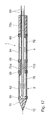
- Fig. 1 shows a longitudinal section through a first embodiment of a bipolar electrode assembly which is part of a surgical instrument for the electrothermal coagulation of tissue.
- the electrode assembly includes an electrically conductive front cylinder 10 that forms the distal end of the instrument, that is, remote from the user of the instrument.
- the front cylinder ends at its free end in a tip 12, which terminates conically pointed in the illustrated embodiment.
- To the front cylinder 10 includes a tubular outer conductor 20, which receives in its interior an insulation tube 30 through which a rod-shaped inner conductor 40 passes.
- the rod-shaped inner conductor 40 has at its distal end an external thread, which is screwed into a corresponding extending in the axial longitudinal direction internal thread and is electrically and mechanically connected by means of this screw 14 with the front cylinder 10.
- an insulator member 50 is arranged, which has a radial partition 52 between the front cylinder 10 and the distal end wall of the outer conductor 20 and the insulation tube 30. Externally on the dividing wall 52, the insulator element 50 merges into an enveloping wall 54 which, in the illustrated embodiment, tightly surrounds the outer surface of the front cylinder 10, but which, in an alternative embodiment, may also surround the outer surface of the outer conductor 20.
- the exposed outer surface of the front cylinder 10 forms a second electrode 4.
- the two electrodes - at the proximal end of the electrode assembly - a high frequency AC voltage source is connected when the bipolar electrode assembly in the treated human or animal tissue is introduced and the tissue is to be coagulated by the heat effect of the electric field.
- Fig. 2 shows a second embodiment of the bipolar electrode assembly according to the invention, in which in turn a front cylinder 10 terminates in a conical distal tip 12, in turn, a rod-shaped metallic inner conductor of an insulating tube 30 is surrounded, which in turn is surrounded by a metallic tubular outer conductor 20.
- an insulator member 50 is provided which has the shape of an annular body 58 and has a predetermined axial length, which keeps the front cylinder 10 and the outer conductor 20 at a distance.
- the front cylinder 10 is made of metal and serves as a cylindrical first electrode 2.
- the outer conductor 20 is also made of metal and serves as a cylindrical second electrode 4.
- the front cylinder 10 is connected by means of a screw 14 with the inner conductor 40.
- an RF AC voltage source is connected at the proximal end of the electrode assembly, between the outer conductor 20 and the inner conductor 40, an RF AC voltage source is connected when an electrothermal coagulation of surrounding tissue is to be performed,
- Fig. 3 shows a the Fig. 1 and 2 corresponding embodiment of a bipolar electrode arrangement in which the insulator element 50 is cup-shaped, wherein the cylindrical enveloping wall 54 is seated in a corresponding annular recess 11 of the front cylinder 10.
- the radial partition wall 52 of the insulator element 50 is guided proximally tubular - with the outer diameter of the insulating tube 30 - against the insulation tube 30, which ends a corresponding axial length in front of the distal end wall of the outer conductor 20.
- Fig. 4 shows a fourth embodiment of a bipolar electrode assembly 1 according to the invention, which largely according to the arrangement Fig. 1 corresponds, wherein the same parts are provided with the same reference numerals.
- a hollow channel through which passes an optical waveguide, the visible light leads to the distal tip 12 of the electrode assembly, when the optical fiber is fed proximally, for example, with visible laser light.
- the optical waveguide 60 includes a cladding 62 surrounding the photoconductive core 64. Around the mantle, a cladding can also be provided.
- Fig. 5 shows a further embodiment of the invention, which is largely the embodiment according to Fig. 4 However, wherein the front cylinder 10 has a wedge-shaped tip 12 at its distal end. Again, through the inner conductor 40 and thereafter also by the front cylinder 10, a central hollow channel is provided, through which an optical waveguide 60 runs with its sheath 62 and the core 64 to the distal tip 12 and the user of the electrode assembly - especially at a treatment of tissue in thin-walled body parts - each optically indicates the position of the distal tip 12 in the tissue.
- Fig. 6 shows a further embodiment of the bipolar electrode assembly 1 according to the invention, which is substantially the embodiment according to Fig. 2 or 4 equivalent.
- annular body 58 is provided, through which the inner conductor 40 extends axially to the front cylinder 10.
- the inner conductor 40 has a central hollow channel which extends to the distal end of the annular body 58 and contains an optical waveguide 60.
- the ring body 58 is formed of transparent or semi-transparent material and allows light to pass to the outside.
- annular body 58 In the area of the annular body 58, radial notches 42 are introduced into the inner conductor as far as into the core 64 of the optical waveguide, with the result that light passes radially outward from the inner conductor 40 and through the annular body 58 through this grinding in, so that the Operator, the position of the electric field, which is formed between the first electrode 2 and the second electrode 4, when 20 RF power is fed to the inner conductor 40 and the outer conductor, can be optically visible.
- the annular body 48 is preferably made of such a material or its surface has such a structure that the light 3 emerging from the optical waveguide passes outward as stray light.
- FIGS. 7 and 8 a further embodiment of the bipolar electrode assembly 1 is shown in longitudinal section and in cross section.
- a front cylinder 10 having a distal tip 12 is adjoined proximally by an elongated, electrically insulating support 70 which, in the illustrated embodiment, is formed as a metal tube 71 with an outer insulating layer 72.
- the metal tube is made of titanium or a titanium alloy
- the insulating layer 72 is made by anodizing the surface of the tube 71 as a thin ceramic layer.
- two strip-shaped electrodes 2, 4 are applied, which extend parallel to each other in the longitudinal direction of the carrier 70 and - on the circumference of the insulating layer, see.
- FIGS. 9 and 10 show a further embodiment of a bipolar electrode assembly 1 for a surgical instrument according to the invention, this embodiment being a development of the embodiment according to the FIGS. 7 and 8 represents.
- An elongated, uniform, insulating carrier 70 consists of a metallic tube 71, which is completely coated with an insulating layer 72 and has a central hollow channel all the way to the distal tip 12, through which an optical waveguide 60 extends to the distal tip 12.
- the optical waveguide 60 consists of a photoconductive core 64 and a jacket 62 surrounding this core.
- two strip-shaped electrodes 2, 4 are applied in the longitudinal direction, ie parallel to one another, which extend over the entire illustrated length of the carrier 70 and are mounted on the insulating layer 72.
- FIGS. 11 and 12 show a further embodiment of the invention, which is largely the embodiment according to the FIGS. 9 and 10 but no tubular metallic carrier 70 is used.
- the FIGS. 11 and 12 Rather show an embodiment in which an optical waveguide 60 with a core 64, a sheath 62 and a plastic sheath (cladding) 61 is provided at its free end with a wedge-shaped tip 12 and on the jacket or the cladding 61 in the longitudinal direction 2 strip-shaped Having electrodes 2, 4, which are arranged opposite one another on the circumference.
- the electrodes 2, 4 are applied in this embodiment as flexible layers, so that the entire bipolar electrode arrangement is flexible.
- FIGS. 13 and 14 cross-sections of bipolar electrode assemblies are shown in which the carrier 70 is formed of self-supporting, longitudinally extending metallic bar profiles 76.
- Fig. 13 are two rod profiles 76 made of metal spacer elements 60 insulating spaced.
- the rod profiles 76 each have approximately a cross section of a semicircular surface and form elongated electrodes 2, 4 running in the longitudinal direction of the electrode arrangement.
- the spacer elements 60 are designed as light conductors 60 in the illustrated embodiment.
- light guides are used on the side surfaces, in which light can also emerge sideways, so that the surgeon recognizes light signals along the length of the electrodes 2, 4 when using such a bipolar electrode arrangement, which indicate the position of the electrodes 2, 4 over their length ,
- Fig. 14 is one of the Fig. 13 corresponding embodiment shown in which two rod-shaped, self-supporting metallic rod profiles 76, which have the shape of Rohrwandungsabroughen in cross section, on the outer sheath of an optical waveguide are applied in the longitudinal direction and fixed there and the electrodes 2, 4 form.
- the optical waveguide 16 in the illustrated form between the outer casing 61 and the core 64 still has a jacket 62.
- FIGS. 15 and 16 An embodiment of a bipolar electrode arrangement 1 is shown, in which a front cylinder 10 is provided at the distal end of the instrument with a distal conical tip 12, to which an elongated, electrically insulating support 70 connects. On the carrier 70, two pipe sections 82, 84 are pushed and secured via a spacer 83 made of insulating material, which form cylindrical electrodes 2, 4.
- a central hollow channel 76 which opens into a recess 14 in the front cylinder 10 and receives a temperature sensor 100 which is surrounded by a plastic or adhesive bed 102 and secured there and via a line 104, a signal to the emits proximal end of the instrument, which corresponds to the temperature of the front cylinder 10.
- connecting lines 90 which are connected by the carrier 70 to the electrodes 2, 4 and can be connected to the proximal HF generator.
- the axial length L1 of the first electrode 2 and the axial length L2 of the second electrode 4 are - in all the illustrated embodiments - greater than the distance A between the two electrodes 2, 4.
- the distance A is preferably of the order of the outer diameter of the electrodes. 2 , 4.
- R is the radius of the generally circular-cylindrical electrode arrangement.
- L1 L2.
- a bipolar electrode assembly in which a front cylinder 10 having a tapered distal tip 12 is secured to the end of a first tube section 82, which first tube section 82 is secured to a first carrier 70a with one end portion.
- a second tube section 84 is seated with one end portion on the first carrier 70a and with its other end portion on a second carrier 70b.
- the carriers 70a and 70b each have a hollow channel 76 whose axis is aligned with the axis of the pipe sections 82, 84.
- the pipe sections 82, 84 are the cylindrical electrodes 2, 4 are.
- a flushing tube 110 is passed, the fluid emits at its distal end, which then flows back into contact with the inner wall of the pipe sections 82, 84 through the hollow channel 76 to the proximal end and the two pipe sections 82, 84 cools.
- the pipe sections 82, 84 provided on its outer surface with an annular insulating layer, so that at these points by the liquid is only cooled to a lesser extent, there is no undesirable elevation of the electrode temperature, which leads to undesired caking of the tissue on the electrodes or to dehydration of the adjacent tissue, and thus to an increase in impedance in this tissue and to an interruption of the electrical current through the tissue comes.
- the cooling with a corresponding cooling liquid has the consequence that the tissue at the contact surface to the electrodes does not exceed a predetermined temperature, and that the hot spot of the coagulation is a few millimeters away from the electrodes.
- FIGS. 18 and 19 correspond to the embodiment according to FIG Fig. 17 However, wherein the front cylinder 10 in FIGS. 18 and 19 is made of metal and passes directly into the first pipe section 82, the first electrode, and wherein the front cylinder 10 in Fig. 19 frontally rounded.
- the lengths L1 and L2 of the electrodes 2, 4 are dimensioned such that the area formed by the front cylinder and the first electrode is equal to or smaller than the surface of the second electrode.
- Fig. 22 an embodiment of the bipolar electrode arrangement is shown, which is largely that of Fig. 17 however, the second pipe section 84, which constitutes the second electrode 4, is substantially longer than the first pipe section 82, which is the first electrode 2.
- the second tube section 84 ends at the proximal end of the instrument, a further carrier at the end of the proximal instrument can therefore be dispensed with.
- the axial length of the second electrode 4 is limited by the fact that on the proximal end portion of the second pipe section 84, an insulating layer 87 is applied, which covers the metal surface of the second pipe section 84 at this point, for example by means of a ceramic coating.
- thermoelectric coagulation then forms between the metallic, cylindrical electrodes 2, 4. Also in this Embodiment, the end portions of the pipe sections 82, 84, which are surrounded on the inside either by the insulating material of the front cylinder 10 or the insulating material of the carrier 70, also coated on the outer surface with an insulating layer 86, at these points - due to the lack of cooling - a prevent overheating of the electrodes.
- a frontally rounded front cylinder 10 merges into a first tube section 82, which is fastened with its proximal end to an insulating support.
- a metal layer 88 is provided on the insulating support.
- the tube 82 forms the cylindrical first electrode 2
- the metal coating on the carrier 70 forms the cylindrical second electrode 4.
- Carrier 70 and tube 82 are each formed with a central hollow channel 76, 77, through - to just before the distal end of the front cylinder 10 - a flushing tube 110 passes, which delivers liquid at the distal end, which cools the first electrode in contact with the inner surface of the first electrode 2.
- an insulating layer 86 is laid to prevent local overheating of the electrode 2 at this point, since this point is not contacted by liquid on the inside.
- the front cylinder 10 is formed of metal, its rounding at the distal end is advantageously suitable for the treatment of peripheral tumors, in which a layer of coagulated tissue forms in front of the distal end of the instrument.
- FIGS. 20 and 21 Further embodiments of a bipolar electrode arrangement are specified.
- the basic structure in both cases provides a front cylinder 10 made of metal or insulating material, to which a tube 82 connects, which is attached to the proximal end portion of a carrier 70.
- the carrier 70 and the tube 72 each have a central hollow channel 76 or 77, through which a flushing tube 110 is guided, which emits liquid at its distal end, which runs back into contact with the inner surface of the tube 82 then to the proximal end of the instrument.
- a flushing tube 110 is guided, which emits liquid at its distal end, which runs back into contact with the inner surface of the tube 82 then to the proximal end of the instrument.
- the distal tube section 82 has an outer metallic surface and forms the cylindrical first electrode 2
- the proximal tube section 84 adjoining thereto is provided with an insulating layer 87, to which at the proximal end a metal layer 88 is applied, which forms the cylindrical second electrode 4.
- the distal tube section 82 is provided with an insulating layer 87 to which - at the distal end - a metal layer 88 is applied, which forms the first electrode;
- the proximal tube section forms the second electrode 4.
- a carrier 70 extends from a metal tube to a wedge-shaped distal tip 12 and has the shape of a cannula.
- an insulating layer 87 is applied to the carrier 70, which is provided in its proximal region with a metal coating 88.
- the distal tip 12 is followed by the cylindrical first electrode 2 with its metallic outer surface, the metal coating 88 at the proximal region forming the cylindrical second electrode 4.
- a hollow channel 76 extends through the tube and is open at the distal end for flushing can serve drugs.
- the Fig. 25 and 26 represent variants of the embodiment, which in Fig. 24 is shown.
- the embodiment according to Fig. 25 deviates from that of the Fig. 24 in so far as the insulating layer 87 applied to the metal carrier 70 and the metal layer 88 applied to the insulating layer 87 each have a distal edge which corresponds to the wedge-shaped distal tip 12 of the carrier 70.
- a metallic rod instead of the tubular support 70 of Fig. 24 , which has a conical distal tip, and on which the insulating layer 87 is applied, on which the metal layer 88 is subsequently arranged.
- All illustrated embodiments of the bipolar electrode assembly 1 have a substantially circular cross-section with radius R and over its length a homogeneous cross-section as possible. Discrepancies in the outer diameter are kept as small as possible in order to be able to introduce the electrode arrangement into the tissue with ease.
- the axial length of the electrodes is larger in all the illustrated embodiments than the distance of the electrodes, which is substantially of the order of the outer diameter. In this dimensioning, there is an advantageous local concentration of the coagulation process and a sufficient strength of the electric field.
- the carrier 70 may be either flexible or rigid.
- a flushing tube dispenses flushing liquid at the distal end of a cavity
- the instrument is cooled in order to prevent the tissue from drying out at the electrodes and to be able to apply stronger electrical fields in order to achieve an optimal coagulation course without the tissue caking on the electrodes.
- Fig. 27 shows a front cylinder 10, which consists for example of aluminum or titanium or a titanium alloy and was provided by anodic oxidation, ie a proximal end portion with a ceramic layer which forms the insulating member 50, the partition wall 52 is formed at the proximal end of the front cylinder, and its Hüllwand 54 extends outwardly around an axial longitudinal portion of the front cylinder.
- a front cylinder 10 which consists for example of aluminum or titanium or a titanium alloy and was provided by anodic oxidation, ie a proximal end portion with a ceramic layer which forms the insulating member 50, the partition wall 52 is formed at the proximal end of the front cylinder, and its Hüllwand 54 extends outwardly around an axial longitudinal portion of the front cylinder.
- FIGS. 28 and 29 show an end portion, designed as a spiral spring 92, of a connecting line 90, which according to FIG Fig. 25 is inserted into the hollow channel 77 of a metal tube 80 and rests against the inner surface of the tube 80 under radial pressure and this contacted.
- an insulating layer 87 is shown on the metal tube 80.
Landscapes
- Health & Medical Sciences (AREA)
- Life Sciences & Earth Sciences (AREA)
- Surgery (AREA)
- Engineering & Computer Science (AREA)
- Plasma & Fusion (AREA)
- General Health & Medical Sciences (AREA)
- Otolaryngology (AREA)
- Physics & Mathematics (AREA)
- Veterinary Medicine (AREA)
- Biomedical Technology (AREA)
- Heart & Thoracic Surgery (AREA)
- Medical Informatics (AREA)
- Molecular Biology (AREA)
- Animal Behavior & Ethology (AREA)
- Nuclear Medicine, Radiotherapy & Molecular Imaging (AREA)
- Public Health (AREA)
- Cardiology (AREA)
- Surgical Instruments (AREA)
Applications Claiming Priority (3)
| Application Number | Priority Date | Filing Date | Title |
|---|---|---|---|
| DE19858599 | 1998-12-18 | ||
| EP05103696A EP1568332B1 (fr) | 1998-12-18 | 1999-12-17 | Ensemble-electrode pour un instrument chirurgical de coagulation electrothermique de tissu |
| EP99966974A EP1139897B1 (fr) | 1998-12-18 | 1999-12-17 | Ensemble electrode pour un instrument chirurgical servant a la coagulation electrothermique de tissu |
Related Parent Applications (2)
| Application Number | Title | Priority Date | Filing Date |
|---|---|---|---|
| EP99966974.0 Division | 1999-12-17 | ||
| EP05103696.0 Division | 2005-05-03 |
Publications (2)
| Publication Number | Publication Date |
|---|---|
| EP2206475A2 true EP2206475A2 (fr) | 2010-07-14 |
| EP2206475A3 EP2206475A3 (fr) | 2010-11-17 |
Family
ID=7891651
Family Applications (3)
| Application Number | Title | Priority Date | Filing Date |
|---|---|---|---|
| EP05103696A Expired - Lifetime EP1568332B1 (fr) | 1998-12-18 | 1999-12-17 | Ensemble-electrode pour un instrument chirurgical de coagulation electrothermique de tissu |
| EP10158860A Withdrawn EP2206475A3 (fr) | 1998-12-18 | 1999-12-17 | Ensemble-electrode pour un instrument chirurgical de coagulation electrothermique de tissu |
| EP99966974A Expired - Lifetime EP1139897B1 (fr) | 1998-12-18 | 1999-12-17 | Ensemble electrode pour un instrument chirurgical servant a la coagulation electrothermique de tissu |
Family Applications Before (1)
| Application Number | Title | Priority Date | Filing Date |
|---|---|---|---|
| EP05103696A Expired - Lifetime EP1568332B1 (fr) | 1998-12-18 | 1999-12-17 | Ensemble-electrode pour un instrument chirurgical de coagulation electrothermique de tissu |
Family Applications After (1)
| Application Number | Title | Priority Date | Filing Date |
|---|---|---|---|
| EP99966974A Expired - Lifetime EP1139897B1 (fr) | 1998-12-18 | 1999-12-17 | Ensemble electrode pour un instrument chirurgical servant a la coagulation electrothermique de tissu |
Country Status (8)
| Country | Link |
|---|---|
| US (3) | US6723094B1 (fr) |
| EP (3) | EP1568332B1 (fr) |
| JP (2) | JP4583604B2 (fr) |
| AT (2) | ATE507788T1 (fr) |
| AU (1) | AU2284100A (fr) |
| DE (2) | DE59915265D1 (fr) |
| ES (1) | ES2243090T3 (fr) |
| WO (1) | WO2000036985A2 (fr) |
Families Citing this family (190)
| Publication number | Priority date | Publication date | Assignee | Title |
|---|---|---|---|---|
| DE102004033595A1 (de) * | 2004-07-07 | 2006-02-16 | Celon Ag Medical Instruments | Bipolare Koagulationselektrode |
| GB0223348D0 (en) * | 2002-10-08 | 2002-11-13 | Gyrus Medical Ltd | A surgical instrument |
| JP2004500207A (ja) | 2000-03-06 | 2004-01-08 | ティシューリンク・メディカル・インコーポレーテッド | 流体配給システム及び電気外科用器具コントローラ |
| US6953461B2 (en) | 2002-05-16 | 2005-10-11 | Tissuelink Medical, Inc. | Fluid-assisted medical devices, systems and methods |
| US6689131B2 (en) | 2001-03-08 | 2004-02-10 | Tissuelink Medical, Inc. | Electrosurgical device having a tissue reduction sensor |
| US8048070B2 (en) | 2000-03-06 | 2011-11-01 | Salient Surgical Technologies, Inc. | Fluid-assisted medical devices, systems and methods |
| US6558385B1 (en) | 2000-09-22 | 2003-05-06 | Tissuelink Medical, Inc. | Fluid-assisted medical device |
| US7811282B2 (en) | 2000-03-06 | 2010-10-12 | Salient Surgical Technologies, Inc. | Fluid-assisted electrosurgical devices, electrosurgical unit with pump and methods of use thereof |
| DE20009426U1 (de) | 2000-05-26 | 2001-10-31 | Desinger, Kai, Dr., 12157 Berlin | Chirurgisches Instrument |
| US7789876B2 (en) * | 2000-08-14 | 2010-09-07 | Tyco Healthcare Group, Lp | Method and apparatus for positioning a catheter relative to an anatomical junction |
| US6974457B2 (en) * | 2001-01-11 | 2005-12-13 | C.R. Bard Inc. | Ablation catheter |
| DE10128701B4 (de) * | 2001-06-07 | 2005-06-23 | Celon Ag Medical Instruments | Sondenanordnung |
| EP2275050A1 (fr) | 2001-09-05 | 2011-01-19 | Salient Surgical Technologies, Inc. | Dispositifs, procédés et systèmes chirurgicaux assistés par un fluide |
| AU2002357166A1 (en) | 2001-12-12 | 2003-06-23 | Tissuelink Medical, Inc. | Fluid-assisted medical devices, systems and methods |
| US6740084B2 (en) * | 2001-12-18 | 2004-05-25 | Ethicon, Inc. | Method and device to enhance RF electrode performance |
| US7197363B2 (en) | 2002-04-16 | 2007-03-27 | Vivant Medical, Inc. | Microwave antenna having a curved configuration |
| US8361067B2 (en) | 2002-09-30 | 2013-01-29 | Relievant Medsystems, Inc. | Methods of therapeutically heating a vertebral body to treat back pain |
| JP2006504472A (ja) | 2002-10-29 | 2006-02-09 | ティシューリンク・メディカル・インコーポレーテッド | 流体補助電気外科手術鋏及び方法 |
| KR100466866B1 (ko) * | 2003-04-24 | 2005-01-24 | 전명기 | 생체조직을 응고괴사시키는 고주파 전기수술기용 전극 |
| GB2403148C2 (en) | 2003-06-23 | 2013-02-13 | Microsulis Ltd | Radiation applicator |
| DE10328397A1 (de) * | 2003-06-25 | 2005-01-20 | Exogen Medizintechnik Ag | Elektroden insbesondere zur Behandlung von Tumorerkrankungen mit Hilfe des elektrischen Stroms |
| JP4342855B2 (ja) * | 2003-07-11 | 2009-10-14 | 三井金属鉱業株式会社 | 軽油の液種識別装置および軽油の液種識別方法 |
| DE10332564A1 (de) * | 2003-07-11 | 2005-01-27 | Celon Ag Medical Instruments | Chirurgische Sonde |
| US7011656B2 (en) * | 2003-11-14 | 2006-03-14 | Starion Instruments Corporation | Thermal cautery devices with improved heating profiles |
| US7727232B1 (en) | 2004-02-04 | 2010-06-01 | Salient Surgical Technologies, Inc. | Fluid-assisted medical devices and methods |
| DE102005013714A1 (de) | 2004-04-07 | 2005-12-22 | Carl Zeiss Meditec Ag | Elektrische Sonde für die Mikrochirurgie |
| US20050283149A1 (en) * | 2004-06-08 | 2005-12-22 | Thorne Jonathan O | Electrosurgical cutting instrument |
| US8409219B2 (en) | 2004-06-18 | 2013-04-02 | Medtronic, Inc. | Method and system for placement of electrical lead inside heart |
| GB2415630C2 (en) | 2004-07-02 | 2007-03-22 | Microsulis Ltd | Radiation applicator and method of radiating tissue |
| US7824408B2 (en) | 2004-08-05 | 2010-11-02 | Tyco Healthcare Group, Lp | Methods and apparatus for coagulating and/or constricting hollow anatomical structures |
| JP5046931B2 (ja) * | 2004-08-05 | 2012-10-10 | タイコ ヘルスケア グループ リミテッド パートナーシップ | 中空の解剖学的構造を凝固させかつ/または狭窄させる方法および装置 |
| US7166104B2 (en) * | 2004-08-30 | 2007-01-23 | Boston Scientific Scimed, Inc. | Composite material braided insulator |
| WO2006025366A1 (fr) * | 2004-09-01 | 2006-03-09 | Jms Co., Ltd. | Système de traitement des varices |
| US20070016272A1 (en) | 2004-09-27 | 2007-01-18 | Thompson Russell B | Systems and methods for treating a hollow anatomical structure |
| US20070093802A1 (en) * | 2005-10-21 | 2007-04-26 | Danek Christopher J | Energy delivery devices and methods |
| US7625372B2 (en) * | 2005-02-23 | 2009-12-01 | Vnus Medical Technologies, Inc. | Methods and apparatus for coagulating and/or constricting hollow anatomical structures |
| DE102005023303A1 (de) * | 2005-05-13 | 2006-11-16 | Celon Ag Medical Instruments | Biegeweiche Applikationsvorrichtung zur Hochfrequenztherapie von biologischem Gewebe |
| GB2434314B (en) | 2006-01-03 | 2011-06-15 | Microsulis Ltd | Microwave applicator with dipole antenna |
| US20070179575A1 (en) * | 2005-07-21 | 2007-08-02 | Esch Brady D | Thermal therapeutic catheter with location detection enhancement |
| DE102005040386A1 (de) * | 2005-08-25 | 2007-03-01 | Olympus Winter & Ibe Gmbh | Elektrochirurgisches Schaftinstrument mit Elektrodenleitung |
| US20070244371A1 (en) * | 2006-04-04 | 2007-10-18 | Nguyen Hoa D | Phlebectomy illumination device and methods |
| WO2008057805A1 (fr) | 2006-11-01 | 2008-05-15 | Bovie Medical Corporation | Sonde d'ablation bipolaire comportant des électrodes poreuses permettant la délivrance d'un fluide électroconducteur |
| CN100594008C (zh) | 2007-01-16 | 2010-03-17 | 盛林 | 微波消融水刀 |
| US8211099B2 (en) | 2007-01-31 | 2012-07-03 | Tyco Healthcare Group Lp | Thermal feedback systems and methods of using the same |
| BE1017481A3 (nl) * | 2007-03-02 | 2008-10-07 | Care Systems Nv F | Naald voor het thermisch coaguleren van bloedvaten. |
| US8216233B2 (en) * | 2007-03-23 | 2012-07-10 | Salient Surgical Technologies, Inc. | Surgical devices and methods of use thereof |
| JP4683434B2 (ja) * | 2007-03-27 | 2011-05-18 | 日本ライフライン株式会社 | 焼灼用穿刺針 |
| US7777130B2 (en) * | 2007-06-18 | 2010-08-17 | Vivant Medical, Inc. | Microwave cable cooling |
| WO2009059052A2 (fr) | 2007-11-03 | 2009-05-07 | Boston Scientific Scimed, Inc. | Sonde électrochirurgicale bipolaire présentant des éléments conducteurs isolés se chevauchant |
| US8292880B2 (en) | 2007-11-27 | 2012-10-23 | Vivant Medical, Inc. | Targeted cooling of deployable microwave antenna |
| US8221409B2 (en) * | 2007-12-21 | 2012-07-17 | St. Jude Medical, Atrial Fibrillation Division, Inc. | Thermally insulated irrigation catheter assembly |
| US8353907B2 (en) | 2007-12-21 | 2013-01-15 | Atricure, Inc. | Ablation device with internally cooled electrodes |
| US8998892B2 (en) * | 2007-12-21 | 2015-04-07 | Atricure, Inc. | Ablation device with cooled electrodes and methods of use |
| US7642451B2 (en) | 2008-01-23 | 2010-01-05 | Vivant Medical, Inc. | Thermally tuned coaxial cable for microwave antennas |
| US8435237B2 (en) | 2008-01-29 | 2013-05-07 | Covidien Lp | Polyp encapsulation system and method |
| US8353902B2 (en) | 2008-01-31 | 2013-01-15 | Vivant Medical, Inc. | Articulating ablation device and method |
| US8221418B2 (en) | 2008-02-07 | 2012-07-17 | Tyco Healthcare Group Lp | Endoscopic instrument for tissue identification |
| DE102008044887A1 (de) * | 2008-04-30 | 2009-11-05 | Hebumedical Gmbh | Bipolarelektrodeneinrichtung, Handgriff und bipolares System für elektrochirurgische Anwendungen |
| US8328804B2 (en) | 2008-07-24 | 2012-12-11 | Covidien Lp | Suction coagulator |
| US8211098B2 (en) * | 2008-08-25 | 2012-07-03 | Vivant Medical, Inc. | Microwave antenna assembly having a dielectric body portion with radial partitions of dielectric material |
| US8251987B2 (en) | 2008-08-28 | 2012-08-28 | Vivant Medical, Inc. | Microwave antenna |
| CA2957010C (fr) | 2008-09-26 | 2017-07-04 | Relievant Medsystems, Inc. | Systemes et procedes pour piloter un instrument a travers un os |
| US10028753B2 (en) | 2008-09-26 | 2018-07-24 | Relievant Medsystems, Inc. | Spine treatment kits |
| US8600472B2 (en) * | 2008-12-30 | 2013-12-03 | Biosense Webster (Israel), Ltd. | Dual-purpose lasso catheter with irrigation using circumferentially arranged ring bump electrodes |
| US8475450B2 (en) | 2008-12-30 | 2013-07-02 | Biosense Webster, Inc. | Dual-purpose lasso catheter with irrigation |
| US8945117B2 (en) * | 2009-02-11 | 2015-02-03 | Boston Scientific Scimed, Inc. | Insulated ablation catheter devices and methods of use |
| US8197473B2 (en) | 2009-02-20 | 2012-06-12 | Vivant Medical, Inc. | Leaky-wave antennas for medical applications |
| US9277969B2 (en) | 2009-04-01 | 2016-03-08 | Covidien Lp | Microwave ablation system with user-controlled ablation size and method of use |
| DE202009018056U1 (de) * | 2009-04-16 | 2010-12-30 | Erbe Elektromedizin Gmbh | Endoskopisches Chirurgieinstrument |
| US9131977B2 (en) | 2009-04-17 | 2015-09-15 | Domain Surgical, Inc. | Layered ferromagnetic coated conductor thermal surgical tool |
| US9107666B2 (en) | 2009-04-17 | 2015-08-18 | Domain Surgical, Inc. | Thermal resecting loop |
| US8372066B2 (en) | 2009-04-17 | 2013-02-12 | Domain Surgical, Inc. | Inductively heated multi-mode surgical tool |
| US20100280328A1 (en) * | 2009-05-01 | 2010-11-04 | Tyco Healthcare Group, Lp | Methods and systems for illumination during phlebectomy procedures |
| US8246615B2 (en) | 2009-05-19 | 2012-08-21 | Vivant Medical, Inc. | Tissue impedance measurement using a secondary frequency |
| US8292881B2 (en) | 2009-05-27 | 2012-10-23 | Vivant Medical, Inc. | Narrow gauge high strength choked wet tip microwave ablation antenna |
| US8552915B2 (en) | 2009-06-19 | 2013-10-08 | Covidien Lp | Microwave ablation antenna radiation detector |
| DE102009048312B4 (de) * | 2009-07-07 | 2017-05-11 | Erbe Elektromedizin Gmbh | Elektrochirurgisches Instrument und Verfahren zur Herstellung eines elektrochirurgischen Instruments |
| US8328799B2 (en) | 2009-08-05 | 2012-12-11 | Vivant Medical, Inc. | Electrosurgical devices having dielectric loaded coaxial aperture with distally positioned resonant structure |
| US8394087B2 (en) | 2009-09-24 | 2013-03-12 | Vivant Medical, Inc. | Optical detection of interrupted fluid flow to ablation probe |
| US9024237B2 (en) | 2009-09-29 | 2015-05-05 | Covidien Lp | Material fusing apparatus, system and method of use |
| US8568398B2 (en) | 2009-09-29 | 2013-10-29 | Covidien Lp | Flow rate monitor for fluid cooled microwave ablation probe |
| GB2474233A (en) | 2009-10-06 | 2011-04-13 | Uk Investments Associates Llc | Cooling pump comprising a detachable head portion |
| US8382750B2 (en) | 2009-10-28 | 2013-02-26 | Vivant Medical, Inc. | System and method for monitoring ablation size |
| US8430871B2 (en) | 2009-10-28 | 2013-04-30 | Covidien Lp | System and method for monitoring ablation size |
| US8469953B2 (en) | 2009-11-16 | 2013-06-25 | Covidien Lp | Twin sealing chamber hub |
| US8394092B2 (en) | 2009-11-17 | 2013-03-12 | Vivant Medical, Inc. | Electromagnetic energy delivery devices including an energy applicator array and electrosurgical systems including same |
| US8920415B2 (en) * | 2009-12-16 | 2014-12-30 | Biosense Webster (Israel) Ltd. | Catheter with helical electrode |
| US8608735B2 (en) | 2009-12-30 | 2013-12-17 | Biosense Webster (Israel) Ltd. | Catheter with arcuate end section |
| US8936631B2 (en) * | 2010-01-04 | 2015-01-20 | Covidien Lp | Apparatus and methods for treating hollow anatomical structures |
| US20110190763A1 (en) * | 2010-01-29 | 2011-08-04 | Medtronic, Inc. | Needle Design for Recording Monophasic Action Potential and Delivery of Therapy |
| US8491579B2 (en) | 2010-02-05 | 2013-07-23 | Covidien Lp | Electrosurgical devices with choke shorted to biological tissue |
| US20110213353A1 (en) | 2010-02-26 | 2011-09-01 | Lee Anthony C | Tissue Ablation System With Internal And External Radiation Sources |
| US8409188B2 (en) | 2010-03-26 | 2013-04-02 | Covidien Lp | Ablation devices with adjustable radiating section lengths, electrosurgical systems including same, and methods of adjusting ablation fields using same |
| US9017319B2 (en) | 2011-01-05 | 2015-04-28 | Covidien Lp | Energy-delivery devices with flexible fluid-cooled shaft, inflow/outflow junctions suitable for use with same, and systems including same |
| US9770294B2 (en) | 2011-01-05 | 2017-09-26 | Covidien Lp | Energy-delivery devices with flexible fluid-cooled shaft, inflow/outflow junctions suitable for use with same, and systems including same |
| US8932281B2 (en) | 2011-01-05 | 2015-01-13 | Covidien Lp | Energy-delivery devices with flexible fluid-cooled shaft, inflow/outflow junctions suitable for use with same, and systems including same |
| US9011421B2 (en) * | 2011-01-05 | 2015-04-21 | Covidien Lp | Energy-delivery devices with flexible fluid-cooled shaft, inflow/outflow junctions suitable for use with same, and systems including same |
| JP2011098211A (ja) * | 2011-01-15 | 2011-05-19 | Japan Lifeline Co Ltd | 焼灼用穿刺針 |
| US10335230B2 (en) | 2011-03-09 | 2019-07-02 | Covidien Lp | Systems for thermal-feedback-controlled rate of fluid flow to fluid-cooled antenna assembly and methods of directing energy to tissue using same |
| US8932279B2 (en) * | 2011-04-08 | 2015-01-13 | Domain Surgical, Inc. | System and method for cooling of a heated surgical instrument and/or surgical site and treating tissue |
| JP2014516614A (ja) | 2011-04-08 | 2014-07-17 | コビディエン エルピー | 自然管腔又は人口管腔のための可撓性マイクロ波カテーテル |
| KR101248959B1 (ko) * | 2011-05-12 | 2013-04-01 | 신경민 | 플렉시블관이 구비되는 고주파 열치료용 전극장치 |
| US9220433B2 (en) | 2011-06-30 | 2015-12-29 | Biosense Webster (Israel), Ltd. | Catheter with variable arcuate distal section |
| US10743932B2 (en) | 2011-07-28 | 2020-08-18 | Biosense Webster (Israel) Ltd. | Integrated ablation system using catheter with multiple irrigation lumens |
| US9662169B2 (en) | 2011-07-30 | 2017-05-30 | Biosense Webster (Israel) Ltd. | Catheter with flow balancing valve |
| AU2015201725B2 (en) * | 2011-07-30 | 2017-03-02 | Biosense Webster (Israel), Ltd. | Catheter with flow balancing valve |
| US9526558B2 (en) | 2011-09-13 | 2016-12-27 | Domain Surgical, Inc. | Sealing and/or cutting instrument |
| JP2015506729A (ja) | 2011-12-06 | 2015-03-05 | ドメイン・サージカル,インコーポレーテッド | 外科手術器具への電力供給を制御するシステム及び方法 |
| WO2013101772A1 (fr) | 2011-12-30 | 2013-07-04 | Relievant Medsystems, Inc. | Systèmes et méthodes de traitement de douleur dorsale |
| US10076383B2 (en) | 2012-01-25 | 2018-09-18 | Covidien Lp | Electrosurgical device having a multiplexer |
| US9192308B2 (en) | 2012-03-27 | 2015-11-24 | Covidien Lp | Microwave-shielded tissue sensor probe |
| US8945113B2 (en) | 2012-04-05 | 2015-02-03 | Covidien Lp | Electrosurgical tissue ablation systems capable of detecting excessive bending of a probe and alerting a user |
| US8920410B2 (en) | 2012-05-04 | 2014-12-30 | Covidien Lp | Peripheral switching device for microwave energy platforms |
| US9168178B2 (en) | 2012-05-22 | 2015-10-27 | Covidien Lp | Energy-delivery system and method for controlling blood loss from wounds |
| US20130324910A1 (en) | 2012-05-31 | 2013-12-05 | Covidien Lp | Ablation device with drug delivery component and biopsy tissue-sampling component |
| CN104487013B (zh) | 2012-06-22 | 2017-06-20 | 柯惠有限合伙公司 | 微波消融系统和测量微波消融系统中温度的方法 |
| US9332959B2 (en) | 2012-06-26 | 2016-05-10 | Covidien Lp | Methods and systems for enhancing ultrasonic visibility of energy-delivery devices within tissue |
| US9192426B2 (en) | 2012-06-26 | 2015-11-24 | Covidien Lp | Ablation device having an expandable chamber for anchoring the ablation device to tissue |
| US9066681B2 (en) | 2012-06-26 | 2015-06-30 | Covidien Lp | Methods and systems for enhancing ultrasonic visibility of energy-delivery devices within tissue |
| US9901398B2 (en) | 2012-06-29 | 2018-02-27 | Covidien Lp | Microwave antenna probes |
| US9192439B2 (en) | 2012-06-29 | 2015-11-24 | Covidien Lp | Method of manufacturing a surgical instrument |
| US9439712B2 (en) | 2012-07-12 | 2016-09-13 | Covidien Lp | Heat-distribution indicators, thermal zone indicators, electrosurgical systems including same and methods of directing energy to tissue using same |
| US10537748B2 (en) | 2012-07-23 | 2020-01-21 | Koninklijke Philips N.V. | Combined brachytherapy and electrochemotherapy catheters |
| US9375252B2 (en) | 2012-08-02 | 2016-06-28 | Covidien Lp | Adjustable length and/or exposure electrodes |
| US9044254B2 (en) | 2012-08-07 | 2015-06-02 | Covidien Lp | Microwave ablation catheter and method of utilizing the same |
| US10588691B2 (en) | 2012-09-12 | 2020-03-17 | Relievant Medsystems, Inc. | Radiofrequency ablation of tissue within a vertebral body |
| US9370392B2 (en) | 2012-10-02 | 2016-06-21 | Covidien Lp | Heat-sensitive optical probes |
| US9743975B2 (en) | 2012-10-02 | 2017-08-29 | Covidien Lp | Thermal ablation probe for a medical device |
| US9668802B2 (en) | 2012-10-02 | 2017-06-06 | Covidien Lp | Devices and methods for optical detection of tissue contact |
| US9522033B2 (en) | 2012-10-02 | 2016-12-20 | Covidien Lp | Devices and methods for optical detection of tissue contact |
| US9662165B2 (en) | 2012-10-02 | 2017-05-30 | Covidien Lp | Device and method for heat-sensitive agent application |
| US9993283B2 (en) * | 2012-10-02 | 2018-06-12 | Covidien Lp | Selectively deformable ablation device |
| CA2889478C (fr) | 2012-11-05 | 2020-11-24 | Relievant Medsystems, Inc. | Systeme et methodes de creation de chemins incurves a travers un os et de modulation des nerfs au sein de l'os |
| US9901399B2 (en) | 2012-12-17 | 2018-02-27 | Covidien Lp | Ablation probe with tissue sensing configuration |
| CA2899509A1 (fr) | 2013-03-29 | 2014-10-02 | Covidien Lp | Applicateurs d'ablation a micro-ondes coaxiaux a abaissement et procedes pour leur fabrication |
| EP2815713B1 (fr) | 2013-06-20 | 2015-08-12 | Erbe Elektromedizin GmbH | Instrument électrochirurgical doté d'un conducteur lumineux |
| US9724151B2 (en) | 2013-08-08 | 2017-08-08 | Relievant Medsystems, Inc. | Modulating nerves within bone using bone fasteners |
| US9814844B2 (en) | 2013-08-27 | 2017-11-14 | Covidien Lp | Drug-delivery cannula assembly |
| ES2865049T3 (es) | 2013-09-06 | 2021-10-14 | Covidien Lp | Catéter, mango y sistema de ablación por microondas |
| US10631914B2 (en) | 2013-09-30 | 2020-04-28 | Covidien Lp | Bipolar electrosurgical instrument with movable electrode and related systems and methods |
| CN105873534A (zh) | 2013-11-13 | 2016-08-17 | 美国奥林匹斯外科技术吉鲁斯阿克米公司 | 纤维瘤消融定位装置和方法 |
| KR101522662B1 (ko) * | 2013-11-27 | 2015-05-27 | 주식회사 스타메드 | 고주파 열치료용 전극장치 |
| US10357306B2 (en) | 2014-05-14 | 2019-07-23 | Domain Surgical, Inc. | Planar ferromagnetic coated surgical tip and method for making |
| US10624697B2 (en) | 2014-08-26 | 2020-04-21 | Covidien Lp | Microwave ablation system |
| US10813691B2 (en) | 2014-10-01 | 2020-10-27 | Covidien Lp | Miniaturized microwave ablation assembly |
| WO2016061002A1 (fr) | 2014-10-13 | 2016-04-21 | Boston Scientific Scimed Inc. | Diagnostic et traitement de tissus à l'aide de mini-électrodes |
| GB201418479D0 (en) * | 2014-10-17 | 2014-12-03 | Creo Medical Ltd | Cable for conveying radiofrequency and/or microwave frequency energy to an electrosurgical instrument |
| EP4316361A3 (fr) | 2014-10-24 | 2024-05-01 | Boston Scientific Scimed Inc. | Dispositifs médicaux dotés d'un ensemble d'électrode souple couplé à une pointe d'ablation |
| US10080600B2 (en) | 2015-01-21 | 2018-09-25 | Covidien Lp | Monopolar electrode with suction ability for CABG surgery |
| CN113208725B (zh) | 2015-11-25 | 2024-05-31 | 捷锐士阿希迈公司(以奥林巴斯美国外科技术名义) | 执行器和电外科器械 |
| US10813692B2 (en) | 2016-02-29 | 2020-10-27 | Covidien Lp | 90-degree interlocking geometry for introducer for facilitating deployment of microwave radiating catheter |
| US11510730B2 (en) * | 2016-03-26 | 2022-11-29 | Paul Joseph Weber | Apparatus and methods for minimally invasive dissection and modification of tissues |
| US11065053B2 (en) | 2016-08-02 | 2021-07-20 | Covidien Lp | Ablation cable assemblies and a method of manufacturing the same |
| US10376309B2 (en) | 2016-08-02 | 2019-08-13 | Covidien Lp | Ablation cable assemblies and a method of manufacturing the same |
| US11197715B2 (en) | 2016-08-02 | 2021-12-14 | Covidien Lp | Ablation cable assemblies and a method of manufacturing the same |
| US11000332B2 (en) | 2016-08-02 | 2021-05-11 | Covidien Lp | Ablation cable assemblies having a large diameter coaxial feed cable reduced to a small diameter at intended site |
| US10751117B2 (en) | 2016-09-23 | 2020-08-25 | Ethicon Llc | Electrosurgical instrument with fluid diverter |
| ES3039648T3 (en) | 2016-10-04 | 2025-10-23 | Avent Inc | Cooled rf probes |
| US10814128B2 (en) | 2016-11-21 | 2020-10-27 | Covidien Lp | Electroporation catheter |
| US10799284B2 (en) | 2017-03-15 | 2020-10-13 | Ethicon Llc | Electrosurgical instrument with textured jaws |
| GB2561167A (en) * | 2017-03-30 | 2018-10-10 | Creo Medical Ltd | Electrosurgical energy conveying structure and electrosurgical device incorporating the same |
| US11497546B2 (en) | 2017-03-31 | 2022-11-15 | Cilag Gmbh International | Area ratios of patterned coatings on RF electrodes to reduce sticking |
| US10716619B2 (en) | 2017-06-19 | 2020-07-21 | Covidien Lp | Microwave and radiofrequency energy-transmitting tissue ablation systems |
| US11484358B2 (en) * | 2017-09-29 | 2022-11-01 | Cilag Gmbh International | Flexible electrosurgical instrument |
| US11033323B2 (en) | 2017-09-29 | 2021-06-15 | Cilag Gmbh International | Systems and methods for managing fluid and suction in electrosurgical systems |
| US11490951B2 (en) | 2017-09-29 | 2022-11-08 | Cilag Gmbh International | Saline contact with electrodes |
| US11147621B2 (en) | 2017-11-02 | 2021-10-19 | Covidien Lp | Systems and methods for ablating tissue |
| US11160600B2 (en) | 2018-03-01 | 2021-11-02 | Covidien Lp | Monopolar return electrode grasper with return electrode monitoring |
| EP3628255A1 (fr) | 2018-09-26 | 2020-04-01 | Erbe Elektromedizin GmbH | Instrument de préparation chirurgicale hf à canal de fluide |
| US11382682B2 (en) * | 2018-11-28 | 2022-07-12 | Boston Scientific Scimed, Inc. | Closed irrigated radiofrequency bipolar tined ablation probe |
| US11957409B2 (en) | 2018-12-19 | 2024-04-16 | Boston Scientific Scimed, Inc. | Irrigation cooling structure for microwave ablation tissue probe |
| JP6815610B1 (ja) * | 2019-08-08 | 2021-01-20 | リバーフィールド株式会社 | 高周波鉗子 |
| EP4027912B1 (fr) | 2019-09-12 | 2024-12-18 | Relievant Medsystems, Inc. | Systèmes de modulation de tissu |
| US12114920B2 (en) | 2019-10-22 | 2024-10-15 | Biosense Webster (Israel) Ltd. | Inflatable sleeve multi-electrode catheter |
| US12295643B2 (en) * | 2019-12-04 | 2025-05-13 | Biosense Webster (Israel) Ltd. | Intravascular needle with flex circuit |
| CN111012485A (zh) * | 2020-01-07 | 2020-04-17 | 南京康友医疗科技有限公司 | 一种微波消融针头及微波消融针 |
| CN113491526B (zh) * | 2020-04-07 | 2023-12-05 | 辽宁开普医疗系统有限公司 | 一种基于dr系统的骨密度校正和测量的方法 |
| US20210353356A1 (en) | 2020-05-14 | 2021-11-18 | Singlepass Transsepat, Inc. | Tubular large bore transseptal crossing sheath |
| WO2022011115A1 (fr) | 2020-07-10 | 2022-01-13 | Relievant Medsystems, Inc. | Dénervation vertébrale en association avec une fusion des vertèbres |
| WO2022046777A1 (fr) * | 2020-08-25 | 2022-03-03 | Cross Vascular, Inc. | Système de croissement transseptal |
| US12082876B1 (en) | 2020-09-28 | 2024-09-10 | Relievant Medsystems, Inc. | Introducer drill |
| US12471982B2 (en) | 2020-12-02 | 2025-11-18 | Cilag Gmbh International | Method for tissue treatment by surgical instrument |
| AU2021409967A1 (en) | 2020-12-22 | 2023-08-03 | Relievant Medsystems, Inc. | Prediction of candidates for spinal neuromodulation |
| DK181495B1 (en) * | 2021-05-10 | 2024-03-12 | Flexlogical Aps | End effector for minimally invasive surgery |
| US11957342B2 (en) | 2021-11-01 | 2024-04-16 | Cilag Gmbh International | Devices, systems, and methods for detecting tissue and foreign objects during a surgical operation |
| US12508021B2 (en) | 2021-11-01 | 2025-12-30 | Cilag Gmbh International | Devices, systems, and methods for detecting tissue and foreign objects during a surgical operation |
| US12433668B1 (en) | 2021-11-08 | 2025-10-07 | Relievant Medsystems, Inc. | Impedance stoppage mitigation during radiofrequency tissue ablation procedures |
| CN117224219A (zh) * | 2022-06-07 | 2023-12-15 | 电冷医疗科技(天津)有限公司 | 一种防腐蚀电极针及电治疗装置 |
| USD1084316S1 (en) | 2023-11-20 | 2025-07-15 | Angiodynamics, Inc. | Ferrule |
| US20260053560A1 (en) * | 2024-08-20 | 2026-02-26 | Neuwave Medical, Inc. | Cooled antennas for spherical ablation |
Citations (8)
| Publication number | Priority date | Publication date | Assignee | Title |
|---|---|---|---|---|
| WO1981003272A1 (fr) | 1980-05-13 | 1981-11-26 | American Hospital Supply Corp | Dispositif multipolaire d'electro-chirurgie |
| US4832048A (en) | 1987-10-29 | 1989-05-23 | Cordis Corporation | Suction ablation catheter |
| WO1995010320A1 (fr) | 1993-10-15 | 1995-04-20 | Ep Technologies, Inc. | Dispositif permettant de rallonger des voies de conduction cardiaques |
| WO1996018349A2 (fr) | 1994-12-13 | 1996-06-20 | Torben Lorentzen | Instrument electrochirurgical pour l'ablation de tissus, equipement et procede pour realiser une lesion dans un tissu endommage et malade d'un mammifere |
| WO1996034569A1 (fr) | 1995-05-01 | 1996-11-07 | Ep Technologies, Inc. | Systemes et procedes d'ablation de tissus corporels grace a une temperature de tissus maximale |
| WO1997017009A2 (fr) | 1995-11-08 | 1997-05-15 | Laser- Und Medizin-Technologie Ggmbh Berlin | Systeme de traitement electrothermique du corps humain ou animal |
| WO1998019613A1 (fr) | 1996-11-08 | 1998-05-14 | Surx, Inc. | Dispositifs, procedes et systemes permettant de contracter des tissus |
| WO1999011186A1 (fr) | 1997-09-04 | 1999-03-11 | Laser & Med Tech Gmbh | Systeme d'electrodes pour le traitement electrothermique du corps humain ou du corps animal |
Family Cites Families (37)
| Publication number | Priority date | Publication date | Assignee | Title |
|---|---|---|---|---|
| US4043342A (en) * | 1974-08-28 | 1977-08-23 | Valleylab, Inc. | Electrosurgical devices having sesquipolar electrode structures incorporated therein |
| JPS5487696A (en) * | 1977-12-26 | 1979-07-12 | Tokuyama Soda Co Ltd | Electrolysis |
| US4660571A (en) * | 1985-07-18 | 1987-04-28 | Cordis Corporation | Percutaneous lead having radially adjustable electrode |
| JPS63130061A (ja) * | 1986-11-19 | 1988-06-02 | オリンパス光学工業株式会社 | 電気メス |
| US4765331A (en) * | 1987-02-10 | 1988-08-23 | Circon Corporation | Electrosurgical device with treatment arc of less than 360 degrees |
| US4966597A (en) * | 1988-11-04 | 1990-10-30 | Cosman Eric R | Thermometric cardiac tissue ablation electrode with ultra-sensitive temperature detection |
| US5123903A (en) | 1989-08-10 | 1992-06-23 | Medical Products Development, Inc. | Disposable aspiration sleeve for ultrasonic lipectomy |
| US5009656A (en) * | 1989-08-17 | 1991-04-23 | Mentor O&O Inc. | Bipolar electrosurgical instrument |
| DE3930451C2 (de) * | 1989-09-12 | 2002-09-26 | Leibinger Gmbh | Vorrichtung für die Hochfrequenzkoagulation von biologischem Gewebe |
| US5167619A (en) | 1989-11-17 | 1992-12-01 | Sonokineticss Group | Apparatus and method for removal of cement from bone cavities |
| DE4122219A1 (de) * | 1991-07-04 | 1993-01-07 | Delma Elektro Med App | Elektrochirurgisches behandlungsinstrument |
| DE69233091T2 (de) * | 1991-11-08 | 2004-05-06 | Boston Scientific Ltd., St. Michael | Ablationselektrode mit isoliertem temperaturmesselement |
| AU659261B2 (en) * | 1992-06-19 | 1995-05-11 | Conmed Corporation | Electrosurgical trocar assembly |
| AU686173B2 (en) * | 1993-06-10 | 1998-02-05 | Mir A. Imran | Transurethral radio frequency ablation apparatus |
| WO1995010318A1 (fr) * | 1993-10-14 | 1995-04-20 | Ep Technologies, Inc. | Electrodes permettant de creer des lesions d'une configuration particuliere |
| US6146379A (en) * | 1993-10-15 | 2000-11-14 | Ep Technologies, Inc. | Systems and methods for creating curvilinear lesions in body tissue |
| ES2149241T3 (es) * | 1993-11-10 | 2000-11-01 | Xomed Inc | Instrumento electroquirurgico bipolar y metodo de fabricacion. |
| JPH09500812A (ja) | 1993-12-30 | 1997-01-28 | ヴァリーラブ・インコーポレーテッド | 双極形超音波手術 |
| US6099524A (en) * | 1994-01-28 | 2000-08-08 | Cardiac Pacemakers, Inc. | Electrophysiological mapping and ablation catheter and method |
| US5462545A (en) * | 1994-01-31 | 1995-10-31 | New England Medical Center Hospitals, Inc. | Catheter electrodes |
| JPH07265329A (ja) * | 1994-03-31 | 1995-10-17 | Fuji Photo Optical Co Ltd | 穿刺高周波処置具 |
| US5833689A (en) * | 1994-10-26 | 1998-11-10 | Snj Company, Inc. | Versatile electrosurgical instrument capable of multiple surgical functions |
| JP3655664B2 (ja) * | 1995-05-02 | 2005-06-02 | オリンパス株式会社 | 高周波ナイフ |
| ES2150676T5 (es) * | 1995-06-23 | 2006-04-16 | Gyrus Medical Limited | Instrumento electroquirurgico. |
| JP2000502585A (ja) * | 1995-12-29 | 2000-03-07 | マイクロジン・インコーポレーテツド | 電気外科のための装置および方法 |
| US6036687A (en) * | 1996-03-05 | 2000-03-14 | Vnus Medical Technologies, Inc. | Method and apparatus for treating venous insufficiency |
| US5728130A (en) | 1996-03-22 | 1998-03-17 | Olympus Optical Co., Ltd. | Ultrasonic trocar system |
| US6066139A (en) * | 1996-05-14 | 2000-05-23 | Sherwood Services Ag | Apparatus and method for sterilization and embolization |
| JPH10243947A (ja) * | 1997-03-04 | 1998-09-14 | Olympus Optical Co Ltd | 高周波装置 |
| US6102909A (en) * | 1997-08-26 | 2000-08-15 | Ethicon, Inc. | Scissorlike electrosurgical cutting instrument |
| DE19740825A1 (de) * | 1997-09-17 | 1999-03-18 | Laser & Med Tech Gmbh | Vorrichtung zur Erzeugung röhrenförmiger Nekrosen- und von Druckamplituden in Muskelgewebe |
| WO1999015120A1 (fr) | 1997-09-23 | 1999-04-01 | Alcon Laboratories, Inc. | Piece a main chirurgicale |
| US6120476A (en) * | 1997-12-01 | 2000-09-19 | Cordis Webster, Inc. | Irrigated tip catheter |
| US6171305B1 (en) * | 1998-05-05 | 2001-01-09 | Cardiac Pacemakers, Inc. | RF ablation apparatus and method having high output impedance drivers |
| US6210406B1 (en) * | 1998-12-03 | 2001-04-03 | Cordis Webster, Inc. | Split tip electrode catheter and signal processing RF ablation system |
| US6425894B1 (en) * | 2000-07-12 | 2002-07-30 | Biosense Webster, Inc. | Ablation catheter with electrode temperature monitoring |
| US6666864B2 (en) * | 2001-06-29 | 2003-12-23 | Scimed Life Systems, Inc. | Electrophysiological probes having selective element actuation and variable lesion length capability |
-
1999
- 1999-12-17 EP EP05103696A patent/EP1568332B1/fr not_active Expired - Lifetime
- 1999-12-17 AT AT05103696T patent/ATE507788T1/de active
- 1999-12-17 EP EP10158860A patent/EP2206475A3/fr not_active Withdrawn
- 1999-12-17 AU AU22841/00A patent/AU2284100A/en not_active Abandoned
- 1999-12-17 ES ES99966974T patent/ES2243090T3/es not_active Expired - Lifetime
- 1999-12-17 DE DE59915265T patent/DE59915265D1/de not_active Expired - Lifetime
- 1999-12-17 DE DE59912026T patent/DE59912026D1/de not_active Expired - Lifetime
- 1999-12-17 AT AT99966974T patent/ATE294540T1/de not_active IP Right Cessation
- 1999-12-17 EP EP99966974A patent/EP1139897B1/fr not_active Expired - Lifetime
- 1999-12-17 WO PCT/EP1999/010079 patent/WO2000036985A2/fr not_active Ceased
- 1999-12-17 US US09/868,303 patent/US6723094B1/en not_active Expired - Lifetime
- 1999-12-17 JP JP2000589101A patent/JP4583604B2/ja not_active Expired - Lifetime
-
2004
- 2004-03-23 US US10/806,867 patent/US20040176761A1/en not_active Abandoned
-
2008
- 2008-06-16 US US12/214,054 patent/US20090118732A1/en not_active Abandoned
-
2009
- 2009-04-23 JP JP2009104874A patent/JP2009202001A/ja active Pending
Patent Citations (8)
| Publication number | Priority date | Publication date | Assignee | Title |
|---|---|---|---|---|
| WO1981003272A1 (fr) | 1980-05-13 | 1981-11-26 | American Hospital Supply Corp | Dispositif multipolaire d'electro-chirurgie |
| US4832048A (en) | 1987-10-29 | 1989-05-23 | Cordis Corporation | Suction ablation catheter |
| WO1995010320A1 (fr) | 1993-10-15 | 1995-04-20 | Ep Technologies, Inc. | Dispositif permettant de rallonger des voies de conduction cardiaques |
| WO1996018349A2 (fr) | 1994-12-13 | 1996-06-20 | Torben Lorentzen | Instrument electrochirurgical pour l'ablation de tissus, equipement et procede pour realiser une lesion dans un tissu endommage et malade d'un mammifere |
| WO1996034569A1 (fr) | 1995-05-01 | 1996-11-07 | Ep Technologies, Inc. | Systemes et procedes d'ablation de tissus corporels grace a une temperature de tissus maximale |
| WO1997017009A2 (fr) | 1995-11-08 | 1997-05-15 | Laser- Und Medizin-Technologie Ggmbh Berlin | Systeme de traitement electrothermique du corps humain ou animal |
| WO1998019613A1 (fr) | 1996-11-08 | 1998-05-14 | Surx, Inc. | Dispositifs, procedes et systemes permettant de contracter des tissus |
| WO1999011186A1 (fr) | 1997-09-04 | 1999-03-11 | Laser & Med Tech Gmbh | Systeme d'electrodes pour le traitement electrothermique du corps humain ou du corps animal |
Also Published As
| Publication number | Publication date |
|---|---|
| DE59915265D1 (de) | 2011-06-16 |
| WO2000036985A2 (fr) | 2000-06-29 |
| EP2206475A3 (fr) | 2010-11-17 |
| JP2002532186A (ja) | 2002-10-02 |
| US20090118732A1 (en) | 2009-05-07 |
| EP1568332B1 (fr) | 2011-05-04 |
| JP2009202001A (ja) | 2009-09-10 |
| ES2243090T3 (es) | 2005-11-16 |
| EP1568332A3 (fr) | 2005-10-19 |
| AU2284100A (en) | 2000-07-12 |
| US6723094B1 (en) | 2004-04-20 |
| JP4583604B2 (ja) | 2010-11-17 |
| DE59912026D1 (de) | 2005-06-09 |
| EP1568332A2 (fr) | 2005-08-31 |
| EP1139897B1 (fr) | 2005-05-04 |
| ATE507788T1 (de) | 2011-05-15 |
| US20040176761A1 (en) | 2004-09-09 |
| EP1139897A2 (fr) | 2001-10-10 |
| ATE294540T1 (de) | 2005-05-15 |
| WO2000036985A3 (fr) | 2000-11-09 |
Similar Documents
| Publication | Publication Date | Title |
|---|---|---|
| EP1139897B1 (fr) | Ensemble electrode pour un instrument chirurgical servant a la coagulation electrothermique de tissu | |
| EP1044654B1 (fr) | Système de traitement électrothermique du corps humain ou animal | |
| DE69617047T2 (de) | Anordnung zur behandlung der haut | |
| WO2001089403A1 (fr) | Systeme d'electrodes d'un instrument chirurgical | |
| DE60116715T2 (de) | Ablationskartierungskatheter | |
| EP0205851B1 (fr) | Cathéter | |
| DE60013495T2 (de) | Molopolare Gewebe-Ablationsvorrichtung | |
| DE69429993T2 (de) | Lenkbarer katheter mit offenem lumen | |
| DE69616327T2 (de) | Anordung zum Schneiden und zur elektrochirurgischen Ablation | |
| EP1009306B1 (fr) | Systeme d'electrodes pour le traitement electrothermique du corps humain ou du corps animal | |
| DE60024877T2 (de) | Elektrokauterisationskatheter | |
| DE69727968T2 (de) | Ablations-katheter mit mehreren elektroden | |
| EP2649958B1 (fr) | Instrument électrochirurgical | |
| EP0536440B1 (fr) | Appareil de chirurgie à H.F. pour couper et coaguler | |
| DE202008000276U1 (de) | Elektrochirurgisches System mit Absaugsteuerung Instrument und System | |
| DE10128701A1 (de) | Sondenanordnung | |
| DE19847852A1 (de) | Endoskopisches Behandlungsinstrument | |
| EP0714635B1 (fr) | Appareil à haute fréquence pour la thermothérapie interstitielle des tumeurs | |
| DE3642077C2 (de) | Vorrichtung, mit einem Generator und einer damit verbundenen Applikationssonde | |
| DE102005042312A1 (de) | Hochfrequenz-Behandlungsinstrument für ein Endoskop | |
| DE19602759A1 (de) | Instrument für die Hochfrequenzchirurgie | |
| EP3936069B1 (fr) | Électrode haute fréquence destinée à être utilisée dans un appareil chirurgical portable, instrument à électrode et résectoscope | |
| EP4606333A1 (fr) | Instrument électrochirurgical avec électrode en fibre de carbone | |
| DE2504508A1 (de) | Mikrokauter | |
| DE29509705U1 (de) | Vorrichtung zum Koagulieren von biologischem Gewebe |
Legal Events
| Date | Code | Title | Description |
|---|---|---|---|
| PUAI | Public reference made under article 153(3) epc to a published international application that has entered the european phase |
Free format text: ORIGINAL CODE: 0009012 |
|
| AC | Divisional application: reference to earlier application |
Ref document number: 1139897 Country of ref document: EP Kind code of ref document: P Ref document number: 1568332 Country of ref document: EP Kind code of ref document: P |
|
| AK | Designated contracting states |
Kind code of ref document: A2 Designated state(s): AT BE CH CY DE DK ES FI FR GB GR IE IT LI LU MC NL PT SE |
|
| AX | Request for extension of the european patent |
Extension state: AL |
|
| PUAL | Search report despatched |
Free format text: ORIGINAL CODE: 0009013 |
|
| AK | Designated contracting states |
Kind code of ref document: A3 Designated state(s): AT BE CH CY DE DK ES FI FR GB GR IE IT LI LU MC NL PT SE |
|
| AX | Request for extension of the european patent |
Extension state: AL |
|
| STAA | Information on the status of an ep patent application or granted ep patent |
Free format text: STATUS: THE APPLICATION IS DEEMED TO BE WITHDRAWN |
|
| 18D | Application deemed to be withdrawn |
Effective date: 20110518 |