EP2206912B1 - Injecteur de carburant - Google Patents
Injecteur de carburant Download PDFInfo
- Publication number
- EP2206912B1 EP2206912B1 EP09169850A EP09169850A EP2206912B1 EP 2206912 B1 EP2206912 B1 EP 2206912B1 EP 09169850 A EP09169850 A EP 09169850A EP 09169850 A EP09169850 A EP 09169850A EP 2206912 B1 EP2206912 B1 EP 2206912B1
- Authority
- EP
- European Patent Office
- Prior art keywords
- fuel injector
- volume
- valve element
- throttle
- fuel
- Prior art date
- Legal status (The legal status is an assumption and is not a legal conclusion. Google has not performed a legal analysis and makes no representation as to the accuracy of the status listed.)
- Not-in-force
Links
- 239000000446 fuel Substances 0.000 title claims abstract description 64
- 238000002347 injection Methods 0.000 claims abstract description 66
- 239000007924 injection Substances 0.000 claims abstract description 66
- 238000002485 combustion reaction Methods 0.000 claims description 11
- 230000008878 coupling Effects 0.000 abstract description 4
- 238000010168 coupling process Methods 0.000 abstract description 4
- 238000005859 coupling reaction Methods 0.000 abstract description 4
- 238000000034 method Methods 0.000 description 5
- 230000008569 process Effects 0.000 description 5
- 230000008901 benefit Effects 0.000 description 3
- 238000011161 development Methods 0.000 description 3
- 230000018109 developmental process Effects 0.000 description 3
- 238000004519 manufacturing process Methods 0.000 description 3
- 230000015572 biosynthetic process Effects 0.000 description 2
- 230000000694 effects Effects 0.000 description 2
- 230000008859 change Effects 0.000 description 1
- 238000010276 construction Methods 0.000 description 1
- 238000005336 cracking Methods 0.000 description 1
- 230000007423 decrease Effects 0.000 description 1
- 230000000994 depressogenic effect Effects 0.000 description 1
- 230000008030 elimination Effects 0.000 description 1
- 238000003379 elimination reaction Methods 0.000 description 1
- 239000003344 environmental pollutant Substances 0.000 description 1
- 238000005461 lubrication Methods 0.000 description 1
- 230000010355 oscillation Effects 0.000 description 1
- 231100000719 pollutant Toxicity 0.000 description 1
- 230000009467 reduction Effects 0.000 description 1
- 238000007789 sealing Methods 0.000 description 1
- 239000000243 solution Substances 0.000 description 1
- 238000003860 storage Methods 0.000 description 1
Images

Classifications
-
- F—MECHANICAL ENGINEERING; LIGHTING; HEATING; WEAPONS; BLASTING
- F02—COMBUSTION ENGINES; HOT-GAS OR COMBUSTION-PRODUCT ENGINE PLANTS
- F02M—SUPPLYING COMBUSTION ENGINES IN GENERAL WITH COMBUSTIBLE MIXTURES OR CONSTITUENTS THEREOF
- F02M47/00—Fuel-injection apparatus operated cyclically with fuel-injection valves actuated by fluid pressure
- F02M47/02—Fuel-injection apparatus operated cyclically with fuel-injection valves actuated by fluid pressure of accumulator-injector type, i.e. having fuel pressure of accumulator tending to open, and fuel pressure in other chamber tending to close, injection valves and having means for periodically releasing that closing pressure
- F02M47/027—Electrically actuated valves draining the chamber to release the closing pressure
-
- F—MECHANICAL ENGINEERING; LIGHTING; HEATING; WEAPONS; BLASTING
- F02—COMBUSTION ENGINES; HOT-GAS OR COMBUSTION-PRODUCT ENGINE PLANTS
- F02M—SUPPLYING COMBUSTION ENGINES IN GENERAL WITH COMBUSTIBLE MIXTURES OR CONSTITUENTS THEREOF
- F02M61/00—Fuel-injectors not provided for in groups F02M39/00 - F02M57/00 or F02M67/00
- F02M61/04—Fuel-injectors not provided for in groups F02M39/00 - F02M57/00 or F02M67/00 having valves, e.g. having a plurality of valves in series
- F02M61/10—Other injectors with elongated valve bodies, i.e. of needle-valve type
- F02M61/12—Other injectors with elongated valve bodies, i.e. of needle-valve type characterised by the provision of guiding or centring means for valve bodies
-
- F—MECHANICAL ENGINEERING; LIGHTING; HEATING; WEAPONS; BLASTING
- F02—COMBUSTION ENGINES; HOT-GAS OR COMBUSTION-PRODUCT ENGINE PLANTS
- F02M—SUPPLYING COMBUSTION ENGINES IN GENERAL WITH COMBUSTIBLE MIXTURES OR CONSTITUENTS THEREOF
- F02M61/00—Fuel-injectors not provided for in groups F02M39/00 - F02M57/00 or F02M67/00
- F02M61/16—Details not provided for in, or of interest apart from, the apparatus of groups F02M61/02 - F02M61/14
- F02M61/167—Means for compensating clearance or thermal expansion
-
- F—MECHANICAL ENGINEERING; LIGHTING; HEATING; WEAPONS; BLASTING
- F02—COMBUSTION ENGINES; HOT-GAS OR COMBUSTION-PRODUCT ENGINE PLANTS
- F02M—SUPPLYING COMBUSTION ENGINES IN GENERAL WITH COMBUSTIBLE MIXTURES OR CONSTITUENTS THEREOF
- F02M63/00—Other fuel-injection apparatus having pertinent characteristics not provided for in groups F02M39/00 - F02M57/00 or F02M67/00; Details, component parts, or accessories of fuel-injection apparatus, not provided for in, or of interest apart from, the apparatus of groups F02M39/00 - F02M61/00 or F02M67/00; Combination of fuel pump with other devices, e.g. lubricating oil pump
- F02M63/02—Fuel-injection apparatus having several injectors fed by a common pumping element, or having several pumping elements feeding a common injector; Fuel-injection apparatus having provisions for cutting-out pumps, pumping elements, or injectors; Fuel-injection apparatus having provisions for variably interconnecting pumping elements and injectors alternatively
- F02M63/0225—Fuel-injection apparatus having a common rail feeding several injectors ; Means for varying pressure in common rails; Pumps feeding common rails
Definitions
- the invention relates to a fuel injector, in particular a common rail injector, for injecting fuel into a combustion chamber of an internal combustion engine, according to the preamble of claim 1.
- Hub-controlled common rail injectors whose injection valve element is servo-operated are known. Piezo and solenoid valves are used as pressure actuators, with which the servo circuit is controlled. For rapid needle closure, a permanent low pressure stage is often provided which exerts a permanent, closing hydraulic force on the needle. The disadvantage is the high leakage, which occurs between the high pressure and the low pressure stage. Leakage inevitably leads to the requirement for higher pump performance and thus to sacrifice in the efficiency of the system. This situation is problematic especially at high pressures. For this reason, the latest injectors are designed leak-free for highest injection pressures.
- leak-free fuel injectors do not have a permanent low-pressure stage acting in the closing direction, which eliminates the leaks caused thereby. Due to the elimination of the low pressure stage, two-piece injection valve elements of the type that are used in practice for use fuel injectors used with low-pressure stage, no longer be used.
- Injectors of this kind are made DE 102007 001 363 A known.
- the invention has for its object to provide a simply constructed fuel injector, in which the coupling of the at least two injection valve element parts is realized with the lowest possible number of components.
- the invention is based on the idea to introduce two relatively adjustable parts of the injection valve element into one another, so as to be able to dispense with a separate guide sleeve, as used in the prior art, as well as a spring-loaded spring the spring sleeve.
- the at least, preferably exclusively two-part, construction has the advantage that the production of the individual injection valve element parts in total is less complicated and thus less expensive than the production of a one-piece long injection valve element.
- existing production lines can be maintained and the existing logistics, which is aligned with a multi-part injection valve element.
- the invention has also recognized that it would result in a solution with in-run injector element parts to a constant increase in the Kopplervolumens in operation of the fuel injector, if the coupler volume would be connected exclusively via a guide gap between the two parts with a Injektorvolumen, since the flow resistance of the guide gap is proportional to the applied pressure difference , The fact that the flow resistance of such a guide gap is linearly related to the magnitude of the pressure difference between the coupler volume and injector volume would cause much fuel to be drawn from the injector volume upon opening of the fuel injector due to the very low pressure in the coupler volume and emptying the Kopplervolumens during the closing process due to the available (short) time would no longer be possible.
- the coupler volume is additionally or alternatively connected to a guide gap via at least one throttle arrangement with the injector volume in a fuel injector designed according to the concept of the invention, wherein the throttle arrangement is designed such that the fuel volume flow flowing through it ( Flow volume flow) is not proportional to the pressure difference between the coupler volume and injector volume as a guide gap behaves, but disproportionately.
- the flow volume flow passing through the throttle assembly does not increase to the same extent as a pressure difference between the volume of the coupler and the injector volume, ie, the flow volume flow and the pressure difference are not linearly related.
- the flow volume flow increase becomes smaller and smaller with increasing pressure difference.
- the flow volume flow is proportional to the root of the pressure difference between injector volume and coupler volume.
- the throttle arrangement is to provide at least one, preferably only one, realized in particular in the first or second part, throttle bore, the throttle bore very particularly preferably in the manner of a drain throttle from a control chamber as in known servo-circuit fuel injectors is.
- the throttle bore is preferably a stepped bore with a diameter step, which preferably leads to the formation of a turbulent, cavitating flow within the throttle bore.
- the above-mentioned diameter stage is a possibility for realizing a degressive ratio between flow volume flow and pressure difference between the coupler volume and injector volume.
- any throttle stages in particular hydraulically sharp-edged throttle stages, can be realized for this purpose, preferably with a small longitudinal extension in the flow direction.
- the longitudinal extension of the at least one throttle stage is designed such that a turbulent flow is formed.
- a length to hydraulic diameter ratio is less than or equal to 10 to understand.
- the following applies to the hydraulic diameter of an annular gap reactor D Hyd 4 ⁇ effetsttr ⁇ O ⁇ ⁇ cross section throughflow ⁇ O ⁇ ⁇ m. Berandungsl ⁇ a ⁇ ⁇ nge ,
- the boundary length in this equation is the sum of the inner and the outer boundary length.
- the throttle arrangement comprises a plurality of hydraulically connected in series (arranged) throttles.
- the throttles are formed radially between the two injection valve element parts, preferably in the guide region, with which the two parts are guided into one another.
- the throttles are designed in such a way, ie have such a small extent in the flow direction, that the guide length is so small that forms a turbulent flow.
- the flow volume flow would be by the throttle arrangement proportional to the pressure difference between the coupler volume and injector volume, which should be avoided.
- One possibility for forming the throttle arrangement is to provide a plurality of axially juxtaposed (parallel) grooves on one of the injection valve element parts, wherein the throttles are formed radially between the webs delimiting the grooves and the other injection valve element part.
- the webs Preferably, the webs, at least approximately, sharp-edged to realize a minimum guide length and thus to force the formation of a turbulent flow.
- it is very particularly preferred to dispense with a throttle bore in the injection valve element parts.
- the hydraulic coupler is designed as a joint, which allows a certain pivotability of the two hydraulically coupled injection valve element parts to compensate in this way tolerance-related angular errors and inclinations.
- a particularly preferred possibility for forming such a pivot joint is to contour the guided injection valve element part in the region of the guide in order to allow a relative pivoting.
- the fuel injector is leak-free except for leaks which may have been realized in the region of the control valve element.
- a low-pressure stage acting on the injection valve element in the closing direction on the injection valve element is dispensed with.
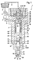
- Fig. 1 is a trained as a common rail injector fuel injector 1 for injecting fuel into a combustion chamber, not shown, also shown an internal combustion engine of a motor vehicle.
- a high pressure pump 2 delivers fuel from a reservoir 3 in a high-pressure fuel storage 4 (Rail). In this fuel, especially diesel or gasoline, under high pressure, stored in this embodiment about 2000bar.
- the fuel injector 1 is connected via other, not shown, fuel injectors via a supply line 5.
- the supply line 5 opens into an annular space 6 radially between a valve body 7 and an injector body 8 (housing part).
- the high-pressure fuel can flow essentially unthrottled in the axial direction in the plane of the drawing down into a pressure space 11 acting as a mini-rail for pressure oscillation minimization.
- the fuel flows directly through axial passages 13 into a nozzle chamber 14 (annular space) also belonging to the injector volume 12 and out of this through at least one injection hole 15 into the combustion chamber of the internal combustion engine.
- the fuel injector 1 is connected via an injector return port 16 to a return line 17. About the return line 17 can be explained later on a control amount of fuel from the fuel injector 1 to the reservoir 3 drain and be fed from there from the high pressure circuit again.
- a two-part injection valve element 18 in this exemplary embodiment is arranged to be adjustable in the axial direction.
- the injection valve element 18 projects with its lower, designed as a nozzle needle first part 19 in a stepped bore 20 of a nozzle body 21 into it.
- the first part 19 is guided axially displaceably with a guide portion 22.
- the axial channels 13 are formed by bevels 9 in the guide section 22 radially between the first part 19 and the nozzle body 21.
- the nozzle body 21 is screwed by means of a union nut, not shown, with the injector body 8.
- the first part 19 (nozzle needle) of the injection valve element 18 is guided in an end blind bore 23 of a second part 24 (control rod) of the injection valve element 18.
- the injection valve element 18 has a closing surface 26 (sealing surface) on a (lower) tip 25 formed on the first part 19, with which the injection valve element 18 can be brought into tight contact with an injection valve element seat 27 formed inside the nozzle body 21.
- the injection valve element 18 abuts against its injection valve element seat 27, ie is in a closed position, the fuel outlet from the at least one injection hole 15 is blocked. If, on the other hand, it is lifted off its injection valve element seat 27, fuel can flow from the pressure chamber 11 via the axial channels 13 and the annular chamber 14 to the injection valve element seat 27 to the injection hole 15 where it is injected substantially under high pressure (rail pressure) into the combustion chamber become.
- a control chamber 29 is limited, which extends over a radially extending in the sleeve-shaped portion of the valve body 7 inlet throttle 30 with high-pressure fuel from the Annulus 6 is supplied.
- the sleeve-shaped portion with control chamber 29 enclosed therein is enclosed radially on the outside with high-pressure fuel, so that an annular Guide gap 31 radially between the sleeve-shaped portion of the valve body 7 and the injection valve element 18, here the second part 24, is comparatively fuel-tight.
- the control chamber 29 is connected via a, extending perpendicularly in the valve body 7 axial channel 32 with outlet throttle 33 with a valve chamber 34 which radially outwardly of an axially adjustable, sleeve-shaped control valve element 35 of a pressure-balanced in the axial direction in the closed state control valve 36 (servo valve) is limited.
- fuel can flow into a low-pressure region 37 of the fuel injector 1 and thence to the injector return port 16 when the sleeve-shaped control valve element 35 is lifted from its control valve element seat 38 formed on the valve body 7, i. when the control valve 36 is open.
- an electromagnetic actuator 39 is provided with an electromagnet 40 which cooperates with an integrally formed with the control valve element 35 anchor plate 41 and subsequently with the sleeve-shaped control valve element 35.
- the electromagnetic actuator 39 raises the control valve element 35 from its formed on the valve body 7, designed in this embodiment as a flat seat control valve element seat 38 from.
- the flow cross-sections of the inlet throttle 30 and the outlet throttle 33 are matched to one another such that when open control valve 36, a net outflow of fuel (control amount) from the control chamber 29 in the low pressure region 37 of the fuel injector 1 and from there via the Injektor Weglaufan gleich 16 and Return line 17 results in the reservoir 3.
- the pressure in the control chamber 29 decreases rapidly, whereby the injection valve element 18, more precisely the first part 19, lifts off from its injection valve element seat 27 so that fuel can flow out of the injector volume 12 through the injection hole 15 into the combustion chamber.
- the energization of the electromagnetic actuator 39 is interrupted, whereby the sleeve-shaped control valve element 35 is adjusted by means of a control spring 42 which is supported on the armature plate 41 in the drawing plane down on its control valve element seat 38.
- the fuel flowing in through the inlet throttle 30 into the control chamber 29 provides for a rapid pressure increase in the control chamber 29 and thus for a force acting on the injection valve element 18 closing force.
- the resulting closing movement of the injection valve element 18 is assisted by a closing spring 43, which is supported at one end on a circumferential collar 44 of the second part 24 and at the other end on a lower, annular end side 45 of the valve body 7.
- a loose pressure pin 47 is accommodated, which is designed as a separate component from the valve body 7.
- the purpose of the cylindrical pressure pin 47 is to seal the valve chamber 34 in the axial direction in order to prevent fuel from the control chamber 29 being able to flow into the low-pressure region 37 when the control valve element 35 is closed, except for an unavoidable amount of leakage.
- the pressure pin 47 also serves to guide the control valve element 35 at its inner periphery formed by the bore 46.
- Fig. 1 results, it is in the fuel injector 1 to a so-called leak-free injector, which has no leakage except for a leak in the region of the control valve 36, since no permanent, acting on the injection valve element 18 in the closing direction low pressure stage is provided.
- the first part 19 is guided into the second part 24 of the injection valve element 18 and guided on the inner circumference of the blind hole 23.
- a hydraulic coupler volume 50 is formed, which couples the movement of the parts 19, 24. How to get out Fig. 1 results, the coupler volume 50 is hydraulically connected to the Injektorvolumen 12 via a consisting of a single throttle bore 51 throttle assembly 52.
- the pressure in the coupler volume 50 drops rapidly and the opening force is transmitted to the first part 19 due to the suction effect in the sequence of its injection valve element seat 27 lifts. Due to the aforementioned negative pressure in the coupler volume 50, this increases because fuel from the injector 12 via the throttle assembly 52 in a range between axially the end face 48 of the first part 19 and the bottom 49 of the blind hole 23 flows.
- the throttle arrangement 52 is designed such that the filling or the increase of the coupler volume 50 does not lead to any functionally relevant change in the maximum stroke of the injection valve element 18. This can also be realized in the case of a multiple injection.
- the fit between the first part 19 and the inner circumference of the blind hole 23 is dimensioned so that the volume flow occurring here compared to the flow volume flow through the throttle assembly 52 is negligible - so the guide gap 53 is to be described as substantially hydraulic tight.
- Fig. 1 is the first part 19 formed in the region of the guide gap 53 and thus formed as a pivot joint, so as to be able to compensate for angular errors and inclinations between the nozzle-side guide and the guide of the injection valve element 18 in the valve body 7.
- FIG. 2 shown embodiment of a fuel injector 1 substantially corresponds to the embodiment according to Fig. 1 , so as to avoid repetition in terms of similarities to the preceding description of the figures as well as on Fig. 1 is referenced. In the following, only differences to the preceding embodiment are explained essentially.
- a throttle bore for connecting the coupler volume 50 to the injector volume 12 has been dispensed with.
- the coupler volume 50 is also formed between the bottom 49 of the blind bore 23 and the upper side 48 in the plane of the drawing of the first part 19 of the injection valve element 18.
- the throttle arrangement 52 is realized in the region of a guide 54 between the outer circumference of the first part 19 and the inner circumference of the blind bore 23.
- the throttle arrangement 52 comprises in the exemplary embodiment shown a number of throttles 55 arranged one behind the other in the axial direction.
- the throttles 55 are each formed between an annular web 56 with a radially tapered outer edge and the inner circumference of the blind bore 23.
- the axial extent of the webs 56 in a voltage applied to the inner circumference of the blind hole 23 area is so short that can form a turbulent flow, with the result that the flow rate through the throttle assembly 52 only disproportionately increases with increasing pressure difference between the coupler volume 50 and 12 injector.
- the two adjacent in the axial direction, annular webs 56 define between them a groove 57 (circumferential groove) on the outer periphery of the first part 19.
- a groove 57 (circumferential groove) on the outer periphery of the first part 19.
- the first part 19 in the region of the guide 54 formed somewhat spherical, so that the first part 19 is pivotable relative to the second part 24 within certain limits, so that angle errors can be compensated.
Landscapes
- Engineering & Computer Science (AREA)
- Chemical & Material Sciences (AREA)
- Combustion & Propulsion (AREA)
- Mechanical Engineering (AREA)
- General Engineering & Computer Science (AREA)
- Physics & Mathematics (AREA)
- Fluid Mechanics (AREA)
- Fuel-Injection Apparatus (AREA)
Claims (10)
- Injecteur de carburant, en particulier injecteur à rampe commune, pour l'injection de carburant dans une chambre de combustion d'un moteur à combustion interne, comprenant un élément de soupape d'injection en plusieurs parties (18), réglable entre une position de fermeture et une position d'ouverture, comprenant une première partie et au moins une deuxième partie (24) déplaçable par rapport à la première partie (19), qui sont accouplées l'une à l'autre par le biais d'un volume de couplage hydraulique (50),
caractérisé en ce que
la première partie (19) est guidée dans la deuxième partie (24) ou la deuxième partie (24) est guidée dans la première partie (19), et en ce que le volume de couplage (50) est connecté à un volume d'injecteur (12) par le biais d'au moins un agencement d'étranglement (52) qui est réalisé de telle sorte que le débit volumique de passage augmente seulement de manière sous-proportionnelle avec l'augmentation de la différence de pression entre le volume d'accouplement (50) et le volume d'injecteur (12). - Injecteur de carburant selon la revendication 1, caractérisé en ce que
l'agencement d'étranglement (52) comprend au moins un, de préférence exclusivement un, alésage d'étranglement (51), en particulier pratiqué dans la première ou la deuxième partie (19, 24). - Injecteur de carburant selon l'une quelconque des revendications 1 ou 2,
caractérisé en ce que
l'agencement d'étranglement (52) présente au moins un étage d'étranglement, notamment à arête vive hydraulique, avec une faible étendue longitudinale dans la direction d'écoulement, qui est dimensionné de préférence de telle sorte qu'il se forme un écoulement turbulent. - Injecteur de carburant selon l'une quelconque des revendications précédentes,
caractérisé en ce que
l'agencement d'étranglement (52) comprend plusieurs étranglements (55) disposés hydrauliquement en rangée. - Injecteur de carburant selon la revendication 4,
caractérisé en ce que
les étranglements (55) sont réalisés radialement entre la première et la deuxième partie (19, 24). - Injecteur de carburant selon la revendication 5,
caractérisé en ce que
l'agencement d'étranglement (52) comprend plusieurs gorges (57) disposées axialement les unes derrière les autres, pratiquées dans la première ou dans la deuxième partie (19, 24). - Injecteur de carburant selon l'une quelconque des revendications précédentes,
caractérisé en ce que
la deuxième partie (24) est un piston de commande limitant une chambre de commande (29) et la première partie (19) est une aiguille de buse coopérant avec un siège d'aiguille de buse. - Injecteur de carburant selon la revendication 7,
caractérisé en ce que
le guide (54) est réalisé sous forme d'articulation pivotante fournissant une possibilité de déplacement relatif de la première et de la deuxième partie (19, 24) par rapport à l'axe médian longitudinal de l'élément de soupape d'injection (18). - Injecteur de carburant selon la revendication 8,
caractérisé en ce que
la première ou la deuxième partie (19, 24) est formée sous forme bombée dans la région du guide (54). - Injecteur de carburant selon l'une quelconque des revendications précédentes,
caractérisé en ce que
l'injecteur de carburant (1) ne présente pas d'étage de basse pression durable.
Applications Claiming Priority (1)
| Application Number | Priority Date | Filing Date | Title |
|---|---|---|---|
| DE102009000181A DE102009000181A1 (de) | 2009-01-13 | 2009-01-13 | Kraftstoff-Injektor |
Publications (3)
| Publication Number | Publication Date |
|---|---|
| EP2206912A2 EP2206912A2 (fr) | 2010-07-14 |
| EP2206912A3 EP2206912A3 (fr) | 2010-07-21 |
| EP2206912B1 true EP2206912B1 (fr) | 2011-08-03 |
Family
ID=42124568
Family Applications (1)
| Application Number | Title | Priority Date | Filing Date |
|---|---|---|---|
| EP09169850A Not-in-force EP2206912B1 (fr) | 2009-01-13 | 2009-09-09 | Injecteur de carburant |
Country Status (4)
| Country | Link |
|---|---|
| US (1) | US8302888B2 (fr) |
| EP (1) | EP2206912B1 (fr) |
| AT (1) | ATE519031T1 (fr) |
| DE (1) | DE102009000181A1 (fr) |
Families Citing this family (8)
| Publication number | Priority date | Publication date | Assignee | Title |
|---|---|---|---|---|
| DE102011015753A1 (de) * | 2011-03-31 | 2012-10-04 | Raphael Füchslin | Einspritzventil |
| DE102012220657A1 (de) | 2012-11-13 | 2014-05-15 | Robert Bosch Gmbh | Brennstoffeinspritzventil |
| JP6145652B2 (ja) * | 2014-01-06 | 2017-06-14 | 株式会社Soken | 燃料噴射弁 |
| GB201412086D0 (en) * | 2014-07-08 | 2014-08-20 | Delphi International Operations Luxembourg S.�.R.L. | Fuel injector for an internal combustion engine |
| DE102014215749A1 (de) * | 2014-08-08 | 2016-02-11 | Continental Automotive Gmbh | Drosseleinrichtung zum Steuern einer einer Kraftstoff-Einspritzdüse zuzuführenden Kraftstoffmenge sowie Einspritzeinrichtung |
| CN104533683B (zh) * | 2014-11-26 | 2017-01-25 | 中国北方发动机研究所(天津) | 一种高压共轨喷油器滑阀结构 |
| US11506162B2 (en) * | 2020-11-17 | 2022-11-22 | Caterpillar Inc. | Trapped volume split check assembly in fuel injector |
| DE102021200154A1 (de) * | 2021-01-11 | 2022-07-14 | Robert Bosch Gesellschaft mit beschränkter Haftung | Kraftstoffeinspritzvorrichtung |
Family Cites Families (12)
| Publication number | Priority date | Publication date | Assignee | Title |
|---|---|---|---|---|
| IT232490Y1 (it) * | 1994-07-01 | 2000-01-10 | Elasis Sistema Ricerca Fiat | Dispositivo di registrazione della corsa dell'otturatore per un iniettore di combustibile |
| ATE226279T1 (de) * | 1998-03-26 | 2002-11-15 | Mtu Friedrichshafen Gmbh | Hochdruck-kolbenzylindereinheit |
| DE10104618A1 (de) * | 2001-02-02 | 2002-08-08 | Bosch Gmbh Robert | Ventil zum Steuern von Flüssigkeiten |
| DE50214476D1 (de) * | 2001-07-03 | 2010-07-15 | Crt Common Rail Tech Ag | Brennstoffeinspritzventil für Verbrennungskraftmaschinen |
| DE102004024527A1 (de) * | 2004-05-18 | 2005-12-15 | Robert Bosch Gmbh | Kraftstoffeinspritzeinrichtung |
| DE102005026514B4 (de) * | 2005-02-18 | 2008-12-24 | Robert Bosch Gmbh | Einspritzdüse |
| DE102005059169A1 (de) * | 2005-12-12 | 2007-06-14 | Robert Bosch Gmbh | Kraftstoffinjektor mit direkt betätigbarem Einspritzventilglied |
| RU2438035C2 (ru) * | 2006-03-03 | 2011-12-27 | Ганзер-Хюдромаг Аг | Инжекторный клапан для топлива для двигателя внутреннего сгорания (варианты) |
| DE102006036780A1 (de) * | 2006-08-07 | 2008-02-21 | Robert Bosch Gmbh | Krafstoffinjektor mit direkter Nadelsteuerung und Servoventil-Unterstützung |
| DE102007014359A1 (de) * | 2006-09-01 | 2008-03-06 | Robert Bosch Gmbh | Injektor für eine Kraftstoffeinspritzanlage |
| DE102007001363A1 (de) * | 2007-01-09 | 2008-07-10 | Robert Bosch Gmbh | Injektor zum Einspritzen von Kraftstoff in Brennräume von Brennkraftmaschinen |
| DE102008040680A1 (de) * | 2008-07-24 | 2010-01-28 | Robert Bosch Gmbh | Kraftstoff-Injektor |
-
2009
- 2009-01-13 DE DE102009000181A patent/DE102009000181A1/de not_active Withdrawn
- 2009-09-09 AT AT09169850T patent/ATE519031T1/de active
- 2009-09-09 EP EP09169850A patent/EP2206912B1/fr not_active Not-in-force
-
2010
- 2010-01-13 US US12/686,606 patent/US8302888B2/en not_active Expired - Fee Related
Also Published As
| Publication number | Publication date |
|---|---|
| DE102009000181A1 (de) | 2010-07-15 |
| EP2206912A2 (fr) | 2010-07-14 |
| US20100175665A1 (en) | 2010-07-15 |
| ATE519031T1 (de) | 2011-08-15 |
| EP2206912A3 (fr) | 2010-07-21 |
| US8302888B2 (en) | 2012-11-06 |
Similar Documents
| Publication | Publication Date | Title |
|---|---|---|
| EP2171255B1 (fr) | Étranglement au niveau du pointeau d'une soupape d'injection de carburant pour moteurs à combustion interne | |
| EP2206912B1 (fr) | Injecteur de carburant | |
| EP2108080B1 (fr) | Injecteur pour injecter du carburant dans les chambres de combustion des moteurs à combustion interne | |
| EP3535486B1 (fr) | Soupape d'injection de carburant pour injecter un carburant gazeux et / ou liquide | |
| EP2387661B1 (fr) | Injecteur de carburant pour moteurs à combustion interne | |
| WO2012123130A1 (fr) | Dispositif formant soupape permettant de coupler ou de distribuer un fluide | |
| EP2310662B1 (fr) | Injecteur de carburant | |
| DE10100390A1 (de) | Einspritzventil | |
| EP2294309A1 (fr) | Injecteur de carburant | |
| WO2009141182A1 (fr) | Injecteur de carburant | |
| EP1910663B1 (fr) | Systeme d'injection de carburant pour moteur a combustion interne a injection directe de carburant | |
| EP1541859B1 (fr) | Injecteur | |
| EP1671028A1 (fr) | Soupape pour commander une liaison dans un systeme de liquide haute pression, notamment un dispositif d'injection de carburant pour un moteur a combustion interne | |
| EP2022975B1 (fr) | Injecteur | |
| EP3380715B1 (fr) | Injecteur de carburant | |
| EP2019198B1 (fr) | Injecteur | |
| EP1574701A1 (fr) | Injecteur de common rail | |
| WO2002061266A2 (fr) | Soupape de regulation de liquides | |
| WO2009135712A1 (fr) | Injecteur de carburant et procédé de production associé | |
| DE102007001365A1 (de) | Injektor mit Steuer- und Schaltkammer | |
| DE102008041561A1 (de) | Kraftstoffinjektor sowie Auslegungsverfahren für einen Kraftstoffinjektor | |
| EP2439398A1 (fr) | Soupape d'injection de combustible | |
| WO2016058969A1 (fr) | Soupape d'injection servant à injecter un fluide dans la chambre de combustion d'un moteur a combustion interne | |
| WO2003040544A1 (fr) | Module de commande destine a un injecteur d'un systeme d'injection de reservoir | |
| EP2035685A1 (fr) | Dispositif d'injection de carburant pour moteur à combustion interne |
Legal Events
| Date | Code | Title | Description |
|---|---|---|---|
| PUAI | Public reference made under article 153(3) epc to a published international application that has entered the european phase |
Free format text: ORIGINAL CODE: 0009012 |
|
| PUAL | Search report despatched |
Free format text: ORIGINAL CODE: 0009013 |
|
| AK | Designated contracting states |
Kind code of ref document: A2 Designated state(s): AT BE BG CH CY CZ DE DK EE ES FI FR GB GR HR HU IE IS IT LI LT LU LV MC MK MT NL NO PL PT RO SE SI SK SM TR |
|
| AX | Request for extension of the european patent |
Extension state: AL BA RS |
|
| AK | Designated contracting states |
Kind code of ref document: A3 Designated state(s): AT BE BG CH CY CZ DE DK EE ES FI FR GB GR HR HU IE IS IT LI LT LU LV MC MK MT NL NO PL PT RO SE SI SK SM TR |
|
| AX | Request for extension of the european patent |
Extension state: AL BA RS |
|
| RIC1 | Information provided on ipc code assigned before grant |
Ipc: F02M 61/16 20060101ALI20100614BHEP Ipc: F02M 61/12 20060101ALI20100614BHEP Ipc: F02M 47/02 20060101AFI20100511BHEP |
|
| 17P | Request for examination filed |
Effective date: 20110121 |
|
| GRAP | Despatch of communication of intention to grant a patent |
Free format text: ORIGINAL CODE: EPIDOSNIGR1 |
|
| RIC1 | Information provided on ipc code assigned before grant |
Ipc: F02M 61/12 20060101ALI20110303BHEP Ipc: F02M 47/02 20060101AFI20110303BHEP Ipc: F02M 61/16 20060101ALI20110303BHEP |
|
| GRAS | Grant fee paid |
Free format text: ORIGINAL CODE: EPIDOSNIGR3 |
|
| GRAA | (expected) grant |
Free format text: ORIGINAL CODE: 0009210 |
|
| AK | Designated contracting states |
Kind code of ref document: B1 Designated state(s): AT BE BG CH CY CZ DE DK EE ES FI FR GB GR HR HU IE IS IT LI LT LU LV MC MK MT NL NO PL PT RO SE SI SK SM TR |
|
| REG | Reference to a national code |
Ref country code: GB Ref legal event code: FG4D Free format text: NOT ENGLISH |
|
| REG | Reference to a national code |
Ref country code: CH Ref legal event code: EP |
|
| REG | Reference to a national code |
Ref country code: IE Ref legal event code: FG4D Free format text: LANGUAGE OF EP DOCUMENT: GERMAN |
|
| REG | Reference to a national code |
Ref country code: DE Ref legal event code: R096 Ref document number: 502009001034 Country of ref document: DE Effective date: 20110929 |
|
| REG | Reference to a national code |
Ref country code: NL Ref legal event code: VDEP Effective date: 20110803 |
|
| LTIE | Lt: invalidation of european patent or patent extension |
Effective date: 20110803 |
|
| PG25 | Lapsed in a contracting state [announced via postgrant information from national office to epo] |
Ref country code: PT Free format text: LAPSE BECAUSE OF FAILURE TO SUBMIT A TRANSLATION OF THE DESCRIPTION OR TO PAY THE FEE WITHIN THE PRESCRIBED TIME-LIMIT Effective date: 20111205 Ref country code: SE Free format text: LAPSE BECAUSE OF FAILURE TO SUBMIT A TRANSLATION OF THE DESCRIPTION OR TO PAY THE FEE WITHIN THE PRESCRIBED TIME-LIMIT Effective date: 20110803 Ref country code: LT Free format text: LAPSE BECAUSE OF FAILURE TO SUBMIT A TRANSLATION OF THE DESCRIPTION OR TO PAY THE FEE WITHIN THE PRESCRIBED TIME-LIMIT Effective date: 20110803 Ref country code: HR Free format text: LAPSE BECAUSE OF FAILURE TO SUBMIT A TRANSLATION OF THE DESCRIPTION OR TO PAY THE FEE WITHIN THE PRESCRIBED TIME-LIMIT Effective date: 20110803 Ref country code: FI Free format text: LAPSE BECAUSE OF FAILURE TO SUBMIT A TRANSLATION OF THE DESCRIPTION OR TO PAY THE FEE WITHIN THE PRESCRIBED TIME-LIMIT Effective date: 20110803 Ref country code: IS Free format text: LAPSE BECAUSE OF FAILURE TO SUBMIT A TRANSLATION OF THE DESCRIPTION OR TO PAY THE FEE WITHIN THE PRESCRIBED TIME-LIMIT Effective date: 20111203 Ref country code: NL Free format text: LAPSE BECAUSE OF FAILURE TO SUBMIT A TRANSLATION OF THE DESCRIPTION OR TO PAY THE FEE WITHIN THE PRESCRIBED TIME-LIMIT Effective date: 20110803 Ref country code: NO Free format text: LAPSE BECAUSE OF FAILURE TO SUBMIT A TRANSLATION OF THE DESCRIPTION OR TO PAY THE FEE WITHIN THE PRESCRIBED TIME-LIMIT Effective date: 20111103 |
|
| PG25 | Lapsed in a contracting state [announced via postgrant information from national office to epo] |
Ref country code: LV Free format text: LAPSE BECAUSE OF FAILURE TO SUBMIT A TRANSLATION OF THE DESCRIPTION OR TO PAY THE FEE WITHIN THE PRESCRIBED TIME-LIMIT Effective date: 20110803 Ref country code: PL Free format text: LAPSE BECAUSE OF FAILURE TO SUBMIT A TRANSLATION OF THE DESCRIPTION OR TO PAY THE FEE WITHIN THE PRESCRIBED TIME-LIMIT Effective date: 20110803 Ref country code: GR Free format text: LAPSE BECAUSE OF FAILURE TO SUBMIT A TRANSLATION OF THE DESCRIPTION OR TO PAY THE FEE WITHIN THE PRESCRIBED TIME-LIMIT Effective date: 20111104 Ref country code: CY Free format text: LAPSE BECAUSE OF FAILURE TO SUBMIT A TRANSLATION OF THE DESCRIPTION OR TO PAY THE FEE WITHIN THE PRESCRIBED TIME-LIMIT Effective date: 20110803 Ref country code: SI Free format text: LAPSE BECAUSE OF FAILURE TO SUBMIT A TRANSLATION OF THE DESCRIPTION OR TO PAY THE FEE WITHIN THE PRESCRIBED TIME-LIMIT Effective date: 20110803 |
|
| REG | Reference to a national code |
Ref country code: IE Ref legal event code: FD4D |
|
| BERE | Be: lapsed |
Owner name: ROBERT BOSCH G.M.B.H. Effective date: 20110930 |
|
| PG25 | Lapsed in a contracting state [announced via postgrant information from national office to epo] |
Ref country code: MC Free format text: LAPSE BECAUSE OF NON-PAYMENT OF DUE FEES Effective date: 20110930 Ref country code: CZ Free format text: LAPSE BECAUSE OF FAILURE TO SUBMIT A TRANSLATION OF THE DESCRIPTION OR TO PAY THE FEE WITHIN THE PRESCRIBED TIME-LIMIT Effective date: 20110803 Ref country code: SK Free format text: LAPSE BECAUSE OF FAILURE TO SUBMIT A TRANSLATION OF THE DESCRIPTION OR TO PAY THE FEE WITHIN THE PRESCRIBED TIME-LIMIT Effective date: 20110803 Ref country code: IE Free format text: LAPSE BECAUSE OF FAILURE TO SUBMIT A TRANSLATION OF THE DESCRIPTION OR TO PAY THE FEE WITHIN THE PRESCRIBED TIME-LIMIT Effective date: 20110803 |
|
| PG25 | Lapsed in a contracting state [announced via postgrant information from national office to epo] |
Ref country code: RO Free format text: LAPSE BECAUSE OF FAILURE TO SUBMIT A TRANSLATION OF THE DESCRIPTION OR TO PAY THE FEE WITHIN THE PRESCRIBED TIME-LIMIT Effective date: 20110803 Ref country code: EE Free format text: LAPSE BECAUSE OF FAILURE TO SUBMIT A TRANSLATION OF THE DESCRIPTION OR TO PAY THE FEE WITHIN THE PRESCRIBED TIME-LIMIT Effective date: 20110803 |
|
| PLBE | No opposition filed within time limit |
Free format text: ORIGINAL CODE: 0009261 |
|
| STAA | Information on the status of an ep patent application or granted ep patent |
Free format text: STATUS: NO OPPOSITION FILED WITHIN TIME LIMIT |
|
| PG25 | Lapsed in a contracting state [announced via postgrant information from national office to epo] |
Ref country code: DK Free format text: LAPSE BECAUSE OF FAILURE TO SUBMIT A TRANSLATION OF THE DESCRIPTION OR TO PAY THE FEE WITHIN THE PRESCRIBED TIME-LIMIT Effective date: 20110803 Ref country code: BE Free format text: LAPSE BECAUSE OF NON-PAYMENT OF DUE FEES Effective date: 20110930 |
|
| 26N | No opposition filed |
Effective date: 20120504 |
|
| REG | Reference to a national code |
Ref country code: DE Ref legal event code: R097 Ref document number: 502009001034 Country of ref document: DE Effective date: 20120504 |
|
| PG25 | Lapsed in a contracting state [announced via postgrant information from national office to epo] |
Ref country code: MK Free format text: LAPSE BECAUSE OF FAILURE TO SUBMIT A TRANSLATION OF THE DESCRIPTION OR TO PAY THE FEE WITHIN THE PRESCRIBED TIME-LIMIT Effective date: 20110803 Ref country code: MT Free format text: LAPSE BECAUSE OF FAILURE TO SUBMIT A TRANSLATION OF THE DESCRIPTION OR TO PAY THE FEE WITHIN THE PRESCRIBED TIME-LIMIT Effective date: 20110803 |
|
| PG25 | Lapsed in a contracting state [announced via postgrant information from national office to epo] |
Ref country code: ES Free format text: LAPSE BECAUSE OF FAILURE TO SUBMIT A TRANSLATION OF THE DESCRIPTION OR TO PAY THE FEE WITHIN THE PRESCRIBED TIME-LIMIT Effective date: 20111114 Ref country code: SM Free format text: LAPSE BECAUSE OF FAILURE TO SUBMIT A TRANSLATION OF THE DESCRIPTION OR TO PAY THE FEE WITHIN THE PRESCRIBED TIME-LIMIT Effective date: 20110803 |
|
| PG25 | Lapsed in a contracting state [announced via postgrant information from national office to epo] |
Ref country code: LU Free format text: LAPSE BECAUSE OF NON-PAYMENT OF DUE FEES Effective date: 20110909 |
|
| PG25 | Lapsed in a contracting state [announced via postgrant information from national office to epo] |
Ref country code: BG Free format text: LAPSE BECAUSE OF FAILURE TO SUBMIT A TRANSLATION OF THE DESCRIPTION OR TO PAY THE FEE WITHIN THE PRESCRIBED TIME-LIMIT Effective date: 20111103 |
|
| PG25 | Lapsed in a contracting state [announced via postgrant information from national office to epo] |
Ref country code: TR Free format text: LAPSE BECAUSE OF FAILURE TO SUBMIT A TRANSLATION OF THE DESCRIPTION OR TO PAY THE FEE WITHIN THE PRESCRIBED TIME-LIMIT Effective date: 20110803 |
|
| PG25 | Lapsed in a contracting state [announced via postgrant information from national office to epo] |
Ref country code: HU Free format text: LAPSE BECAUSE OF FAILURE TO SUBMIT A TRANSLATION OF THE DESCRIPTION OR TO PAY THE FEE WITHIN THE PRESCRIBED TIME-LIMIT Effective date: 20110803 |
|
| REG | Reference to a national code |
Ref country code: CH Ref legal event code: PL |
|
| GBPC | Gb: european patent ceased through non-payment of renewal fee |
Effective date: 20130909 |
|
| PG25 | Lapsed in a contracting state [announced via postgrant information from national office to epo] |
Ref country code: CH Free format text: LAPSE BECAUSE OF NON-PAYMENT OF DUE FEES Effective date: 20130930 Ref country code: GB Free format text: LAPSE BECAUSE OF NON-PAYMENT OF DUE FEES Effective date: 20130909 Ref country code: LI Free format text: LAPSE BECAUSE OF NON-PAYMENT OF DUE FEES Effective date: 20130930 |
|
| REG | Reference to a national code |
Ref country code: AT Ref legal event code: MM01 Ref document number: 519031 Country of ref document: AT Kind code of ref document: T Effective date: 20140909 |
|
| PG25 | Lapsed in a contracting state [announced via postgrant information from national office to epo] |
Ref country code: AT Free format text: LAPSE BECAUSE OF NON-PAYMENT OF DUE FEES Effective date: 20140909 |
|
| REG | Reference to a national code |
Ref country code: FR Ref legal event code: PLFP Year of fee payment: 8 |
|
| REG | Reference to a national code |
Ref country code: FR Ref legal event code: PLFP Year of fee payment: 9 |
|
| REG | Reference to a national code |
Ref country code: FR Ref legal event code: PLFP Year of fee payment: 10 |
|
| PGFP | Annual fee paid to national office [announced via postgrant information from national office to epo] |
Ref country code: IT Payment date: 20190920 Year of fee payment: 11 Ref country code: FR Payment date: 20190923 Year of fee payment: 11 |
|
| PGFP | Annual fee paid to national office [announced via postgrant information from national office to epo] |
Ref country code: DE Payment date: 20191125 Year of fee payment: 11 |
|
| REG | Reference to a national code |
Ref country code: DE Ref legal event code: R119 Ref document number: 502009001034 Country of ref document: DE |
|
| PG25 | Lapsed in a contracting state [announced via postgrant information from national office to epo] |
Ref country code: FR Free format text: LAPSE BECAUSE OF NON-PAYMENT OF DUE FEES Effective date: 20200930 Ref country code: DE Free format text: LAPSE BECAUSE OF NON-PAYMENT OF DUE FEES Effective date: 20210401 |
|
| PG25 | Lapsed in a contracting state [announced via postgrant information from national office to epo] |
Ref country code: IT Free format text: LAPSE BECAUSE OF NON-PAYMENT OF DUE FEES Effective date: 20200909 |