EP3535486B1 - Soupape d'injection de carburant pour injecter un carburant gazeux et / ou liquide - Google Patents
Soupape d'injection de carburant pour injecter un carburant gazeux et / ou liquide Download PDFInfo
- Publication number
- EP3535486B1 EP3535486B1 EP17780079.4A EP17780079A EP3535486B1 EP 3535486 B1 EP3535486 B1 EP 3535486B1 EP 17780079 A EP17780079 A EP 17780079A EP 3535486 B1 EP3535486 B1 EP 3535486B1
- Authority
- EP
- European Patent Office
- Prior art keywords
- valve
- control
- valve member
- fuel injection
- way
- Prior art date
- Legal status (The legal status is an assumption and is not a legal conclusion. Google has not performed a legal analysis and makes no representation as to the accuracy of the status listed.)
- Active
Links
Images


Classifications
-
- F—MECHANICAL ENGINEERING; LIGHTING; HEATING; WEAPONS; BLASTING
- F02—COMBUSTION ENGINES; HOT-GAS OR COMBUSTION-PRODUCT ENGINE PLANTS
- F02M—SUPPLYING COMBUSTION ENGINES IN GENERAL WITH COMBUSTIBLE MIXTURES OR CONSTITUENTS THEREOF
- F02M21/00—Apparatus for supplying engines with non-liquid fuels, e.g. gaseous fuels stored in liquid form
- F02M21/02—Apparatus for supplying engines with non-liquid fuels, e.g. gaseous fuels stored in liquid form for gaseous fuels
- F02M21/0218—Details on the gaseous fuel supply system, e.g. tanks, valves, pipes, pumps, rails, injectors or mixers
- F02M21/0248—Injectors
-
- F—MECHANICAL ENGINEERING; LIGHTING; HEATING; WEAPONS; BLASTING
- F02—COMBUSTION ENGINES; HOT-GAS OR COMBUSTION-PRODUCT ENGINE PLANTS
- F02D—CONTROLLING COMBUSTION ENGINES
- F02D19/00—Controlling engines characterised by their use of non-liquid fuels, pluralities of fuels, or non-fuel substances added to the combustible mixtures
- F02D19/06—Controlling engines characterised by their use of non-liquid fuels, pluralities of fuels, or non-fuel substances added to the combustible mixtures peculiar to engines working with pluralities of fuels, e.g. alternatively with light and heavy fuel oil, other than engines indifferent to the fuel consumed
-
- F—MECHANICAL ENGINEERING; LIGHTING; HEATING; WEAPONS; BLASTING
- F02—COMBUSTION ENGINES; HOT-GAS OR COMBUSTION-PRODUCT ENGINE PLANTS
- F02M—SUPPLYING COMBUSTION ENGINES IN GENERAL WITH COMBUSTIBLE MIXTURES OR CONSTITUENTS THEREOF
- F02M2200/00—Details of fuel-injection apparatus, not otherwise provided for
- F02M2200/46—Valves, e.g. injectors, with concentric valve bodies
-
- F—MECHANICAL ENGINEERING; LIGHTING; HEATING; WEAPONS; BLASTING
- F02—COMBUSTION ENGINES; HOT-GAS OR COMBUSTION-PRODUCT ENGINE PLANTS
- F02M—SUPPLYING COMBUSTION ENGINES IN GENERAL WITH COMBUSTIBLE MIXTURES OR CONSTITUENTS THEREOF
- F02M43/00—Fuel-injection apparatus operating simultaneously on two or more fuels, or on a liquid fuel and another liquid, e.g. the other liquid being an anti-knock additive
- F02M43/04—Injectors peculiar thereto
-
- F—MECHANICAL ENGINEERING; LIGHTING; HEATING; WEAPONS; BLASTING
- F02—COMBUSTION ENGINES; HOT-GAS OR COMBUSTION-PRODUCT ENGINE PLANTS
- F02M—SUPPLYING COMBUSTION ENGINES IN GENERAL WITH COMBUSTIBLE MIXTURES OR CONSTITUENTS THEREOF
- F02M45/00—Fuel-injection apparatus characterised by having a cyclic delivery of specific time/pressure or time/quantity relationship
- F02M45/02—Fuel-injection apparatus characterised by having a cyclic delivery of specific time/pressure or time/quantity relationship with each cyclic delivery being separated into two or more parts
- F02M45/04—Fuel-injection apparatus characterised by having a cyclic delivery of specific time/pressure or time/quantity relationship with each cyclic delivery being separated into two or more parts with a small initial part, e.g. initial part for partial load and initial and main part for full load
- F02M45/08—Injectors peculiar thereto
- F02M45/086—Having more than one injection-valve controlling discharge orifices
-
- Y—GENERAL TAGGING OF NEW TECHNOLOGICAL DEVELOPMENTS; GENERAL TAGGING OF CROSS-SECTIONAL TECHNOLOGIES SPANNING OVER SEVERAL SECTIONS OF THE IPC; TECHNICAL SUBJECTS COVERED BY FORMER USPC CROSS-REFERENCE ART COLLECTIONS [XRACs] AND DIGESTS
- Y02—TECHNOLOGIES OR APPLICATIONS FOR MITIGATION OR ADAPTATION AGAINST CLIMATE CHANGE
- Y02T—CLIMATE CHANGE MITIGATION TECHNOLOGIES RELATED TO TRANSPORTATION
- Y02T10/00—Road transport of goods or passengers
- Y02T10/10—Internal combustion engine [ICE] based vehicles
- Y02T10/30—Use of alternative fuels, e.g. biofuels
Definitions
- the invention relates to a fuel injector for injecting a gaseous and/or liquid fuel into a combustion chamber of an internal combustion engine.
- fuel injectors are also known as double fuel injectors, two-fuel injectors or dual-fuel injectors.
- Fuel injection valves of the above-mentioned type generally have two nozzle needles that can be lifted into one another and are guided into one another for opening and closing injection openings for the different fuels.
- the control is comparatively complex, since there must be a control valve for each nozzle needle. Furthermore, both control valves must be precisely timed to each other.
- the liquid fuel is allowed to leak into the gas chamber via a leakage gap, so that when the nozzle needle opens, gas flows out of the gas chamber via the injection openings into a combustion chamber, entraining the liquid fuel present within the gas chamber.
- the leakage gap is dimensioned in such a way that by injecting the gaseous fuel, such an amount of liquid fuel gets into the combustion chamber that the ignitability of the mixture is increased to the desired level.
- a further nozzle needle is provided, which is guided in a bore of the first nozzle needle in a lifting manner in order to release and close at least one further injection opening.
- a control valve is provided to control the stroke movements of the two nozzle needles, so that the control of the fuel metering valve is no less complex than with a conventional dual-fuel injector.
- the control valves are used for hydraulic pilot control of the coaxially arranged nozzle needles.
- each nozzle needle is assigned a control chamber which can be relieved via a control valve, so that a control pressure applied to the nozzle needle is reduced and the respective nozzle needle is able to open.
- the amount of spillage occurring during the hydraulic pilot control increases as the stroke of the nozzle needle increases and/or as the diameter of the control chamber increases. This means that it is particularly large on the outer nozzle needle due to the principle involved.
- the spill quantity directly influences the dimensioning of the assigned control valve, whereby the rule applies for the same type of valve: the larger the spill quantity, the larger the control valve is built.
- the available installation space is usually limited. Another example is out EP 1 584 813 known.
- the present invention is therefore based on the object of specifying a fuel injection valve for injecting a gaseous and/or liquid fuel into a combustion chamber of an internal combustion engine, which can be controlled by means of control valves in such a way that the valve requirements, in particular with regard to the arrangement and/or the space requirement of the Control valves, can be kept low even with large amounts spilled.
- the fuel injection valve proposed for injecting a gaseous and/or liquid fuel into a combustion chamber of an internal combustion engine comprises a first valve member accommodated such that it can move in a central bore of a nozzle body and a second valve member accommodated such that it can move in a central bore of the first valve member, as well as control valves for hydraulic pilot control of the two valve members .
- Each valve member is assigned a control chamber that can be relieved via a control valve.
- a further valve which can be controlled hydraulically via the control valve, is arranged at least between a control chamber and a control valve serving to relieve the pressure in the control chamber.
- At least one control chamber can only be relieved indirectly via the control valve assigned to it, since another valve is arranged between the control chamber and the control valve, which must be opened to relieve the control chamber.
- the further valve is opened by means of the control valve. Accordingly, the specific configuration and the position of the additional valve are decisive for the design of the control valve and no longer the volume of the control chamber, which is to be relieved via the additional valve.
- the further valve has the advantage that it can be of comparatively simple design and can be arranged close to the control valve. Accordingly, a comparatively small control valve can be used to control the additional valve.
- the control chamber assigned to the outer valve member also has a larger volume than the control chamber assigned to the inner valve member.
- the additional valve proposed according to the invention therefore preferably serves to relieve the pressure on the control chamber assigned to the outer valve member.
- an additional control chamber which is delimited by an actuating element for actuating a closing element of the additional valve.
- a distance between the control chamber and the control valve can be bridged in a simple manner via the actuating element of the additional valve.
- the distance of the control valve from the control chamber has no effect on the spill quantity, so that the control valve can also be arranged at an axial distance behind the other control valve. This means that, in contrast to the usual parallel arrangement of the two control valves, an arrangement can also be implemented in which the control valves are located one behind the other.
- the actuating element of the further valve is preferably designed in the form of a rod or piston.
- the closing element can in particular be designed as a sphere.
- a spherical recess can be formed in an end face of the actuating element that faces the closing element.
- the further valve is designed as a 2/2-way valve, for example as a ball seat valve, so that the further valve can be implemented particularly easily and also in a space-saving manner.
- control room which corresponds to the first, i. H. is assigned to the outer valve member, is delimited by a throttle plate in which an inlet throttle and an outlet throttle are formed, which are connected to the control chamber.
- the control chamber can be filled with a fluid, preferably with the liquid fuel, via the inlet throttle in order to increase the control pressure in the control chamber.
- the control chamber is relieved via the outlet throttle when the other valve is open.
- the outlet throttle is preferably arranged in an outlet channel which opens into a valve seat for the additional valve.
- the further valve is accordingly only separated from the control chamber by the throttle plate, which enables the further valve to be arranged close to the control chamber.
- control chamber which is assigned to the first or outer valve member, is preferably connected via the inlet throttle and/or an inlet channel to a spring chamber, in which at least one spring for prestressing a valve member in the direction a sealing seat is included.
- the spring chamber can be used as a fluid reservoir for filling the control chamber.
- the liquid fuel is preferably used as the fluid.
- the control chamber which is associated with the second or the inner valve member, is preferably delimited by a sealing sleeve, in which an end section of the second valve member is received such that it can be moved.
- the sealing sleeve seals the control room from the outside.
- the sealing sleeve is preferably arranged in the spring chamber and is axially prestressed by one of the springs accommodated in the spring chamber. The axial preload ensures the sealing effect of the sealing sleeve.
- the sealing sleeve is preferably pressed against a body component of the fuel injector via the spring, so that the body component, the sealing sleeve and the second or inner valve member enclose the control chamber.
- At least one control valve is advantageously designed as a 3/2-way valve. If the 3/2-way valve opens in order to relieve a control chamber assigned to the valve members directly or indirectly via the further valve, the inlet throttle is blocked and the inflow of fluid into the control chamber is interrupted. Since no quantity flows into the control chamber when the control valve is open, the discharge quantity is reduced at the same time. Accordingly, the valve requirements can be further reduced.
- the further valve arranged between a control chamber and a control valve leads to a cascade-like hydraulic pilot control of the valve member assigned to the control chamber.
- the cascade control can achieve excess force that can be used to relieve the control chamber over larger cross sections. This in turn leads to rapid opening and closing behavior of the associated valve member.
- the cascade-type pilot control also allows the control valve to be positioned at a certain distance from the control chamber without significant deficits in the switching dynamics, since the control lines can be kept short.
- control valves can be arranged next to one another or one behind the other.
- the arrangement one behind the other enables new, slim designs and thus improved engine compatibility.
- the axial dimension or the length of the actuating element of the additional valve can be selected in such a way that the distance between the control valve and the control chamber is optimally bridged. As a result, the length of the associated control lines is reduced.
- control valves can each be actuated via an electrical, in particular an electromagnetic or piezoelectric, actuator.
- each control valve is assigned a magnetic actuator or a piezo actuator. In this way, both control valves can be controlled independently of one another.
- the nozzle body is clamped axially to at least one other body component and/or the throttle plate via a nozzle clamping nut.
- the axial tension causes a sealing force that ensures the necessary sealing of the fuel-carrying spaces to the outside.
- the axial preload counteracts internal leakage and thus mixing of the different fuels.
- the fuel injection valve shown for injecting a gaseous and/or liquid fuel into a combustion chamber of an internal combustion engine comprises a nozzle body 2 with a central bore 1 in which a first valve member 3 is accommodated in a lifting manner.
- the first valve member 3 also has a central bore 4 .
- a second valve member 5 is guided in a lifting manner.
- the central bore 4 of the first valve member 3 can be charged with liquid fuel and the central bore 1 of the nozzle body 2 can be charged with gaseous fuel. Accordingly, the gaseous fuel can be introduced into the combustion chamber via a lifting movement of the first valve member 3 , while the liquid fuel is injected via a lifting movement of the second valve member 5 .
- the first valve member 3 interacts with a first sealing seat 23 which is formed by the nozzle body 2 . If the first valve member 3 lifts off the sealing seat 23, it releases injection openings (not shown) through which the gaseous fuel is introduced into the combustion chamber.
- the second valve member 5 interacts with a sealing seat 24 which is formed in the first valve member 3 . If the second valve member 5 lifts off the sealing seat 24, injection openings (not shown) formed in the first valve member 3 are released for injecting the liquid fuel.
- Each valve member 3 , 5 is assigned a control chamber 8 , 9 , each control chamber 8 , 9 being able to be relieved of pressure via its own control valve 6 , 7 .
- the control pressure in the control chamber 8, 9 drops and the respective valve member 3, 5 is able to open against the spring force of a spring 21, 22, by means of which the valve member 3, 5 is axially prestressed against the sealing seat 23, 24.
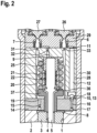
- the springs 21, 22 are housed in a spring chamber 20 formed in a body member 28 (see Fig 2 ).
- the springs 21, 22 are arranged coaxially and surround an end section of the second or inner valve member 5 that protrudes into the spring chamber 20.
- the spring 22 is supported on the one hand directly on an annular collar 36 of the second or inner valve member 5 and on the other hand on a sealing sleeve 25 , which together with the valve member 5 and the body part 28 delimits the control space 9 .
- the additional spring 21 is supported indirectly via a collar sleeve 37 on the first or outer valve member 3 , the collar sleeve 37 being passed through a throttle plate 14 which is arranged between the nozzle body 2 and the body component 28 .
- the throttle plate 14, the nozzle body 2, the first (outer) valve member 3 and the collar sleeve 37 jointly delimit the control chamber 8 acted upon, so that on the valve member 3 weighs a changing control pressure.
- the control valve 6 is opened.
- the control pressure in a control chamber 11 which is in contact with a rod-shaped actuating element 12 of a further valve 10 with a spherical closing element 13 initially falls.
- the closing element 13 interacts with a valve seat 18 which is formed in the throttle plate 14 so that the outflow channel 17 opens into the valve seat 18 .
- the falling control pressure in the control chamber 11 causes the further valve 10 embodied as a ball seat valve to open and release the outflow channel 17 .
- the control chamber 8 is relieved and the first (outer) valve member 3 is able to open against the spring force of the spring 21 in order to blow gaseous fuel into the combustion chamber.
- control valve 6 In order to end the injection of gaseous fuel into the combustion chamber, the control valve 6 is closed again, so that liquid fuel flows into the control chamber 11 via an inlet throttle 33 . As a result, the control pressure in the control chamber 11 increases, as a result of which the actuating element 12 is pressed downwards. The actuating element 12 places the spherical closing element 13 in the valve seat 18. The further valve 10 closes and the control pressure in the control chamber 8 increases. This in turn leads to the closing of the first (outer) valve member 3.
- a pilot quantity of the liquid fuel which is preferably diesel fuel, is injected into the combustion chamber.
- the liquid fuel preheats the combustion chamber and in this way ensures the required ignition temperature of the gaseous fuel.
- the second (inner) valve member 5 are pressed.
- the control valve 7 is opened, which is arranged together with the control valve 6 in a further body component 29 adjoining the body component 28 and braced therewith via a nozzle clamping nut 30 .
- the control valve 7 opens, the control chamber 9 is relieved via an outlet throttle 32 .
- control valve 7 like the control valve 6, is designed as a 3/2-way valve, the inflow of liquid fuel into the control chamber 9 via an inlet throttle 31 is blocked at the same time.
- the control pressure in the control chamber 9 drops and the valve member 5 is able to open against the spring force of the spring 22 . If the injection of liquid fuel is to be ended, the control valve 9 is closed so that the control pressure in the control chamber 9 rises again and the valve member 5 returns to the sealing seat 24 .
- control valve 7 Since the control valve 7 is arranged close to the control chamber 9 , the pilot control of the valve member 5 can be effected directly by means of the control valve 7 . This means that another valve 10, which is provided between the control chamber 8 and the control valve 6 and is used to bridge the distance, is unnecessary. A cascade-type pilot control is only provided for the first or outer valve member 3 .
- the cascade-type pilot control also makes it possible to implement new, slim fuel injectors, as shown in the example in 3 shown.
- the control valves 6, 7 are not arranged side by side, but one behind the other.
- short control lines 34, 35 and small control quantities can also be implemented.
- each control valve 6, 7 is preferably assigned an actuator 26, 27, so that both valve members 3, 5 can be controlled independently of one another.
- the actuators 26, 27 are designed as piezo actuators.
- other actuators 26, 27, for example magnetic actuators, can also be used.
Landscapes
- Engineering & Computer Science (AREA)
- Chemical & Material Sciences (AREA)
- Chemical Kinetics & Catalysis (AREA)
- General Chemical & Material Sciences (AREA)
- Oil, Petroleum & Natural Gas (AREA)
- Combustion & Propulsion (AREA)
- Mechanical Engineering (AREA)
- General Engineering & Computer Science (AREA)
- Fuel-Injection Apparatus (AREA)
Claims (8)
- Soupape d'injection de carburant pour l'injection d'un carburant gazeux et/ou liquide dans une chambre de combustion d'un moteur à combustion interne, comprenant un premier organe de soupape (3) reçu de manière à pouvoir effectuer une course dans un alésage central (1) d'un corps de buse (2) et un deuxième organe de soupape (5) reçu de manière à pouvoir effectuer une course dans un alésage central (4) du premier organe de soupape (3) ainsi que des soupapes de commande (6, 7) pour la pré-commande hydraulique des deux organes de soupape (3, 5), une chambre de commande (8, 9) étant associée à chaque organe de soupape (3, 5), laquelle peut être déchargée par l'intermédiaire d'une soupape de commande (6, 7),une autre soupape (10) étant agencée entre une chambre de commande (8) et une soupape de commande (6) servant à décharger la chambre de commande (8), laquelle peut être commandée hydrauliquement par l'intermédiaire de la soupape de commande (6),caractérisée en ce quepour la commande hydraulique de l'autre soupape (10), une autre chambre de commande (11) est prévue, qui est délimitée par un élément d'actionnement (12) pour l'actionnement d'un élément de fermeture (13) de l'autre soupape (10), et en ce que l'autre soupape (10) est réalisée sous forme de soupape à 2/2 voies, par exemple sous forme de soupape à siège sphérique.
- Soupape d'injection de carburant selon la revendication 1, caractérisée en ce que la chambre de commande (8) associée au premier organe de soupape (3) est délimitée par une plaque d'étranglement (14) dans laquelle sont formés un étranglement d'entrée (15) et un étranglement de sortie (16) qui sont reliés à la chambre de commande (8), l'étranglement de sortie (16) étant de préférence agencé dans un canal de sortie (17) qui débouche dans un siège de soupape (18) pour l'autre soupape (10).
- Soupape d'injection de carburant selon l'une quelconque des revendications précédentes, caractérisée en ce que la chambre de commande (8) associée au premier organe de soupape (3) est reliée, par l'intermédiaire de l'étranglement d'entrée (15) et/ou d'un canal d'entrée (19), à une chambre à ressort (20) dans laquelle est reçu au moins un ressort (21, 22) pour précontraindre un organe de soupape (3, 5) en direction d'un siège d'étanchéité (23, 24).
- Soupape d'injection de carburant selon l'une quelconque des revendications précédentes, caractérisée en ce que la chambre de commande (9) associée au deuxième organe de soupape (5) est délimitée par une douille d'étanchéité (25) dans laquelle une section d'extrémité du deuxième organe de soupape (5) est reçue de manière à pouvoir effectuer une course, la douille d'étanchéité (25) étant de préférence reçue dans la chambre à ressort (20) et précontrainte axialement par les ressorts (22).
- Soupape d'injection de carburant selon l'une quelconque des revendications précédentes, caractérisée en ce qu'au moins une soupape de commande (6, 7) est réalisée sous forme de soupape à 3/2 voies.
- Soupape d'injection de carburant selon l'une quelconque des revendications précédentes, caractérisée en ce que les soupapes de commande (6, 7) sont agencées côte à côte ou l'une derrière l'autre.
- Soupape d'injection de carburant selon l'une quelconque des revendications précédentes, caractérisée en ce que les soupapes de commande (6, 7) peuvent être actionnées chacune par un actionneur électrique (26, 27), notamment un actionneur électromagnétique ou piézoélectrique.
- Soupape d'injection de carburant selon l'une quelconque des revendications précédentes, caractérisé en ce que le corps de buse (2) est serré axialement avec au moins un autre composant de corps (28, 29) et/ou la plaque d'étranglement (14) par l'intermédiaire d'un écrou de serrage de buse (30).
Applications Claiming Priority (2)
| Application Number | Priority Date | Filing Date | Title |
|---|---|---|---|
| DE102016221547.7A DE102016221547A1 (de) | 2016-11-03 | 2016-11-03 | Brennstoffeinspritzventil zum Einspritzen eines gasförmigen und/oder flüssigen Brennstoffs |
| PCT/EP2017/075118 WO2018082855A1 (fr) | 2016-11-03 | 2017-10-04 | Injecteur de carburant pour injecter un carburant gazeux et/ou liquide |
Publications (2)
| Publication Number | Publication Date |
|---|---|
| EP3535486A1 EP3535486A1 (fr) | 2019-09-11 |
| EP3535486B1 true EP3535486B1 (fr) | 2023-07-05 |
Family
ID=60019898
Family Applications (1)
| Application Number | Title | Priority Date | Filing Date |
|---|---|---|---|
| EP17780079.4A Active EP3535486B1 (fr) | 2016-11-03 | 2017-10-04 | Soupape d'injection de carburant pour injecter un carburant gazeux et / ou liquide |
Country Status (4)
| Country | Link |
|---|---|
| EP (1) | EP3535486B1 (fr) |
| CN (1) | CN109923296B (fr) |
| DE (1) | DE102016221547A1 (fr) |
| WO (1) | WO2018082855A1 (fr) |
Families Citing this family (7)
| Publication number | Priority date | Publication date | Assignee | Title |
|---|---|---|---|---|
| DE102018208859A1 (de) * | 2018-06-06 | 2019-12-12 | Robert Bosch Gmbh | Verfahren zum Betreiben eines Kraftstoffinjektors, Kraftstoffinjektor |
| DE102018208865A1 (de) * | 2018-06-06 | 2019-12-12 | Robert Bosch Gmbh | Verfahren zum Betreiben eines Kraftstoffinjektors |
| CN110848059B (zh) * | 2019-12-02 | 2021-09-07 | 北京交通大学 | 一种用于内燃机的助燃喷射装置、方法和内燃机 |
| CN111990876B (zh) * | 2020-07-09 | 2021-12-10 | 广东美的厨房电器制造有限公司 | 用于蒸汽烹饪设备的喷射组件及具有其的蒸汽烹饪设备 |
| CN112081673A (zh) * | 2020-09-11 | 2020-12-15 | 一汽解放汽车有限公司 | 一种双燃料喷射器 |
| GB2635901A (en) * | 2023-10-31 | 2025-06-04 | Phinia Delphi Luxembourg Sarl | Dual-fuel injector |
| DE102024117521A1 (de) * | 2024-06-21 | 2025-12-24 | Everllence Se | Kraftstoffinjektor einer Brennkraftmaschine und Brennkraftmaschine |
Family Cites Families (8)
| Publication number | Priority date | Publication date | Assignee | Title |
|---|---|---|---|---|
| US6761325B2 (en) * | 1998-09-16 | 2004-07-13 | Westport Research Inc. | Dual fuel injection valve and method of operating a dual fuel injection valve |
| DE102004017305A1 (de) * | 2004-04-08 | 2005-10-27 | Robert Bosch Gmbh | Kraftstoffeinspritzeinrichtung für Brennkraftmaschinen mit direkt ansteuerbaren Düsennadeln |
| DE102006040645A1 (de) * | 2006-08-30 | 2008-03-13 | Robert Bosch Gmbh | Injektor für Brennkraftmaschinen |
| DE102008003851A1 (de) * | 2008-01-10 | 2009-07-16 | Robert Bosch Gmbh | Brennstoffeinspritzventil |
| KR101473996B1 (ko) * | 2010-12-28 | 2014-12-18 | 현대중공업 주식회사 | 이중 연료분사 밸브 및 이를 사용한 이중 연료분사 장치 |
| US8726884B2 (en) * | 2011-05-19 | 2014-05-20 | Caterpillar Inc. | Quill assembly for a dual fuel common rail fuel system |
| CN103277223B (zh) * | 2013-05-27 | 2015-07-08 | 江苏大学 | 一种由改进凸轮轴驱动的活塞阀式双燃料喷射器 |
| DE102014225167A1 (de) | 2014-12-08 | 2016-06-09 | Robert Bosch Gmbh | Kraftstoffzumessventil für eine Brennkraftmaschine und Verfahren zum Betreiben desselben |
-
2016
- 2016-11-03 DE DE102016221547.7A patent/DE102016221547A1/de not_active Withdrawn
-
2017
- 2017-10-04 CN CN201780067649.7A patent/CN109923296B/zh active Active
- 2017-10-04 EP EP17780079.4A patent/EP3535486B1/fr active Active
- 2017-10-04 WO PCT/EP2017/075118 patent/WO2018082855A1/fr not_active Ceased
Also Published As
| Publication number | Publication date |
|---|---|
| DE102016221547A1 (de) | 2018-05-03 |
| CN109923296B (zh) | 2021-12-21 |
| WO2018082855A1 (fr) | 2018-05-11 |
| EP3535486A1 (fr) | 2019-09-11 |
| CN109923296A (zh) | 2019-06-21 |
Similar Documents
| Publication | Publication Date | Title |
|---|---|---|
| EP3535486B1 (fr) | Soupape d'injection de carburant pour injecter un carburant gazeux et / ou liquide | |
| EP1989436B1 (fr) | Dispositif d'injection de carburant pour moteur a combustion interne | |
| EP3822475B1 (fr) | Vanne de dosage d'un fluide | |
| DE102012010614B4 (de) | Injektor | |
| EP2206912B1 (fr) | Injecteur de carburant | |
| EP1963659B1 (fr) | Injecteur de carburant dote d'un organe de soupape d'injection a actionnement direct | |
| DE10100390A1 (de) | Einspritzventil | |
| DE102014225392A1 (de) | Düsenbaugruppe für einen Kraftstoffinjektor sowie Kraftstoffinjektor | |
| WO2009141182A1 (fr) | Injecteur de carburant | |
| WO2011042296A1 (fr) | Soupape d'injection de carburant et sa fabrication | |
| EP2511514B1 (fr) | Soupape d'injection de combustible | |
| EP1999363B1 (fr) | Soupapes d'injection de carburant pour moteurs a combustion interne | |
| DE102007010498A1 (de) | Injektor zum Einspritzen von Kraftstoff in einen Brennraum einer Brennkraftmaschine | |
| WO2018082866A1 (fr) | Injecteur de carburant pour injecter un carburant gazeux et/ou liquide | |
| DE10063261B4 (de) | Brennstoffeinspritzventil | |
| DE102009026564A1 (de) | Kraftstoff-Injektor mit druckausgeglichenem Steuerventil | |
| EP2019198B1 (fr) | Injecteur | |
| DE102017202933A1 (de) | Brennstoffeinspritzventil zum Einspritzen eines gasförmigen und/oder flüssigen Brennstoffs | |
| WO2018153596A1 (fr) | Injecteur de carburant destiné à injecter un carburant gazeux et/ou liquide | |
| EP2165069B1 (fr) | Soupape pilote, en particulier pour injecteur de carburant d'un moteur à combustion interne | |
| EP2653712A1 (fr) | Injecteur de carburant avec électrovanne | |
| EP2439398A1 (fr) | Soupape d'injection de combustible | |
| DE10032924A1 (de) | Kraftstoffeinspritzvorrichtung für Brennkraftmaschinen | |
| DE10164395A1 (de) | Kraftstoffeinspritzvorrichtung für Brennkraftmaschinen | |
| DE102006036782B4 (de) | Injektor |
Legal Events
| Date | Code | Title | Description |
|---|---|---|---|
| STAA | Information on the status of an ep patent application or granted ep patent |
Free format text: STATUS: UNKNOWN |
|
| STAA | Information on the status of an ep patent application or granted ep patent |
Free format text: STATUS: THE INTERNATIONAL PUBLICATION HAS BEEN MADE |
|
| PUAI | Public reference made under article 153(3) epc to a published international application that has entered the european phase |
Free format text: ORIGINAL CODE: 0009012 |
|
| STAA | Information on the status of an ep patent application or granted ep patent |
Free format text: STATUS: REQUEST FOR EXAMINATION WAS MADE |
|
| 17P | Request for examination filed |
Effective date: 20190603 |
|
| AK | Designated contracting states |
Kind code of ref document: A1 Designated state(s): AL AT BE BG CH CY CZ DE DK EE ES FI FR GB GR HR HU IE IS IT LI LT LU LV MC MK MT NL NO PL PT RO RS SE SI SK SM TR |
|
| AX | Request for extension of the european patent |
Extension state: BA ME |
|
| DAV | Request for validation of the european patent (deleted) | ||
| DAX | Request for extension of the european patent (deleted) | ||
| RAP1 | Party data changed (applicant data changed or rights of an application transferred) |
Owner name: ROBERT BOSCH GMBH |
|
| STAA | Information on the status of an ep patent application or granted ep patent |
Free format text: STATUS: EXAMINATION IS IN PROGRESS |
|
| 17Q | First examination report despatched |
Effective date: 20210329 |
|
| GRAP | Despatch of communication of intention to grant a patent |
Free format text: ORIGINAL CODE: EPIDOSNIGR1 |
|
| STAA | Information on the status of an ep patent application or granted ep patent |
Free format text: STATUS: GRANT OF PATENT IS INTENDED |
|
| INTG | Intention to grant announced |
Effective date: 20230321 |
|
| GRAS | Grant fee paid |
Free format text: ORIGINAL CODE: EPIDOSNIGR3 |
|
| GRAA | (expected) grant |
Free format text: ORIGINAL CODE: 0009210 |
|
| STAA | Information on the status of an ep patent application or granted ep patent |
Free format text: STATUS: THE PATENT HAS BEEN GRANTED |
|
| AK | Designated contracting states |
Kind code of ref document: B1 Designated state(s): AL AT BE BG CH CY CZ DE DK EE ES FI FR GB GR HR HU IE IS IT LI LT LU LV MC MK MT NL NO PL PT RO RS SE SI SK SM TR |
|
| REG | Reference to a national code |
Ref country code: CH Ref legal event code: EP |
|
| REG | Reference to a national code |
Ref country code: AT Ref legal event code: REF Ref document number: 1585056 Country of ref document: AT Kind code of ref document: T Effective date: 20230715 |
|
| REG | Reference to a national code |
Ref country code: DE Ref legal event code: R096 Ref document number: 502017015015 Country of ref document: DE |
|
| REG | Reference to a national code |
Ref country code: IE Ref legal event code: FG4D Free format text: LANGUAGE OF EP DOCUMENT: GERMAN |
|
| REG | Reference to a national code |
Ref country code: LT Ref legal event code: MG9D |
|
| REG | Reference to a national code |
Ref country code: NL Ref legal event code: MP Effective date: 20230705 |
|
| PG25 | Lapsed in a contracting state [announced via postgrant information from national office to epo] |
Ref country code: NL Free format text: LAPSE BECAUSE OF FAILURE TO SUBMIT A TRANSLATION OF THE DESCRIPTION OR TO PAY THE FEE WITHIN THE PRESCRIBED TIME-LIMIT Effective date: 20230705 |
|
| PG25 | Lapsed in a contracting state [announced via postgrant information from national office to epo] |
Ref country code: GR Free format text: LAPSE BECAUSE OF FAILURE TO SUBMIT A TRANSLATION OF THE DESCRIPTION OR TO PAY THE FEE WITHIN THE PRESCRIBED TIME-LIMIT Effective date: 20231006 |
|
| PG25 | Lapsed in a contracting state [announced via postgrant information from national office to epo] |
Ref country code: ES Free format text: LAPSE BECAUSE OF FAILURE TO SUBMIT A TRANSLATION OF THE DESCRIPTION OR TO PAY THE FEE WITHIN THE PRESCRIBED TIME-LIMIT Effective date: 20230705 |
|
| PG25 | Lapsed in a contracting state [announced via postgrant information from national office to epo] |
Ref country code: IS Free format text: LAPSE BECAUSE OF FAILURE TO SUBMIT A TRANSLATION OF THE DESCRIPTION OR TO PAY THE FEE WITHIN THE PRESCRIBED TIME-LIMIT Effective date: 20231105 |
|
| PG25 | Lapsed in a contracting state [announced via postgrant information from national office to epo] |
Ref country code: SE Free format text: LAPSE BECAUSE OF FAILURE TO SUBMIT A TRANSLATION OF THE DESCRIPTION OR TO PAY THE FEE WITHIN THE PRESCRIBED TIME-LIMIT Effective date: 20230705 Ref country code: RS Free format text: LAPSE BECAUSE OF FAILURE TO SUBMIT A TRANSLATION OF THE DESCRIPTION OR TO PAY THE FEE WITHIN THE PRESCRIBED TIME-LIMIT Effective date: 20230705 Ref country code: PT Free format text: LAPSE BECAUSE OF FAILURE TO SUBMIT A TRANSLATION OF THE DESCRIPTION OR TO PAY THE FEE WITHIN THE PRESCRIBED TIME-LIMIT Effective date: 20231106 Ref country code: NO Free format text: LAPSE BECAUSE OF FAILURE TO SUBMIT A TRANSLATION OF THE DESCRIPTION OR TO PAY THE FEE WITHIN THE PRESCRIBED TIME-LIMIT Effective date: 20231005 Ref country code: LV Free format text: LAPSE BECAUSE OF FAILURE TO SUBMIT A TRANSLATION OF THE DESCRIPTION OR TO PAY THE FEE WITHIN THE PRESCRIBED TIME-LIMIT Effective date: 20230705 Ref country code: LT Free format text: LAPSE BECAUSE OF FAILURE TO SUBMIT A TRANSLATION OF THE DESCRIPTION OR TO PAY THE FEE WITHIN THE PRESCRIBED TIME-LIMIT Effective date: 20230705 Ref country code: IS Free format text: LAPSE BECAUSE OF FAILURE TO SUBMIT A TRANSLATION OF THE DESCRIPTION OR TO PAY THE FEE WITHIN THE PRESCRIBED TIME-LIMIT Effective date: 20231105 Ref country code: HR Free format text: LAPSE BECAUSE OF FAILURE TO SUBMIT A TRANSLATION OF THE DESCRIPTION OR TO PAY THE FEE WITHIN THE PRESCRIBED TIME-LIMIT Effective date: 20230705 Ref country code: GR Free format text: LAPSE BECAUSE OF FAILURE TO SUBMIT A TRANSLATION OF THE DESCRIPTION OR TO PAY THE FEE WITHIN THE PRESCRIBED TIME-LIMIT Effective date: 20231006 Ref country code: FI Free format text: LAPSE BECAUSE OF FAILURE TO SUBMIT A TRANSLATION OF THE DESCRIPTION OR TO PAY THE FEE WITHIN THE PRESCRIBED TIME-LIMIT Effective date: 20230705 Ref country code: ES Free format text: LAPSE BECAUSE OF FAILURE TO SUBMIT A TRANSLATION OF THE DESCRIPTION OR TO PAY THE FEE WITHIN THE PRESCRIBED TIME-LIMIT Effective date: 20230705 |
|
| PG25 | Lapsed in a contracting state [announced via postgrant information from national office to epo] |
Ref country code: PL Free format text: LAPSE BECAUSE OF FAILURE TO SUBMIT A TRANSLATION OF THE DESCRIPTION OR TO PAY THE FEE WITHIN THE PRESCRIBED TIME-LIMIT Effective date: 20230705 |
|
| REG | Reference to a national code |
Ref country code: DE Ref legal event code: R097 Ref document number: 502017015015 Country of ref document: DE |
|
| PG25 | Lapsed in a contracting state [announced via postgrant information from national office to epo] |
Ref country code: SM Free format text: LAPSE BECAUSE OF FAILURE TO SUBMIT A TRANSLATION OF THE DESCRIPTION OR TO PAY THE FEE WITHIN THE PRESCRIBED TIME-LIMIT Effective date: 20230705 Ref country code: RO Free format text: LAPSE BECAUSE OF FAILURE TO SUBMIT A TRANSLATION OF THE DESCRIPTION OR TO PAY THE FEE WITHIN THE PRESCRIBED TIME-LIMIT Effective date: 20230705 Ref country code: EE Free format text: LAPSE BECAUSE OF FAILURE TO SUBMIT A TRANSLATION OF THE DESCRIPTION OR TO PAY THE FEE WITHIN THE PRESCRIBED TIME-LIMIT Effective date: 20230705 Ref country code: DK Free format text: LAPSE BECAUSE OF FAILURE TO SUBMIT A TRANSLATION OF THE DESCRIPTION OR TO PAY THE FEE WITHIN THE PRESCRIBED TIME-LIMIT Effective date: 20230705 Ref country code: CZ Free format text: LAPSE BECAUSE OF FAILURE TO SUBMIT A TRANSLATION OF THE DESCRIPTION OR TO PAY THE FEE WITHIN THE PRESCRIBED TIME-LIMIT Effective date: 20230705 Ref country code: SK Free format text: LAPSE BECAUSE OF FAILURE TO SUBMIT A TRANSLATION OF THE DESCRIPTION OR TO PAY THE FEE WITHIN THE PRESCRIBED TIME-LIMIT Effective date: 20230705 |
|
| PLBE | No opposition filed within time limit |
Free format text: ORIGINAL CODE: 0009261 |
|
| STAA | Information on the status of an ep patent application or granted ep patent |
Free format text: STATUS: NO OPPOSITION FILED WITHIN TIME LIMIT |
|
| PG25 | Lapsed in a contracting state [announced via postgrant information from national office to epo] |
Ref country code: IT Free format text: LAPSE BECAUSE OF FAILURE TO SUBMIT A TRANSLATION OF THE DESCRIPTION OR TO PAY THE FEE WITHIN THE PRESCRIBED TIME-LIMIT Effective date: 20230705 Ref country code: MC Free format text: LAPSE BECAUSE OF FAILURE TO SUBMIT A TRANSLATION OF THE DESCRIPTION OR TO PAY THE FEE WITHIN THE PRESCRIBED TIME-LIMIT Effective date: 20230705 |
|
| REG | Reference to a national code |
Ref country code: CH Ref legal event code: PL |
|
| 26N | No opposition filed |
Effective date: 20240408 |
|
| REG | Reference to a national code |
Ref country code: BE Ref legal event code: MM Effective date: 20231031 |
|
| PG25 | Lapsed in a contracting state [announced via postgrant information from national office to epo] |
Ref country code: LU Free format text: LAPSE BECAUSE OF NON-PAYMENT OF DUE FEES Effective date: 20231004 |
|
| GBPC | Gb: european patent ceased through non-payment of renewal fee |
Effective date: 20231005 |
|
| PG25 | Lapsed in a contracting state [announced via postgrant information from national office to epo] |
Ref country code: LU Free format text: LAPSE BECAUSE OF NON-PAYMENT OF DUE FEES Effective date: 20231004 |
|
| PG25 | Lapsed in a contracting state [announced via postgrant information from national office to epo] |
Ref country code: GB Free format text: LAPSE BECAUSE OF NON-PAYMENT OF DUE FEES Effective date: 20231005 |
|
| PG25 | Lapsed in a contracting state [announced via postgrant information from national office to epo] |
Ref country code: CH Free format text: LAPSE BECAUSE OF NON-PAYMENT OF DUE FEES Effective date: 20231031 |
|
| PG25 | Lapsed in a contracting state [announced via postgrant information from national office to epo] |
Ref country code: FR Free format text: LAPSE BECAUSE OF NON-PAYMENT OF DUE FEES Effective date: 20231031 Ref country code: CH Free format text: LAPSE BECAUSE OF NON-PAYMENT OF DUE FEES Effective date: 20231031 Ref country code: GB Free format text: LAPSE BECAUSE OF NON-PAYMENT OF DUE FEES Effective date: 20231005 Ref country code: SI Free format text: LAPSE BECAUSE OF FAILURE TO SUBMIT A TRANSLATION OF THE DESCRIPTION OR TO PAY THE FEE WITHIN THE PRESCRIBED TIME-LIMIT Effective date: 20230705 |
|
| PG25 | Lapsed in a contracting state [announced via postgrant information from national office to epo] |
Ref country code: BE Free format text: LAPSE BECAUSE OF NON-PAYMENT OF DUE FEES Effective date: 20231031 |
|
| PG25 | Lapsed in a contracting state [announced via postgrant information from national office to epo] |
Ref country code: IE Free format text: LAPSE BECAUSE OF NON-PAYMENT OF DUE FEES Effective date: 20231004 |
|
| PG25 | Lapsed in a contracting state [announced via postgrant information from national office to epo] |
Ref country code: IE Free format text: LAPSE BECAUSE OF NON-PAYMENT OF DUE FEES Effective date: 20231004 |
|
| PG25 | Lapsed in a contracting state [announced via postgrant information from national office to epo] |
Ref country code: BG Free format text: LAPSE BECAUSE OF FAILURE TO SUBMIT A TRANSLATION OF THE DESCRIPTION OR TO PAY THE FEE WITHIN THE PRESCRIBED TIME-LIMIT Effective date: 20230705 |
|
| PG25 | Lapsed in a contracting state [announced via postgrant information from national office to epo] |
Ref country code: BG Free format text: LAPSE BECAUSE OF FAILURE TO SUBMIT A TRANSLATION OF THE DESCRIPTION OR TO PAY THE FEE WITHIN THE PRESCRIBED TIME-LIMIT Effective date: 20230705 |
|
| REG | Reference to a national code |
Ref country code: AT Ref legal event code: MM01 Ref document number: 1585056 Country of ref document: AT Kind code of ref document: T Effective date: 20231004 |
|
| PG25 | Lapsed in a contracting state [announced via postgrant information from national office to epo] |
Ref country code: AT Free format text: LAPSE BECAUSE OF NON-PAYMENT OF DUE FEES Effective date: 20231004 |
|
| PG25 | Lapsed in a contracting state [announced via postgrant information from national office to epo] |
Ref country code: AT Free format text: LAPSE BECAUSE OF NON-PAYMENT OF DUE FEES Effective date: 20231004 |
|
| PG25 | Lapsed in a contracting state [announced via postgrant information from national office to epo] |
Ref country code: CY Free format text: LAPSE BECAUSE OF FAILURE TO SUBMIT A TRANSLATION OF THE DESCRIPTION OR TO PAY THE FEE WITHIN THE PRESCRIBED TIME-LIMIT; INVALID AB INITIO Effective date: 20171004 |
|
| PG25 | Lapsed in a contracting state [announced via postgrant information from national office to epo] |
Ref country code: HU Free format text: LAPSE BECAUSE OF FAILURE TO SUBMIT A TRANSLATION OF THE DESCRIPTION OR TO PAY THE FEE WITHIN THE PRESCRIBED TIME-LIMIT; INVALID AB INITIO Effective date: 20171004 |
|
| PG25 | Lapsed in a contracting state [announced via postgrant information from national office to epo] |
Ref country code: TR Free format text: LAPSE BECAUSE OF FAILURE TO SUBMIT A TRANSLATION OF THE DESCRIPTION OR TO PAY THE FEE WITHIN THE PRESCRIBED TIME-LIMIT Effective date: 20230705 |
|
| PGFP | Annual fee paid to national office [announced via postgrant information from national office to epo] |
Ref country code: DE Payment date: 20251209 Year of fee payment: 9 |