EP2206928A2 - Überschallverdichter - Google Patents
Überschallverdichter Download PDFInfo
- Publication number
- EP2206928A2 EP2206928A2 EP09178367A EP09178367A EP2206928A2 EP 2206928 A2 EP2206928 A2 EP 2206928A2 EP 09178367 A EP09178367 A EP 09178367A EP 09178367 A EP09178367 A EP 09178367A EP 2206928 A2 EP2206928 A2 EP 2206928A2
- Authority
- EP
- European Patent Office
- Prior art keywords
- supersonic compressor
- compressor rotor
- rotor
- supersonic
- counter
- Prior art date
- Legal status (The legal status is an assumption and is not a legal conclusion. Google has not performed a legal analysis and makes no representation as to the accuracy of the status listed.)
- Granted
Links
Images

Classifications
-
- F—MECHANICAL ENGINEERING; LIGHTING; HEATING; WEAPONS; BLASTING
- F04—POSITIVE - DISPLACEMENT MACHINES FOR LIQUIDS; PUMPS FOR LIQUIDS OR ELASTIC FLUIDS
- F04D—NON-POSITIVE-DISPLACEMENT PUMPS
- F04D21/00—Pump involving supersonic speed of pumped fluids
-
- F—MECHANICAL ENGINEERING; LIGHTING; HEATING; WEAPONS; BLASTING
- F04—POSITIVE - DISPLACEMENT MACHINES FOR LIQUIDS; PUMPS FOR LIQUIDS OR ELASTIC FLUIDS
- F04D—NON-POSITIVE-DISPLACEMENT PUMPS
- F04D17/00—Radial-flow pumps, e.g. centrifugal pumps; Helico-centrifugal pumps
- F04D17/08—Centrifugal pumps
- F04D17/10—Centrifugal pumps for compressing or evacuating
- F04D17/12—Multi-stage pumps
- F04D17/127—Multi-stage pumps with radially spaced stages, e.g. for contrarotating type
-
- F—MECHANICAL ENGINEERING; LIGHTING; HEATING; WEAPONS; BLASTING
- F04—POSITIVE - DISPLACEMENT MACHINES FOR LIQUIDS; PUMPS FOR LIQUIDS OR ELASTIC FLUIDS
- F04D—NON-POSITIVE-DISPLACEMENT PUMPS
- F04D19/00—Axial-flow pumps
- F04D19/02—Multi-stage pumps
- F04D19/024—Multi-stage pumps with contrarotating parts
-
- F—MECHANICAL ENGINEERING; LIGHTING; HEATING; WEAPONS; BLASTING
- F04—POSITIVE - DISPLACEMENT MACHINES FOR LIQUIDS; PUMPS FOR LIQUIDS OR ELASTIC FLUIDS
- F04D—NON-POSITIVE-DISPLACEMENT PUMPS
- F04D29/00—Details, component parts, or accessories
- F04D29/26—Rotors specially for elastic fluids
- F04D29/263—Rotors specially for elastic fluids mounting fan or blower rotors on shafts
-
- F—MECHANICAL ENGINEERING; LIGHTING; HEATING; WEAPONS; BLASTING
- F04—POSITIVE - DISPLACEMENT MACHINES FOR LIQUIDS; PUMPS FOR LIQUIDS OR ELASTIC FLUIDS
- F04D—NON-POSITIVE-DISPLACEMENT PUMPS
- F04D29/00—Details, component parts, or accessories
- F04D29/26—Rotors specially for elastic fluids
- F04D29/32—Rotors specially for elastic fluids for axial flow pumps
- F04D29/321—Rotors specially for elastic fluids for axial flow pumps for axial flow compressors
- F04D29/324—Blades
-
- F—MECHANICAL ENGINEERING; LIGHTING; HEATING; WEAPONS; BLASTING
- F04—POSITIVE - DISPLACEMENT MACHINES FOR LIQUIDS; PUMPS FOR LIQUIDS OR ELASTIC FLUIDS
- F04D—NON-POSITIVE-DISPLACEMENT PUMPS
- F04D29/00—Details, component parts, or accessories
- F04D29/26—Rotors specially for elastic fluids
- F04D29/32—Rotors specially for elastic fluids for axial flow pumps
- F04D29/38—Blades
- F04D29/388—Blades characterised by construction
Definitions
- the present invention relates to compressors and systems comprising compressors.
- the present invention relates to supersonic compressors comprising supersonic compressor rotors and systems comprising the same.
- compressor systems are widely used to compress gases and find application in many commonly employed technologies ranging from refrigeration units to jet engines.
- the basic purpose of a compressor is to transport and compress a gas.
- a compressor typically applies mechanical energy to a gas in a low pressure environment and transports the gas to and compresses the gas within a high pressure environment from which the compressed gas can be used to perform work or as the input to a downstream process making use of the high pressure gas.
- Gas compression technologies are well established and vary from centrifugal machines to mixed flow machines, to axial flow machines.
- Conventional compressor systems while exceedingly useful, are limited in that the pressure ratio achievable by a single stage of a compressor is relatively low. Where a high overall pressure ratio is required, conventional compressor systems comprising multiple compression stages may be employed. However, conventional compressor systems comprising multiple compression stages tend to be large, complex and high cost. Conventional compressor systems having counter-rotating stages are also known.
- compressor systems comprising a supersonic compressor rotor have been disclosed.
- Such compressor systems sometimes referred to as supersonic compressors, transport and compress gases by contacting an inlet gas with a moving rotor having rotor rim surface structures which transport and compress the inlet gas from a low pressure side of the supersonic compressor rotor to a high pressure side of the supersonic compressor rotor.
- higher single stage pressure ratios can be achieved with a supersonic compressor as compared to a conventional compressor, further improvements would be highly desirable.
- the present invention provides novel multistage supersonic compressors which provide unexpected enhancements in compressor performance relative to known supersonic compressors.
- the present invention provides a supersonic compressor comprising (a) a fluid inlet, (b) a fluid outlet, and (c) at least two counter-rotary supersonic compressor rotors, said supersonic compressor rotors being configured in series such that an output from a first supersonic compressor rotor having a first direction of rotation is directed to a second supersonic compressor rotor configured to counter-rotate with respect to the first supersonic compressor rotor.
- the present invention provides a supersonic compressor comprising (a) a fluid inlet, (b) a fluid outlet, and (c) a first supersonic compressor rotor and a second counter-rotary supersonic compressor rotor, said supersonic compressor rotors being configured in series such that an output from the first supersonic compressor rotor is directed to the second counter-rotary supersonic compressor rotor, said supersonic compressor rotors sharing a common axis of rotation.
- the present invention provides a supersonic compressor comprising (a) a gas conduit comprising (i) a low pressure gas inlet, and (ii) a high pressure gas outlet; and (b) a first supersonic compressor rotor disposed within said gas conduit; and (c) a second counter-rotary supersonic compressor rotor disposed within said gas conduit; said supersonic compressor rotors being configured in series such that an output from the first supersonic compressor rotor is directed to the second counter-rotary supersonic compressor rotor, said supersonic compressor rotors defining a low pressure conduit segment upstream of said first supersonic compressor rotor, an intermediate conduit segment disposed between said first supersonic compressor rotor and said second counter-rotary supersonic compressor rotor, and a high pressure conduit segment downstream of said second counter-rotary supersonic compressor rotor, said supersonic compressor rotors sharing a common axis of rotation.
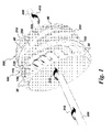
- Fig. 1 represents an embodiment of the invention showing a portion of a supersonic compressor comprising a first supersonic compressor rotor and a second counter-rotary supersonic compressor rotor.
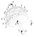
- Fig. 2 represents an embodiment of the invention showing a portion of a supersonic compressor comprising a first supersonic compressor rotor and a second counter-rotary supersonic compressor rotor.
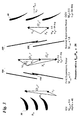
- Fig. 3 represents an embodiment of the invention presented conceptually and illustrating the advantages of coupling a first supersonic compressor rotor with a second counter-rotary supersonic compressor rotor.
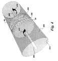
- Fig. 4 represents an embodiment of the invention showing a portion of a supersonic compressor comprising a first supersonic compressor rotor and a second counter-rotary supersonic compressor rotor contained within a housing.
- Fig. 5 represents an embodiment of the invention showing a portion of a supersonic compressor comprising a first supersonic compressor rotor and a second counter-rotary supersonic compressor rotor contained within a housing.
- supersonic compressor refers to a compressor comprising a supersonic compressor rotor.
- Approximating language may be applied to modify any quantitative representation that could permissibly vary without resulting in a change in the basic function to which it is related. Accordingly, a value modified by a term or terms, such as “about” and “substantially”, are not to be limited to the precise value specified. In at least some instances, the approximating language may correspond to the precision of an instrument for measuring the value.
- range limitations may be combined and/or interchanged, such ranges are identified and include all the sub-ranges contained therein unless context or language indicates otherwise.
- the present invention provides a supersonic compressor comprising at least two counter-rotary supersonic compressor rotors configured in series.
- the supersonic compressor provided by the present invention also comprises a fluid inlet and a fluid outlet.
- the supersonic compressors provided by the present invention comprise at least two supersonic compressor rotors configured "in series", meaning that an output from a first supersonic compressor rotor having a first direction of rotation is directed to a second supersonic compressor rotor configured to counter-rotate with respect to the first supersonic compressor rotor.
- Supersonic compressors comprising supersonic compressor rotors are known to those of ordinary skill in the art and are described in detail in, for example, United States Patents numbers 7,334,990 and 7,293,955 filed March 28, 2005 and March 23, 2005 respectively, both of which patents are incorporated herein by reference in their entirety, with the proviso that where the disclosure embodied by either of the referenced patents conflicts with a material portion of the instant Application, the instant Application will be considered authoritative.
- a supersonic compressor rotor is typically a disk having a first face, a second face, and an outer rim, and comprising compression ramps disposed on the outer rim of the disk, said compression ramps being configured to transport a fluid, for example a gas, from the first face of the rotor to the second face of the rotor when the rotor is rotated about its axis of rotation.
- the rotor may be rotated about its axis of rotation by means of a drive shaft coupled to the rotor.
- the rotor is said to be a supersonic compressor rotor because it is designed to rotate about an axis of rotation at high speeds such that a moving fluid, for example a moving gas, encountering the rotating supersonic compressor rotor at a compression ramp disposed upon the rim of the rotor, is said to have a relative fluid velocity which is supersonic.
- the relative fluid velocity can be defined in terms of the vector sum of the rotor velocity at its rim and the fluid velocity prior to encountering the rim of the rotating rotor.
- This relative fluid velocity is at times referred to as the "local supersonic inlet velocity", which in certain embodiments is a combination of an inlet gas velocity and a tangential speed of a supersonic ramp disposed on the rim of a supersonic compressor rotor.
- the supersonic compressor rotors are engineered for service at very high tangential speeds, for example tangential speeds in a range of 300 meters/second to 800 meters/second.
- a supersonic compressor comprises a housing having a gas inlet and a gas outlet, and a supersonic compressor rotor disposed between the gas inlet and the gas outlet.
- the supersonic compressor rotor is equipped with rim surface structures which compress and convey gas from the inlet side of the rotor to the outlet side of the rotor.
- the rim surface structures comprise raised helical structures referred to as strakes, and one or more compression ramps disposed between an upstream strake and a downstream strake.
- the strakes and the compression ramps act in tandem to capture gas at the surface of the rotor nearest the gas inlet, compress the gas between the rotor rim surface and an inner surface of the housing and transfer the gas captured to the outlet surface of the rotor.
- the supersonic compressor rotor is designed such that distance between the strakes on the rotor rim surface and the inner surface of the housing is minimized thereby limiting return passage of gas from the outlet surface of the supersonic compressor rotor to the inlet surface.
- the supersonic compressor provided by the present invention comprises at least two counter rotary supersonic compressor rotors in series such that an output from the first supersonic compressor rotor, for example a compressed gas) is used as the input for a second supersonic compressor rotor rotating in a sense opposite that of the rotation of the first supersonic compressor rotor.
- the first supersonic compressor rotor is configured to rotate in a clockwise manner
- the second supersonic compressor rotor is configured to rotate in a counterclockwise manner.
- the second supersonic compressor rotor is said to be configured to counter-rotate with respect to the first supersonic compressor rotor.
- first and second supersonic compressor rotors are said to be "essentially identical" when each rotor has the same shape, weight and diameter, is made of the same material, and possesses the same type and number of rim surface features.
- first and second supersonic compressor rotors will be mirror images of each other. Arrayed in series, two essentially identical counter-rotary supersonic compressor rotors should be mirror images of one another if the movement of a fluid compressed by the two supersonic compressor rotors is to be in the same primary direction.
- the present invention provides a supersonic compressor comprising a first supersonic compressor rotor which is essentially identical to a second supersonic compressor rotor, the two rotors being configured in series, the two rotors being mirror images of one another, the second supersonic compressor rotor being configured to counter-rotate with respect to the first supersonic compressor rotor.
- the supersonic compressor provided by the present invention comprises two counter-rotary supersonic compressor rotors configured in series, wherein the first supersonic compressor rotor is not identical to the second supersonic compressor rotor.
- two counter-rotary supersonic compressor rotors are not identical when the rotors are materially different in some aspect.
- material differences between two counter-rotary supersonic compressor rotors configured in series include differences in shape, weight and diameter, materials of construction, and type and number of rim surface features.
- two otherwise identical counter-rotary supersonic compressor rotors comprising different numbers of compression ramps would be said to be "not identical".
- the counter-rotary supersonic compressor rotors configured in series share a common axis of rotation, although configurations in which each of the first supersonic compressor rotor and second supersonic compressor rotor has a different axis of rotation are also possible.
- the rotors are said to be arrayed along a common axis of rotation.
- the present invention provides a supersonic compressor comprising a fluid inlet, a fluid outlet, and at least two counter rotary supersonic compressor rotors configured in series, said rotors being arrayed along a common axis of rotation.
- said rotors do not share a common axis of rotation.
- the counter-rotary supersonic compressor rotors may be driven by one or more drive shafts coupled to one or more of the supersonic compressor rotors.
- each of the counter-rotary supersonic compressor rotors is driven by a dedicated drive shaft.
- the present invention provides a supersonic compressor comprising a fluid inlet, a fluid outlet, and at least two counter rotary supersonic compressor rotors configured in series wherein a first supersonic compressor rotor is coupled to a first drive shaft, and said second supersonic compressor rotor is coupled to a second drive shaft, wherein the first and second drive shafts are arrayed a long a common axis of rotation.
- the drive shafts will in various embodiments themselves be configured for counter-rotary motion.
- the first and second drive shafts are counter-rotary, share a common axis of rotation and are concentric, meaning one of the first and second drive shafts is disposed within the other drive shaft.
- the supersonic compressor provided by the present invention comprises first and second drive shafts which are coupled to a common drive motor.
- the supersonic compressor provided by the present invention comprises first and second drive shafts which are coupled to at least two different drive motors.
- the drive motors are used to "drive” (spin) the drive shafts and these in turn drive the supersonic compressor rotors, and understand as well commonly employed means of coupling drive motors (via gears, chains and the like) to drive shafts, and further understand means for controlling the speed at which the drive shafts are spun.
- the first and second drive shafts are driven by a counter-rotary turbine having two sets of blades configured for rotation in opposite directions, the direction of motion of a set of blades being determined by the shape of the constituent blades of each set.
- the present invention provides a supersonic compressor comprising at least three counter-rotary supersonic compressor rotors.
- the supersonic compressor rotors may be configured in series such that an output from a first supersonic compressor rotor having a first direction of rotation is directed to a second supersonic compressor rotor configured to counter-rotate with respect to the first supersonic compressor rotor, and further such that an output from the second supersonic compressor rotor is directed to a third supersonic compressor rotor configured to counter-rotate with respect to the second supersonic compressor rotor.
- the present invention provides a supersonic compressor comprising a fluid inlet, a fluid outlet, at least two counter rotary supersonic compressor rotors configured in series and one or more fluid guide vanes.
- the supersonic compressor may comprise a plurality of fluid guide vanes. The fluid guide vanes may be disposed between the fluid inlet and the first (upstream) supersonic compressor rotor, between the first and second (downstream) supersonic compressor rotors, between the second supersonic compressor rotor and the fluid outlet, or some combination thereof.
- the supersonic compressor provided by the present invention comprises fluid guide vanes disposed between the fluid inlet and the first (upstream) supersonic compressor rotor, in which instance the fluid guide vanes may be referred to logically as inlet guide vanes (IGV).
- the supersonic compressor provided by the present invention comprises fluid guide vanes disposed between the first and second supersonic compressor rotors, in which instance the fluid guide vanes may be referred to logically as intermediate guide vanes (InGV).
- the supersonic compressor provided by the present invention comprises fluid guide vanes disposed between the second supersonic compressor rotor and the fluid outlet, in which instance the fluid guide vanes may be referred to logically as outlet guide vanes (OGV).
- the supersonic compressor provided by the present invention comprises a combination of inlet guide vanes, outlet guide vanes, and intermediate guide vanes disposed between the first and second supersonic compressor rotors.
- the supersonic compressor provided by the present invention further comprises a conventional centrifugal compressor configured to increase the pressure of a gas being presented to a component supersonic compressor rotor.
- the supersonic compressor provided by the present invention comprises a conventional centrifugal compressor between the fluid inlet and the first supersonic compressor rotor.
- that portion of the supersonic compressor located between the fluid inlet and the first supersonic compressor rotor may at times herein be referred to as the low pressure side of the supersonic compressor, and that face of the first supersonic compressor rotor closest to the fluid inlet as the low pressure face of the first supersonic compressor rotor.
- that portion of the supersonic compressor located between the first supersonic compressor rotor and the second supersonic compressor rotor may at times herein be referred to as the intermediate pressure portion of the supersonic compressor.
- that portion of the supersonic compressor located between the second supersonic compressor rotor and the fluid outlet may at times herein be referred to as the high pressure side of the supersonic compressor, and that face of the second supersonic compressor rotor closest to the fluid outlet as the high pressure face of the second supersonic compressor rotor.
- the faces of the first and second supersonic compressor rotors closest to the intermediate pressure portion of the supersonic compressor may at times herein be referred to as the intermediate pressure face of the first supersonic compressor rotor and the intermediate pressure face of the second supersonic compressor rotor respectively.
- the supersonic compressor provided by the present invention is comprised within a larger system, for example a gas turbine engine, for example a jet engine. It is believed that because of the enhanced compression ratios attainable by the supersonic compressors provided by the present invention the overall size and weight of a gas turbine engine may be reduced and attendant benefits derived therefrom.
- the first and second supersonic compressor rotors may be essentially identical, the first and second supersonic compressor rotors being configured such that the two rotors would appear as mirror images of each other through a reflection plane set between them in an idealized space in which both rotors shared a common axis of rotation.
- the first supersonic compressor rotor is not identical to the second counter-rotary supersonic compressor rotor.
- second counter-rotary supersonic compressor rotor and second supersonic compressor rotor are interchangeable.
- the term second counter-rotary supersonic compressor rotor is used to emphasize the fact that the first and second supersonic compressor rotors are configured to be counter rotary (i.e. configured to rotate in opposite directions).
- the first supersonic compressor rotor is coupled to a first drive shaft
- the second counter-rotary supersonic compressor rotor is coupled to a second drive shaft, wherein said first and second drive shafts comprise a pair of concentric, counter-rotary drive shafts.
- Figure 1 illustrates an embodiment of the present invention.
- the figure represents supersonic compressor rotor components and their configuration in a supersonic compressor.
- the supersonic compressor comprises a first supersonic compressor rotor 100 driven by a drive shaft 300 in direction 310.
- the supersonic compressor comprises inlet guide vanes 30 upstream of the first supersonic compressor rotor 100.
- the supersonic compressor comprises a second counter-rotary supersonic compressor rotor 200 configured in series with the first supersonic compressor rotor 100.
- the first supersonic compressor rotor 100 comprises rim surface features which include compression ramps 110 and strakes 150 arrayed on outer surface 110.
- the second supersonic compressor rotor 200 comprises rim surface features which include compression ramps 210 and strakes 250 arrayed on outer surface 210.
- Second supersonic compressor rotor 200 is driven by a drive shaft 400 in direction 410, or counter-rotary with respect to drive shaft 300 and the first supersonic compressor rotor 100.
- the supersonic compressor further comprises outlet guide vanes 40 downstream of the second supersonic compressor rotor 200.
- Figure 2 illustrates an embodiment of the present invention.
- the figure represents supersonic compressor rotor components and their configuration in a supersonic compressor.
- Figure 2 features compression ramps 120 and 220 arrayed on rim surfaces 110 and 210 which differ in structure from compression ramps 120 and 220 featured in. With the exception of the structures of the compression ramps, figures 1 and two are intended to be identical.
- Figure 3 illustrates an embodiment of the present invention presented in a conceptual format and is discussed at length below.
- Figure 4 illustrates an embodiment of the present invention.
- the figure represents supersonic compressor rotor components and their configuration in a supersonic compressor comprising a compressor housing 500 having an inner surface 510.
- the supersonic compressor comprises a first supersonic compressor rotor 100 driven by a drive shaft 300 in direction 310.
- the supersonic compressor comprises inlet guide vanes 30 upstream of the first supersonic compressor rotor 100.
- the supersonic compressor comprises a second counter-rotary supersonic compressor rotor 200 configured in series with the first supersonic compressor rotor 100.
- the first and second supersonic compressor rotors comprise rim surface features including compression ramps and strakes arrayed on the outer surface of the rim.
- Second supersonic compressor rotor 200 is driven by a drive shaft 400 in direction 410, or counter-rotary with respect to drive shaft 300 and the first supersonic compressor rotor 100.
- the supersonic compressor further comprises outlet guide vanes 40 downstream of the second supersonic compressor rotor 200.
- Figure 5 illustrates an embodiment of the present invention.
- the figure represents supersonic compressor rotor components and their configuration in a supersonic compressor comprising a compressor housing 500 having, a gas inlet 10, a gas outlet 20, an inner surface 510, and a gas conduit 520.
- the first supersonic compressor rotor 100 and second supersonic compressor rotor are 200 are shown as disposed within the gas conduit 520.
- Each of the first and second supersonic compressor rotors comprise compression ramps 120 and 220 (respectively) arrayed upon rim surfaces 110 and 210 respectively.
- First supersonic compressor rotor 100 is driven by drive shaft 300 in direction 310.
- Second supersonic compressor rotor 200 is configured to counter-rotate with respect to first supersonic compressor rotor 100.
- Second supersonic compressor rotor 200 is driven by drive shaft 400 in direction 410.
- the supersonic compressor featured in figure 5 comprises inlet guide vanes 30 upstream of first supersonic compressor rotor 100 and outlet guide vanes 40 downstream of second supersonic compressor rotor 200.
- First supersonic compressor rotor 100 and second supersonic compressor rotor 200 are shown configured in series such that the output of first supersonic compressor rotor 100 is used as the input for second supersonic compressor rotor 200.
- Supersonic compressors require high relative velocities of the gas entering the supersonic compression rotor. These velocities must be greater than the local speed of sound in the gas, hence the descriptor "supersonic".
- a gas is introduced through a gas inlet into the supersonic compressor comprising a plurality of inlet guide vanes (IGV) arrayed upstream of a first supersonic compressor rotor, a second supersonic compressor rotor, and a set of outlet guide vanes (OGV).
- IIGV inlet guide vanes
- the gas emerging from the IGV is compressed by the first supersonic compressor rotor and the output of the first supersonic compressor rotor is directed to the second (counter-rotary) supersonic compressor rotor the output of which encounters and is modified by a set of outlet guide vanes (OGV).
- OGV outlet guide vanes
- the gas encounters the inlet guide vanes (IGV)
- the gas is accelerated to a high tangential velocity by the IGV.
- This tangential velocity is combined with the tangential velocity of the rotor and the vector sum of these velocities determines the relative velocity of the gas entering the rotor.
- the acceleration of the gas through the IGV results in a reduction in the local static pressure which must be overcome by the pressure rise in the supersonic compression rotor.
- Equation I The pressure rise across the rotor is a function of the inlet absolute tangential velocity and the exit absolute tangential velocity along with the radius, fluid properties, and rotational speed, and is given by Equation I wherein P 1 is the inlet pressure, P 2 is the exit pressure, ⁇ is a ratio of specific heats of the gas being compressed, ⁇ is the rotational speed, r is the radius, V ⁇ is the tangential velocity, ⁇ (see exponent) is polytropic efficiency, and C 01 is stagnation speed of sound at the inlet which is equal to the square root of ( ⁇ *R*T 0 ) where R is the gas constant and T 0 is the total temperature if the incoming gas.
- Equation I a form of Euler's equation for turbomachinery.
- P 2 P 1 1 + ⁇ - 1 ⁇ ⁇ rv ⁇ C 01 2 ⁇ ⁇ - 1
- Figure 3 illustrates an embodiment of the present invention wherein the ratio of the outlet pressure (Pout) to the inlet pressure (P in ) is 25. Values shown in Figure 3 may be calculated using methods well known to those of ordinary skill in the art.
- Variables shown in figure 3 include: "alpha” (or ⁇ ) which represent an angle relative to stationary inlet guide vanes or outlet guide vanes and referenced to the axis of rotation of the supersonic compressor rotor; "V” which represent velocities relative to a stationary observer such a stationary observer perched on an inlet guide vane or an outlet guide vane; "W” which represent velocities relative to the first supersonic compressor rotor (i.e.
- a gas (not shown) encounters inlet guide vanes (IGV) from which the gas emerges and contacts the first supersonic compressor rotor. The gas then contacts the second counter-rotary supersonic compressor rotor and finally a set of outlet guide vanes (OGV).
- IGV inlet guide vanes
- OOV outlet guide vanes
- the flow leaving the first supersonic rotor has a high absolute Mach number (M 4 ) of 0.8 and a highly tangential flow angle ( ⁇ 4 ) of 77 degrees.
- M 4 absolute Mach number
- ⁇ 4 highly tangential flow angle
- a high speed, swirling flow of this type is difficult to diffuse efficiently using a stationary diffuser.
Landscapes
- Engineering & Computer Science (AREA)
- Mechanical Engineering (AREA)
- General Engineering & Computer Science (AREA)
- Structures Of Non-Positive Displacement Pumps (AREA)
Applications Claiming Priority (1)
| Application Number | Priority Date | Filing Date | Title |
|---|---|---|---|
| US12/342,278 US8137054B2 (en) | 2008-12-23 | 2008-12-23 | Supersonic compressor |
Publications (3)
| Publication Number | Publication Date |
|---|---|
| EP2206928A2 true EP2206928A2 (de) | 2010-07-14 |
| EP2206928A3 EP2206928A3 (de) | 2017-06-07 |
| EP2206928B1 EP2206928B1 (de) | 2019-10-09 |
Family
ID=42035973
Family Applications (1)
| Application Number | Title | Priority Date | Filing Date |
|---|---|---|---|
| EP09178367.0A Active EP2206928B1 (de) | 2008-12-23 | 2009-12-08 | Überschallverdichter |
Country Status (7)
| Country | Link |
|---|---|
| US (1) | US8137054B2 (de) |
| EP (1) | EP2206928B1 (de) |
| JP (1) | JP5607920B2 (de) |
| KR (1) | KR20100074048A (de) |
| CN (1) | CN101813094B (de) |
| CA (1) | CA2687795A1 (de) |
| RU (1) | RU2546350C2 (de) |
Cited By (6)
| Publication number | Priority date | Publication date | Assignee | Title |
|---|---|---|---|---|
| WO2012166564A1 (en) * | 2011-05-27 | 2012-12-06 | General Electric Company | Supersonic compressor rotor and method of compressing a fluid |
| EP2447538A3 (de) * | 2010-10-28 | 2014-11-05 | General Electric Company | System und Verfahren zur Montage eines Überschallverdichtersystems mit Überschallverdichterrotor und Verdichteranordnung |
| EP2466146A3 (de) * | 2010-12-17 | 2014-11-12 | General Electric Company | Überschallverdichter und Verfahren zur seinen Montage |
| RU2594096C2 (ru) * | 2010-11-30 | 2016-08-10 | Дженерал Электрик Компани | Устройство для компрессии диоксида углерода |
| EP2423511B1 (de) * | 2010-08-31 | 2018-05-30 | General Electric Company | Überschallverdichterrotor und Verfahren zu seiner Montage |
| WO2020263614A1 (en) * | 2019-06-28 | 2020-12-30 | Carrier Corporation | Mixed-flow compressor with counter-rotating diffuser |
Families Citing this family (17)
| Publication number | Priority date | Publication date | Assignee | Title |
|---|---|---|---|---|
| US9103345B2 (en) * | 2009-12-16 | 2015-08-11 | General Electric Company | Supersonic compressor rotor |
| US8978380B2 (en) * | 2010-08-10 | 2015-03-17 | Dresser-Rand Company | Adiabatic compressed air energy storage process |
| US8657571B2 (en) * | 2010-12-21 | 2014-02-25 | General Electric Company | Supersonic compressor rotor and methods for assembling same |
| US8550770B2 (en) * | 2011-05-27 | 2013-10-08 | General Electric Company | Supersonic compressor startup support system |
| WO2013009636A2 (en) * | 2011-07-09 | 2013-01-17 | Ramgen Power Systems, Llc | Gas turbine engine with supersonic compressor |
| CN103047154A (zh) * | 2011-07-09 | 2013-04-17 | 拉姆金动力系统有限责任公司 | 超音速压缩机 |
| EP2773854B1 (de) * | 2011-11-03 | 2016-10-19 | Duerr Cyplan Ltd. | Strömungsmaschine |
| CN103573654B (zh) * | 2012-10-13 | 2016-07-06 | 摩尔动力(北京)技术股份有限公司 | 一种多级冲压压气机及应用其的发动机 |
| CN102996404A (zh) * | 2012-12-28 | 2013-03-27 | 深圳市力科气动科技有限公司 | 一种气体压缩机 |
| US9574567B2 (en) * | 2013-10-01 | 2017-02-21 | General Electric Company | Supersonic compressor and associated method |
| US9909597B2 (en) | 2013-10-15 | 2018-03-06 | Dresser-Rand Company | Supersonic compressor with separator |
| CN105626579A (zh) * | 2016-03-04 | 2016-06-01 | 大连海事大学 | 基于激波压缩技术的中空轴旋转冲压压缩转子 |
| CN108131325B (zh) * | 2017-12-19 | 2020-01-24 | 北京理工大学 | 轴向超音通流转叶激波静叶风扇级 |
| CN111622963A (zh) * | 2020-05-26 | 2020-09-04 | 西北工业大学 | 基于冲击式转子-旋转冲压静子的压气机 |
| US12092118B2 (en) | 2021-02-05 | 2024-09-17 | Siemens Energy Global GmbH & Co. KG | Multi-stage compressor assembly having rows of blades arranged to rotate in counter-opposite rotational directions |
| WO2024035894A1 (en) * | 2022-08-11 | 2024-02-15 | Next Gen Compression Llc | Method for efficient part load compressor operation |
| US12066027B2 (en) | 2022-08-11 | 2024-08-20 | Next Gen Compression Llc | Variable geometry supersonic compressor |
Family Cites Families (12)
| Publication number | Priority date | Publication date | Assignee | Title |
|---|---|---|---|---|
| US2623688A (en) * | 1945-12-13 | 1952-12-30 | Power Jets Res & Dev Ltd | Rotary power conversion machine |
| US2689681A (en) * | 1949-09-17 | 1954-09-21 | United Aircraft Corp | Reversely rotating screw type multiple impeller compressor |
| US2955747A (en) * | 1956-06-11 | 1960-10-11 | Snecma | Supersonic axial compressors |
| FR1514932A (fr) * | 1965-06-24 | 1968-03-01 | Snecma | Compresseur axial à double rotor contrarotatif |
| US3797239A (en) * | 1965-10-24 | 1974-03-19 | United Aircraft Corp | Supersonic combustion engine |
| US3546880A (en) * | 1969-08-04 | 1970-12-15 | Avco Corp | Compressors for gas turbine engines |
| US5054996A (en) * | 1990-07-27 | 1991-10-08 | General Electric Company | Thermal linear actuator for rotor air flow control in a gas turbine |
| US7334990B2 (en) * | 2002-01-29 | 2008-02-26 | Ramgen Power Systems, Inc. | Supersonic compressor |
| US7293955B2 (en) * | 2002-09-26 | 2007-11-13 | Ramgen Power Systrms, Inc. | Supersonic gas compressor |
| JP2004232601A (ja) * | 2003-01-31 | 2004-08-19 | Koyo Seiko Co Ltd | 軸流圧縮機 |
| RU2265141C1 (ru) * | 2004-04-12 | 2005-11-27 | Кожевин Виталий Валерьевич | Многоступенчатый компрессор |
| US7966806B2 (en) * | 2006-10-31 | 2011-06-28 | General Electric Company | Turbofan engine assembly and method of assembling same |
-
2008
- 2008-12-23 US US12/342,278 patent/US8137054B2/en active Active
-
2009
- 2009-12-08 EP EP09178367.0A patent/EP2206928B1/de active Active
- 2009-12-10 CA CA2687795A patent/CA2687795A1/en not_active Abandoned
- 2009-12-21 JP JP2009288562A patent/JP5607920B2/ja active Active
- 2009-12-22 RU RU2009147350/06A patent/RU2546350C2/ru active
- 2009-12-22 KR KR1020090128666A patent/KR20100074048A/ko not_active Ceased
- 2009-12-23 CN CN2009102168186A patent/CN101813094B/zh not_active Expired - Fee Related
Cited By (8)
| Publication number | Priority date | Publication date | Assignee | Title |
|---|---|---|---|---|
| EP2423511B1 (de) * | 2010-08-31 | 2018-05-30 | General Electric Company | Überschallverdichterrotor und Verfahren zu seiner Montage |
| EP2447538A3 (de) * | 2010-10-28 | 2014-11-05 | General Electric Company | System und Verfahren zur Montage eines Überschallverdichtersystems mit Überschallverdichterrotor und Verdichteranordnung |
| RU2594096C2 (ru) * | 2010-11-30 | 2016-08-10 | Дженерал Электрик Компани | Устройство для компрессии диоксида углерода |
| EP2466146A3 (de) * | 2010-12-17 | 2014-11-12 | General Electric Company | Überschallverdichter und Verfahren zur seinen Montage |
| WO2012166564A1 (en) * | 2011-05-27 | 2012-12-06 | General Electric Company | Supersonic compressor rotor and method of compressing a fluid |
| US8770929B2 (en) | 2011-05-27 | 2014-07-08 | General Electric Company | Supersonic compressor rotor and method of compressing a fluid |
| WO2020263614A1 (en) * | 2019-06-28 | 2020-12-30 | Carrier Corporation | Mixed-flow compressor with counter-rotating diffuser |
| US11499569B2 (en) | 2019-06-28 | 2022-11-15 | Carrier Corporation | Mixed-flow compressor with counter-rotating diffuser |
Also Published As
| Publication number | Publication date |
|---|---|
| RU2546350C2 (ru) | 2015-04-10 |
| US8137054B2 (en) | 2012-03-20 |
| CN101813094B (zh) | 2013-08-14 |
| RU2009147350A (ru) | 2011-06-27 |
| EP2206928B1 (de) | 2019-10-09 |
| JP2010151135A (ja) | 2010-07-08 |
| JP5607920B2 (ja) | 2014-10-15 |
| EP2206928A3 (de) | 2017-06-07 |
| KR20100074048A (ko) | 2010-07-01 |
| CN101813094A (zh) | 2010-08-25 |
| US20100158665A1 (en) | 2010-06-24 |
| CA2687795A1 (en) | 2010-06-23 |
Similar Documents
| Publication | Publication Date | Title |
|---|---|---|
| EP2206928B1 (de) | Überschallverdichter | |
| US9097258B2 (en) | Supersonic compressor comprising radial flow path | |
| US9163521B2 (en) | Gas turbine engine with supersonic compressor | |
| EP2520763B1 (de) | Laufrad | |
| US9309893B2 (en) | Supersonic compressor | |
| US7334990B2 (en) | Supersonic compressor | |
| CN101769165B (zh) | 带轴流式入口和出口的具有主、闸转子的正位移旋转构件 | |
| EP2447538B1 (de) | System und Verfahren zur Montage eines Überschallverdichtersystems mit Überschallverdichterrotor und Verdichteranordnung | |
| WO2011075204A1 (en) | Supersonic compressor rotor | |
| CN109723559A (zh) | 包括双速分离式压缩机的燃气涡轮发动机 | |
| US20210040958A1 (en) | Centrifugal compressor achieving high pressure ratio | |
| US20030210980A1 (en) | Supersonic compressor | |
| US20040151579A1 (en) | Supersonic gas compressor |
Legal Events
| Date | Code | Title | Description |
|---|---|---|---|
| PUAI | Public reference made under article 153(3) epc to a published international application that has entered the european phase |
Free format text: ORIGINAL CODE: 0009012 |
|
| AK | Designated contracting states |
Kind code of ref document: A2 Designated state(s): AT BE BG CH CY CZ DE DK EE ES FI FR GB GR HR HU IE IS IT LI LT LU LV MC MK MT NL NO PL PT RO SE SI SK SM TR |
|
| AX | Request for extension of the european patent |
Extension state: AL BA RS |
|
| REG | Reference to a national code |
Ref country code: DE Ref legal event code: R079 Ref document number: 602009060061 Country of ref document: DE Free format text: PREVIOUS MAIN CLASS: F04D0017120000 Ipc: F04D0021000000 |
|
| PUAL | Search report despatched |
Free format text: ORIGINAL CODE: 0009013 |
|
| RIC1 | Information provided on ipc code assigned before grant |
Ipc: F04D 21/00 20060101AFI20170403BHEP Ipc: F04D 19/02 20060101ALI20170403BHEP |
|
| AK | Designated contracting states |
Kind code of ref document: A3 Designated state(s): AT BE BG CH CY CZ DE DK EE ES FI FR GB GR HR HU IE IS IT LI LT LU LV MC MK MT NL NO PL PT RO SE SI SK SM TR |
|
| AX | Request for extension of the european patent |
Extension state: AL BA RS |
|
| PUAL | Search report despatched |
Free format text: ORIGINAL CODE: 0009013 |
|
| STAA | Information on the status of an ep patent application or granted ep patent |
Free format text: STATUS: REQUEST FOR EXAMINATION WAS MADE |
|
| 17P | Request for examination filed |
Effective date: 20171207 |
|
| RBV | Designated contracting states (corrected) |
Designated state(s): AT BE BG CH CY CZ DE DK EE ES FI FR GB GR HR HU IE IS IT LI LT LU LV MC MK MT NL NO PL PT RO SE SI SK SM TR |
|
| STAA | Information on the status of an ep patent application or granted ep patent |
Free format text: STATUS: EXAMINATION IS IN PROGRESS |
|
| 17Q | First examination report despatched |
Effective date: 20180626 |
|
| GRAP | Despatch of communication of intention to grant a patent |
Free format text: ORIGINAL CODE: EPIDOSNIGR1 |
|
| STAA | Information on the status of an ep patent application or granted ep patent |
Free format text: STATUS: GRANT OF PATENT IS INTENDED |
|
| INTG | Intention to grant announced |
Effective date: 20190213 |
|
| GRAS | Grant fee paid |
Free format text: ORIGINAL CODE: EPIDOSNIGR3 |
|
| GRAA | (expected) grant |
Free format text: ORIGINAL CODE: 0009210 |
|
| STAA | Information on the status of an ep patent application or granted ep patent |
Free format text: STATUS: THE PATENT HAS BEEN GRANTED |
|
| AK | Designated contracting states |
Kind code of ref document: B1 Designated state(s): AT BE BG CH CY CZ DE DK EE ES FI FR GB GR HR HU IE IS IT LI LT LU LV MC MK MT NL NO PL PT RO SE SI SK SM TR |
|
| REG | Reference to a national code |
Ref country code: GB Ref legal event code: FG4D |
|
| REG | Reference to a national code |
Ref country code: CH Ref legal event code: EP |
|
| REG | Reference to a national code |
Ref country code: IE Ref legal event code: FG4D |
|
| REG | Reference to a national code |
Ref country code: DE Ref legal event code: R096 Ref document number: 602009060061 Country of ref document: DE |
|
| REG | Reference to a national code |
Ref country code: AT Ref legal event code: REF Ref document number: 1189146 Country of ref document: AT Kind code of ref document: T Effective date: 20191115 |
|
| REG | Reference to a national code |
Ref country code: NO Ref legal event code: T2 Effective date: 20191009 |
|
| REG | Reference to a national code |
Ref country code: NL Ref legal event code: MP Effective date: 20191009 |
|
| REG | Reference to a national code |
Ref country code: LT Ref legal event code: MG4D |
|
| PG25 | Lapsed in a contracting state [announced via postgrant information from national office to epo] |
Ref country code: ES Free format text: LAPSE BECAUSE OF FAILURE TO SUBMIT A TRANSLATION OF THE DESCRIPTION OR TO PAY THE FEE WITHIN THE PRESCRIBED TIME-LIMIT Effective date: 20191009 Ref country code: GR Free format text: LAPSE BECAUSE OF FAILURE TO SUBMIT A TRANSLATION OF THE DESCRIPTION OR TO PAY THE FEE WITHIN THE PRESCRIBED TIME-LIMIT Effective date: 20200110 Ref country code: LT Free format text: LAPSE BECAUSE OF FAILURE TO SUBMIT A TRANSLATION OF THE DESCRIPTION OR TO PAY THE FEE WITHIN THE PRESCRIBED TIME-LIMIT Effective date: 20191009 Ref country code: PT Free format text: LAPSE BECAUSE OF FAILURE TO SUBMIT A TRANSLATION OF THE DESCRIPTION OR TO PAY THE FEE WITHIN THE PRESCRIBED TIME-LIMIT Effective date: 20200210 Ref country code: NL Free format text: LAPSE BECAUSE OF FAILURE TO SUBMIT A TRANSLATION OF THE DESCRIPTION OR TO PAY THE FEE WITHIN THE PRESCRIBED TIME-LIMIT Effective date: 20191009 Ref country code: BG Free format text: LAPSE BECAUSE OF FAILURE TO SUBMIT A TRANSLATION OF THE DESCRIPTION OR TO PAY THE FEE WITHIN THE PRESCRIBED TIME-LIMIT Effective date: 20200109 Ref country code: PL Free format text: LAPSE BECAUSE OF FAILURE TO SUBMIT A TRANSLATION OF THE DESCRIPTION OR TO PAY THE FEE WITHIN THE PRESCRIBED TIME-LIMIT Effective date: 20191009 Ref country code: SE Free format text: LAPSE BECAUSE OF FAILURE TO SUBMIT A TRANSLATION OF THE DESCRIPTION OR TO PAY THE FEE WITHIN THE PRESCRIBED TIME-LIMIT Effective date: 20191009 Ref country code: LV Free format text: LAPSE BECAUSE OF FAILURE TO SUBMIT A TRANSLATION OF THE DESCRIPTION OR TO PAY THE FEE WITHIN THE PRESCRIBED TIME-LIMIT Effective date: 20191009 Ref country code: FI Free format text: LAPSE BECAUSE OF FAILURE TO SUBMIT A TRANSLATION OF THE DESCRIPTION OR TO PAY THE FEE WITHIN THE PRESCRIBED TIME-LIMIT Effective date: 20191009 |
|
| PG25 | Lapsed in a contracting state [announced via postgrant information from national office to epo] |
Ref country code: HR Free format text: LAPSE BECAUSE OF FAILURE TO SUBMIT A TRANSLATION OF THE DESCRIPTION OR TO PAY THE FEE WITHIN THE PRESCRIBED TIME-LIMIT Effective date: 20191009 Ref country code: IS Free format text: LAPSE BECAUSE OF FAILURE TO SUBMIT A TRANSLATION OF THE DESCRIPTION OR TO PAY THE FEE WITHIN THE PRESCRIBED TIME-LIMIT Effective date: 20200224 |
|
| REG | Reference to a national code |
Ref country code: DE Ref legal event code: R097 Ref document number: 602009060061 Country of ref document: DE |
|
| PG2D | Information on lapse in contracting state deleted |
Ref country code: IS |
|
| PG25 | Lapsed in a contracting state [announced via postgrant information from national office to epo] |
Ref country code: DK Free format text: LAPSE BECAUSE OF FAILURE TO SUBMIT A TRANSLATION OF THE DESCRIPTION OR TO PAY THE FEE WITHIN THE PRESCRIBED TIME-LIMIT Effective date: 20191009 Ref country code: EE Free format text: LAPSE BECAUSE OF FAILURE TO SUBMIT A TRANSLATION OF THE DESCRIPTION OR TO PAY THE FEE WITHIN THE PRESCRIBED TIME-LIMIT Effective date: 20191009 Ref country code: CZ Free format text: LAPSE BECAUSE OF FAILURE TO SUBMIT A TRANSLATION OF THE DESCRIPTION OR TO PAY THE FEE WITHIN THE PRESCRIBED TIME-LIMIT Effective date: 20191009 Ref country code: RO Free format text: LAPSE BECAUSE OF FAILURE TO SUBMIT A TRANSLATION OF THE DESCRIPTION OR TO PAY THE FEE WITHIN THE PRESCRIBED TIME-LIMIT Effective date: 20191009 Ref country code: IS Free format text: LAPSE BECAUSE OF FAILURE TO SUBMIT A TRANSLATION OF THE DESCRIPTION OR TO PAY THE FEE WITHIN THE PRESCRIBED TIME-LIMIT Effective date: 20200209 |
|
| PLBE | No opposition filed within time limit |
Free format text: ORIGINAL CODE: 0009261 |
|
| STAA | Information on the status of an ep patent application or granted ep patent |
Free format text: STATUS: NO OPPOSITION FILED WITHIN TIME LIMIT |
|
| REG | Reference to a national code |
Ref country code: BE Ref legal event code: MM Effective date: 20191231 |
|
| PG25 | Lapsed in a contracting state [announced via postgrant information from national office to epo] |
Ref country code: SM Free format text: LAPSE BECAUSE OF FAILURE TO SUBMIT A TRANSLATION OF THE DESCRIPTION OR TO PAY THE FEE WITHIN THE PRESCRIBED TIME-LIMIT Effective date: 20191009 Ref country code: SK Free format text: LAPSE BECAUSE OF FAILURE TO SUBMIT A TRANSLATION OF THE DESCRIPTION OR TO PAY THE FEE WITHIN THE PRESCRIBED TIME-LIMIT Effective date: 20191009 Ref country code: MC Free format text: LAPSE BECAUSE OF FAILURE TO SUBMIT A TRANSLATION OF THE DESCRIPTION OR TO PAY THE FEE WITHIN THE PRESCRIBED TIME-LIMIT Effective date: 20191009 |
|
| 26N | No opposition filed |
Effective date: 20200710 |
|
| PG25 | Lapsed in a contracting state [announced via postgrant information from national office to epo] |
Ref country code: IE Free format text: LAPSE BECAUSE OF NON-PAYMENT OF DUE FEES Effective date: 20191208 Ref country code: LU Free format text: LAPSE BECAUSE OF NON-PAYMENT OF DUE FEES Effective date: 20191208 |
|
| PG25 | Lapsed in a contracting state [announced via postgrant information from national office to epo] |
Ref country code: SI Free format text: LAPSE BECAUSE OF FAILURE TO SUBMIT A TRANSLATION OF THE DESCRIPTION OR TO PAY THE FEE WITHIN THE PRESCRIBED TIME-LIMIT Effective date: 20191009 Ref country code: BE Free format text: LAPSE BECAUSE OF NON-PAYMENT OF DUE FEES Effective date: 20191231 |
|
| PG25 | Lapsed in a contracting state [announced via postgrant information from national office to epo] |
Ref country code: CY Free format text: LAPSE BECAUSE OF FAILURE TO SUBMIT A TRANSLATION OF THE DESCRIPTION OR TO PAY THE FEE WITHIN THE PRESCRIBED TIME-LIMIT Effective date: 20191009 |
|
| PG25 | Lapsed in a contracting state [announced via postgrant information from national office to epo] |
Ref country code: MT Free format text: LAPSE BECAUSE OF FAILURE TO SUBMIT A TRANSLATION OF THE DESCRIPTION OR TO PAY THE FEE WITHIN THE PRESCRIBED TIME-LIMIT Effective date: 20191009 Ref country code: HU Free format text: LAPSE BECAUSE OF FAILURE TO SUBMIT A TRANSLATION OF THE DESCRIPTION OR TO PAY THE FEE WITHIN THE PRESCRIBED TIME-LIMIT; INVALID AB INITIO Effective date: 20091208 |
|
| PG25 | Lapsed in a contracting state [announced via postgrant information from national office to epo] |
Ref country code: TR Free format text: LAPSE BECAUSE OF FAILURE TO SUBMIT A TRANSLATION OF THE DESCRIPTION OR TO PAY THE FEE WITHIN THE PRESCRIBED TIME-LIMIT Effective date: 20191009 |
|
| PG25 | Lapsed in a contracting state [announced via postgrant information from national office to epo] |
Ref country code: MK Free format text: LAPSE BECAUSE OF FAILURE TO SUBMIT A TRANSLATION OF THE DESCRIPTION OR TO PAY THE FEE WITHIN THE PRESCRIBED TIME-LIMIT Effective date: 20191009 |
|
| PGFP | Annual fee paid to national office [announced via postgrant information from national office to epo] |
Ref country code: CH Payment date: 20230101 Year of fee payment: 14 |
|
| P01 | Opt-out of the competence of the unified patent court (upc) registered |
Effective date: 20230526 |
|
| REG | Reference to a national code |
Ref country code: AT Ref legal event code: UEP Ref document number: 1189146 Country of ref document: AT Kind code of ref document: T Effective date: 20191009 |
|
| REG | Reference to a national code |
Ref country code: CH Ref legal event code: PL |
|
| PG25 | Lapsed in a contracting state [announced via postgrant information from national office to epo] |
Ref country code: CH Free format text: LAPSE BECAUSE OF NON-PAYMENT OF DUE FEES Effective date: 20231231 |
|
| PG25 | Lapsed in a contracting state [announced via postgrant information from national office to epo] |
Ref country code: CH Free format text: LAPSE BECAUSE OF NON-PAYMENT OF DUE FEES Effective date: 20231231 |
|
| PGFP | Annual fee paid to national office [announced via postgrant information from national office to epo] |
Ref country code: DE Payment date: 20251126 Year of fee payment: 17 |
|
| PGFP | Annual fee paid to national office [announced via postgrant information from national office to epo] |
Ref country code: GB Payment date: 20251120 Year of fee payment: 17 |
|
| PGFP | Annual fee paid to national office [announced via postgrant information from national office to epo] |
Ref country code: NO Payment date: 20251121 Year of fee payment: 17 |
|
| PGFP | Annual fee paid to national office [announced via postgrant information from national office to epo] |
Ref country code: AT Payment date: 20251121 Year of fee payment: 17 |
|
| PGFP | Annual fee paid to national office [announced via postgrant information from national office to epo] |
Ref country code: IT Payment date: 20251119 Year of fee payment: 17 |
|
| PGFP | Annual fee paid to national office [announced via postgrant information from national office to epo] |
Ref country code: FR Payment date: 20251120 Year of fee payment: 17 |