EP2206931A2 - Schraube und ihre Verwendung - Google Patents
Schraube und ihre Verwendung Download PDFInfo
- Publication number
- EP2206931A2 EP2206931A2 EP10150047A EP10150047A EP2206931A2 EP 2206931 A2 EP2206931 A2 EP 2206931A2 EP 10150047 A EP10150047 A EP 10150047A EP 10150047 A EP10150047 A EP 10150047A EP 2206931 A2 EP2206931 A2 EP 2206931A2
- Authority
- EP
- European Patent Office
- Prior art keywords
- screw
- thread
- use according
- section
- drive end
- Prior art date
- Legal status (The legal status is an assumption and is not a legal conclusion. Google has not performed a legal analysis and makes no representation as to the accuracy of the status listed.)
- Granted
Links
Images

Classifications
-
- F—MECHANICAL ENGINEERING; LIGHTING; HEATING; WEAPONS; BLASTING
- F16—ENGINEERING ELEMENTS AND UNITS; GENERAL MEASURES FOR PRODUCING AND MAINTAINING EFFECTIVE FUNCTIONING OF MACHINES OR INSTALLATIONS; THERMAL INSULATION IN GENERAL
- F16B—DEVICES FOR FASTENING OR SECURING CONSTRUCTIONAL ELEMENTS OR MACHINE PARTS TOGETHER, e.g. NAILS, BOLTS, CIRCLIPS, CLAMPS, CLIPS OR WEDGES; JOINTS OR JOINTING
- F16B25/00—Screws that cut thread in the body into which they are screwed, e.g. wood screws
- F16B25/10—Screws performing an additional function to thread-forming, e.g. drill screws or self-piercing screws
- F16B25/106—Screws performing an additional function to thread-forming, e.g. drill screws or self-piercing screws by means of a self-piercing screw-point, i.e. without removing material
-
- F—MECHANICAL ENGINEERING; LIGHTING; HEATING; WEAPONS; BLASTING
- F16—ENGINEERING ELEMENTS AND UNITS; GENERAL MEASURES FOR PRODUCING AND MAINTAINING EFFECTIVE FUNCTIONING OF MACHINES OR INSTALLATIONS; THERMAL INSULATION IN GENERAL
- F16B—DEVICES FOR FASTENING OR SECURING CONSTRUCTIONAL ELEMENTS OR MACHINE PARTS TOGETHER, e.g. NAILS, BOLTS, CIRCLIPS, CLAMPS, CLIPS OR WEDGES; JOINTS OR JOINTING
- F16B25/00—Screws that cut thread in the body into which they are screwed, e.g. wood screws
- F16B25/001—Screws that cut thread in the body into which they are screwed, e.g. wood screws characterised by the material of the body into which the screw is screwed
- F16B25/0031—Screws that cut thread in the body into which they are screwed, e.g. wood screws characterised by the material of the body into which the screw is screwed the screw being designed to be screwed into different materials, e.g. a layered structure or through metallic and wooden parts
-
- F—MECHANICAL ENGINEERING; LIGHTING; HEATING; WEAPONS; BLASTING
- F16—ENGINEERING ELEMENTS AND UNITS; GENERAL MEASURES FOR PRODUCING AND MAINTAINING EFFECTIVE FUNCTIONING OF MACHINES OR INSTALLATIONS; THERMAL INSULATION IN GENERAL
- F16B—DEVICES FOR FASTENING OR SECURING CONSTRUCTIONAL ELEMENTS OR MACHINE PARTS TOGETHER, e.g. NAILS, BOLTS, CIRCLIPS, CLAMPS, CLIPS OR WEDGES; JOINTS OR JOINTING
- F16B25/00—Screws that cut thread in the body into which they are screwed, e.g. wood screws
- F16B25/0036—Screws that cut thread in the body into which they are screwed, e.g. wood screws characterised by geometric details of the screw
- F16B25/0042—Screws that cut thread in the body into which they are screwed, e.g. wood screws characterised by geometric details of the screw characterised by the geometry of the thread, the thread being a ridge wrapped around the shaft of the screw
- F16B25/0057—Screws that cut thread in the body into which they are screwed, e.g. wood screws characterised by geometric details of the screw characterised by the geometry of the thread, the thread being a ridge wrapped around the shaft of the screw the screw having distinct axial zones, e.g. multiple axial thread sections with different pitch or thread cross-sections
- F16B25/0063—Screws that cut thread in the body into which they are screwed, e.g. wood screws characterised by geometric details of the screw characterised by the geometry of the thread, the thread being a ridge wrapped around the shaft of the screw the screw having distinct axial zones, e.g. multiple axial thread sections with different pitch or thread cross-sections with a non-threaded portion on the shaft of the screw
-
- F—MECHANICAL ENGINEERING; LIGHTING; HEATING; WEAPONS; BLASTING
- F16—ENGINEERING ELEMENTS AND UNITS; GENERAL MEASURES FOR PRODUCING AND MAINTAINING EFFECTIVE FUNCTIONING OF MACHINES OR INSTALLATIONS; THERMAL INSULATION IN GENERAL
- F16B—DEVICES FOR FASTENING OR SECURING CONSTRUCTIONAL ELEMENTS OR MACHINE PARTS TOGETHER, e.g. NAILS, BOLTS, CIRCLIPS, CLAMPS, CLIPS OR WEDGES; JOINTS OR JOINTING
- F16B25/00—Screws that cut thread in the body into which they are screwed, e.g. wood screws
- F16B25/0036—Screws that cut thread in the body into which they are screwed, e.g. wood screws characterised by geometric details of the screw
- F16B25/0042—Screws that cut thread in the body into which they are screwed, e.g. wood screws characterised by geometric details of the screw characterised by the geometry of the thread, the thread being a ridge wrapped around the shaft of the screw
- F16B25/0073—Screws that cut thread in the body into which they are screwed, e.g. wood screws characterised by geometric details of the screw characterised by the geometry of the thread, the thread being a ridge wrapped around the shaft of the screw characterised by its pitch, e.g. a varying pitch
-
- F—MECHANICAL ENGINEERING; LIGHTING; HEATING; WEAPONS; BLASTING
- F16—ENGINEERING ELEMENTS AND UNITS; GENERAL MEASURES FOR PRODUCING AND MAINTAINING EFFECTIVE FUNCTIONING OF MACHINES OR INSTALLATIONS; THERMAL INSULATION IN GENERAL
- F16B—DEVICES FOR FASTENING OR SECURING CONSTRUCTIONAL ELEMENTS OR MACHINE PARTS TOGETHER, e.g. NAILS, BOLTS, CIRCLIPS, CLAMPS, CLIPS OR WEDGES; JOINTS OR JOINTING
- F16B35/00—Screw-bolts; Stay-bolts; Screw-threaded studs; Screws; Set screws
- F16B35/04—Screw-bolts; Stay-bolts; Screw-threaded studs; Screws; Set screws with specially-shaped head or shaft in order to fix the bolt on or in an object
- F16B35/06—Specially-shaped heads
-
- F—MECHANICAL ENGINEERING; LIGHTING; HEATING; WEAPONS; BLASTING
- F16—ENGINEERING ELEMENTS AND UNITS; GENERAL MEASURES FOR PRODUCING AND MAINTAINING EFFECTIVE FUNCTIONING OF MACHINES OR INSTALLATIONS; THERMAL INSULATION IN GENERAL
- F16B—DEVICES FOR FASTENING OR SECURING CONSTRUCTIONAL ELEMENTS OR MACHINE PARTS TOGETHER, e.g. NAILS, BOLTS, CIRCLIPS, CLAMPS, CLIPS OR WEDGES; JOINTS OR JOINTING
- F16B5/00—Joining sheets or plates, e.g. panels, to one another or to strips or bars parallel to them
- F16B5/02—Joining sheets or plates, e.g. panels, to one another or to strips or bars parallel to them by means of fastening members using screw-thread
- F16B5/0275—Joining sheets or plates, e.g. panels, to one another or to strips or bars parallel to them by means of fastening members using screw-thread the screw-threaded element having at least two axially separated threaded portions
Definitions
- the invention relates to a screw for attachment of objects to aerated concrete and their use.
- Aerated concrete also called aerated concrete, is a lightly porous mineral lime-sandstone based on lime, lime cement or cement mortar. Due to its low load capacity problems occur when screwing.
- a gas concrete screw is already known ( DE 19852339 ), in which the diameter of the screw shaft increases continuously from the insertion end along a substantial part of the thread.
- the thread edge of the thread is provided in the insertion with a toothing.
- the use of the screw shaft with increasing diameter should lead to a material compaction.
- screws for screwing slats of wood on a roof or wall substructure which have two threaded sections with different pitch ( DE 29805784 ).
- Such screws are not suitable for aerated concrete, because of the different pitch on the front portion of the screw tensile forces are exerted.
- the invention is based on the object to enable a secure attachment of wood elements on aerated concrete.
- the invention proposes a screw with the features mentioned in claim 1 and the use of this screw for mounting on a base of aerated concrete. Further developments of the invention are the subject of the respective subclaims.
- the screw has this at its drive end on a design that allows the attachment of a tool. It may be both a recess in the end of the screw shaft and an external design.
- the drive end of the screw shaft has a screw head, which, however, has a relatively small transverse extent. Its outer diameter should be at most 1.5 times the outer diameter of the holding thread. Preferably, the outer diameter of the screw head is 1.3 times the outer diameter of the holding thread.
- the screw head is only there to receive a recess for applying a tool, but not to transmit axial forces.
- the determination of the object to be fastened is done exclusively via the holding section with its at least partially formed thread.
- the drive end facing away from the front end of the screw shaft may be formed blunt. In this case, pre-drilling in the cellular concrete and the wood is required.
- the screw shaft has an outgoing from the drive end holding portion with an at least partially formed retaining thread, an adjoining thread-free shank portion and a front screw-in with a thread and a front end of the screw, wherein the pitch of the thread in both Thread sections is the same.
- the screw head is a cylinder head.
- the thread in the screw-in and / or in the holding section is a DIN wood thread. This makes the design easier.
- the thread need not be completely chromelidet, it may also be formed here by individual projections which extend approximately radially and are arranged along a helical line.
- the retaining thread is a double-thread, thereby providing a particularly good connection between the screw and the to ensure fastened wood.
- the thread height of the thread in the screw-in is greater than in the holding section.
- the tip is formed as a conical tip, which is also proposed by the invention, need not be pre-drilled in the cellular concrete.
- the screw is coated, in which case in particular a galvanizing or a coating with a zinc flake coating is provided.
- the invention also proposes the use of such a screw for fixing a wooden element to a base consisting of cellular concrete, wherein the fixing of the wooden element is substantially complete by the thread of the screw in this area.
- the attachment is done in such a way that the screw is screwed through the wood element to be fastened into the base of aerated concrete until the outer end of the screw no longer projects beyond the surface of the wood element to be fastened. This can be determined visually very easily.
- the screw When using a screw with a holding portion and a holding thread and with a threaded portion of this separated by a thread-free shank front threaded threaded portion, the screw is used in the manner that the screw-in in the existing aerated concrete pad is disposed while the holding portion is mounted in the wood element to be fastened.
- wood element is used. In general, however, this may also be any other material which may need to be pre-drilled. Under certain circumstances, a thread cutting is required.
- the two threaded sections have the same pitch, it is also possible to attach a wooden element to an aerated concrete underlay with the interposition of an insulating layer.
- This insulating layer is not compressed or deformed. It can be provided in particular that the mentioned unthreaded portion between the two threaded portions is then disposed within the insulating layer.
- the insulating layer may be glass wool, gypsum, aerated concrete, air or similar insulating materials. Since the screw is intended primarily to be used on roofs, can be provided in a development that the screw is screwed at an angle relative to the surface of the wood element, which is in the range of about 60 °.
- the screw is suitable for use on aerated concrete of hardness in the range of PP 4.0.
- the insulating layer may consist of an aerated concrete of 0.5 hardness.
- the thread can have a notch which, for example, extends over the entire length of the thread or only over an area extending from the screw tip in order to reduce the screw-in torque.
- screw in the FIG. 1 illustrated proposed by the invention screw includes a screw shaft 1, which has a constant diameter except for a screw tip 2.
- a screw shaft 1 which has a constant diameter except for a screw tip 2.
- the upper end of a drive end 3 is formed, in the example shown with a screw head 4.
- a screw drive recess is arranged in the end face 5 of the screw head.
- a holding section 6 is formed, in which in the example shown a catchy thread 7 is rolled onto the screw shaft 1.
- a second thread 8 is rolled onto the screw shaft 1, in which it is also a catchy thread. Between the two threaded portions, a thread-free portion 9 is formed where the diameter of the screw shaft is slightly larger than the core diameter in the two, each with a thread 7, 8 provided portions of the screw shaft.
- the diameter of the screw head 4 corresponds to about 1.3 times the outer diameter of the thread 7, 8 in both sections of the screw shaft. 1
- the screw head 4 is a cylinder head whose underside merges rounded into the screw shaft 1.
- the thread In the front region of the screw immediately adjacent to the conical screw tip 2, the thread has a notch 10, which in the cross section of FIG. 3 you can see.
- This notch 10 extends in the illustrated embodiment, only over the front portion of the screw-in, as indicated for example by the route 16.
- the shape of the notch 10 with a flat bottom and two diverging sidewalls is in FIG. 3 shown.
- the notch could also extend over the entire length of the thread 8.
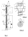
- FIG. 4 shows the application of such a screw in the attachment of a wooden longitudinal slat 11 on a roof structures 12 made of cellular concrete.
- the roof structures 12 consists, as already mentioned, of an aerated concrete. On this relatively solid layer of cellular concrete is a Insulating layer 13 applied, which consists of a heat-insulating but not resilient material. Then longitudinal slats 11 are attached to which then the transverse battens for roof tiles to be attached.
- the attachment using the screws 14 is indicated by dashes.
- the roof runs sloping, for example, at an angle of 45 °.
- the screws 14 are screwed in at a screw-in angle 15 of, for example, 60 ° relative to the surface of the longitudinal slats 11.
- the length of the screws 14 and the three sections is selected so that after the screws 14 have been completely screwed in, the front screw-in section with the screw thread 8 is arranged completely in the cellular concrete 12, that the thread-free section 9 is arranged in the insulating layer 13, and the holding section 6 is arranged in the longitudinal slat 11.
- the longitudinal bar 11 is held on the screw only by the engagement of the thread 7 in the surrounding material.
- the screw head 4 is sunk in this case, but he acts in the determination not or only to a negligible extent.
- FIGS. 1 to 3 is shown as an embodiment of the invention, a screw having two threaded portions which are separated by a thread-free shank portion.
- a second drawing not graphically illustrated embodiment of the invention uses a screw having a similar or the same screw head as the screw of FIG. 1 but in which the thread passes from the bottom of the screw head to the screw tip, without being interrupted by a thread-free shank portion.
- Such a screw which can also be referred to as a threaded rod, may have a front end of a screw, which is constructed as in the screw, which in FIG. 1 is shown. But she can also be a front blunt Have in the end, in which case then the aerated concrete existing base 12 and the wood would have to be pre-drilled.
- a screw having two threaded portions connected by a threadless shank portion is similar to or as in FIG FIG. 1 has a blunt front end.
- a screw For fastening wooden elements to a base made of aerated concrete, in particular for fastening roof battens to roof constructions consisting of cellular concrete, a screw is proposed which has either a thread running through the entire length of the screw or two thread sections separated from each other by a thread-free section whose thread pitches are identical.
- the screw is used so that it is screwed through the wood element into the cellular concrete.
- the determination of the screw on the wood element is done solely by the thread, which is present below the outer end of the screw.
- a possibly existing screw head is designed so small that it exerts substantially no tensile forces on the wood material.
Landscapes
- Engineering & Computer Science (AREA)
- General Engineering & Computer Science (AREA)
- Mechanical Engineering (AREA)
- Physics & Mathematics (AREA)
- Geometry (AREA)
- Joining Of Building Structures In Genera (AREA)
- Door And Window Frames Mounted To Openings (AREA)
- Roof Covering Using Slabs Or Stiff Sheets (AREA)
Abstract
Description
- Die Erfindung betrifft eine Schraube zur Befestigung von Gegenständen an Porenbeton und ihre Verwendung.
- Porenbeton, auch Gasbeton genannt, ist ein leichter poröser mineralischer Kalksandstein auf der Grundlage von Kalk-, Kalkzement oder Zementmörtel. Aufgrund seiner geringen Belastbarkeit treten beim Schrauben Probleme auf.
- Es ist bereits eine Gasbeton-Schraube bekannt (
DE 19852339 ), bei der der Durchmesser des Schraubenschafts von dem Einführende entlang eines wesentlichen Teils des Gewindes stetig zunimmt. Die Gewindekante des Gewindes ist im Einführbereich mit einer Verzahnung versehen. Die Verwendung des Schraubenschafts mit größer werdendem Durchmesser soll zu einer Materialverdichtung führen. - Ebenfalls bekannt sind Schrauben zum Anschrauben von Latten aus Holz auf einem Dach- oder Wandunterbau, die zwei Gewindeabschnitte mit unterschiedlicher Steigung aufweisen (
DE 29805784 ). Derartige Schrauben sind für Gasbeton nicht geeignet, da wegen der unterschiedlichen Steigung auf den vorderen Bereich der Schraube Zugkräfte ausgeübt werden. - Der Erfindung liegt die Aufgabe zu Grunde, eine sichere Befestigung von Holzelementen auf Porenbeton zu ermöglichen.
- Zur Lösung dieser Aufgabe schlägt die Erfindung eine Schraube mit den im Anspruch 1 genannten Merkmalen und die Verwendung dieser Schraube zur Befestigung auf einer Unterlage aus Porenbeton vor. Weiterbildungen der Erfindung sind Gegenstand der jeweiligen Unteransprüche.
- Zum Einschrauben der Schraube weist diese an ihrem Antriebsende eine Gestaltung auf, die das Ansetzen eines Werkzeugs ermöglicht. Es kann sich sowohl um eine Vertiefung in dem Ende des Schraubenschafts als auch um eine äußere Gestaltung handeln. Erfindungsgemäß ist in Weiterbildung auch vorgesehen, dass das Antriebsende des Schraubenschafts einen Schraubenkopf aufweist, der allerdings eine verhältnismäßig kleine Quererstreckung aufweist. Sein Außendurchmesser soll maximal das 1,5-fache des Außendurchmessers des Haltegewindes betragen. Vorzugsweise beträgt der Außendurchmesser des Schraubenkopfs das 1,3-fache des Außendurchmessers des Haltegewindes. Der Schraubenkopf ist nur dazu da, eine Ausnehmung zum Ansetzen eines Werkzeugs aufzunehmen, nicht aber dazu, axiale Kräfte zu übertragen. Die Festlegung des zu befestigenden Gegenstands geschieht ausschließlich über den Halteabschnitt mit seinem mindestens teilweise ausgebildeten Gewinde.
Das dem Antriebsende abgewandte vordere Ende des Schraubenschafts kann stumpf ausgebildet sein. In diesem Fall ist ein Vorbohren in dem Porenbeton und dem Holz erforderlich. - Es kann erfindungsgemäß in Weiterbildung vorgesehen sein, dass der Schraubenschaft einen von dem Antriebsende ausgehenden Halteabschnitt mit einem mindestens teilweise ausgebildeten Haltegewinde, einen sich daran anschließenden gewindefreien Schaftabschnitt und einen vorderen Einschraubabschnitt mit einem Gewinde und einem vorderen Schraubenende aufweist, wobei die Steigung der Gewinde in beiden Gewindeabschnitten gleich ist.
- Dadurch, dass die beiden Gewindeabschnitte die gleiche Steigung aufweisen, wird dann, wenn das Gewinde des Halteabschnitts in dem zu befestigenden Gegenstand eingreift, keine Zugwirkung auf das Gewinde in dem Porenbeton ausgeübt. Die Schraube kann vollständig eingeschraubt werden, ohne dass beim Einschrauben eine Zugwirkung entsteht. Erst nach vollständiger Befestigung kann die Kraft, die an dem befestigten Gegenstand normalerweise angreift, aufgenommen werden.
- Insbesondere kann in Weiterbildung vorgesehen sein, dass der Schraubenkopf ein Zylinderkopf ist.
- In nochmaliger Weiterbildung der Erfindung kann vorgesehen sein, dass das Gewinde in dem Einschraubabschnitt und/oder in dem Halteabschnitt ein DIN Holzgewinde ist. Dadurch gestaltet sich die Bemessung einfacher.
- In dem Halteabschnitt braucht das Gewinde nicht vollständig ausgeblidet zu sein, es kann hier auch durch einzelne Vorsprünge gebildet sein, die angenähert radial verlaufen und längs einer Schraubenlinie angeordnet sind.
- In nochmaliger Weiterbildung der Erfindung kann vorgesehen sein, dass das Haltegewinde ein Doppelganggewinde ist, um dadurch eine besonders gute Verbindung zwischen der Schraube und dem zu befestigenden Holz zu gewährleisten.
- Es hat sich als besonders sinnvoll herausgestellt, dass die Gewindehöhe des Gewindes im Einschraubabschnitt größer ist als im Halteabschnitt.
- Wenn die Spitze als kegelförmige Spitze ausgebildet ist, was von der Erfindung ebenfalls vorgeschlagen wird, braucht in dem Porenbeton nicht vorgebohrt zu werden.
- In nochmaliger Weiterbildung der Erfindung kann vorgesehen sein, dass die Schraube beschichtet ist, wobei hier insbesondere eine Verzinkung oder eine Beschichtung mit einer Zinklamellenbeschichtung vorgesehen ist.
- Die Erfindung schlägt ebenfalls die Verwendung einer solchen Schraube zur Befestigung eines Holzelements an einer Unterlage vor, die aus Porenbeton besteht, wobei die Festlegung des Holzelements im wesentlichen vollständig durch das Gewinde der Schraube in diesem Bereich erfolgt.
- Die Befestigung geschieht derart, dass die Schraube durch das zu befestigende Holzelement hindurch in die Unterlage aus Porenbeton eingeschraubt wird, bis das äußere Ende der Schraube nicht mehr über die Oberfläche des zu befestigenden Holzelements vorsteht. Dies lässt sich optisch sehr einfach feststellen.
- Bei Verwendung einer Schraube mit einem Halteabschnitt und einem Haltegewinde sowie mit einem hiervon durch einen gewindefreien Schaftabschnitt getrennten vorderen Einschraubabschritt mit einem Gewinde wird die Schraube in der Weise verwendet, das der Einschraubabschnitt in der aus Porenbeton bestehenden Unterlage angeordnet ist, während der Halteabschnitt in dem zu befestigenden Holzelement angebracht ist.
- Da die Befestigung an Porenbeton in erster Linie an Dächern geschieht, und bei Dächern traditionell Holz verwendet wird, wird in der hier vorliegenden Beschreibung der Ausdruck Holzelement verwendet. Es kann sich dabei allgemein aber auch um jedes andere Material handeln, das gegebenenfalls vorgebohrt werden muss. Unter Umständen ist auch ein Gewindeschneiden erforderlich.
- Da die beiden Gewindeabschnitte die gleiche Steigung aufweisen, ist es ebenfalls möglich, ein Holzelement an einer Porenbetonunterlage unter Zwischenlage einer Isolierungsschicht zu befestigen. Diese Isolierschicht wird dabei nicht komprimiert oder verformt. Es kann insbesondere vorgesehen sein, dass der erwähnte gewindefreie Abschnitt zwischen den beiden Gewindeabschnitten dann innerhalb der Isolierschicht angeordnet ist. Bei der Isolierschicht kann es sich um Glaswolle, Gips, Porenbeton, Luft oder ähnliche isolierende Stoffe handeln.
Da die Schraube in erster Linie dazu bestimmt ist, an Dächern verwendet zu werden, kann in Weiterbildung vorgesehen sein, dass de Schraube unter einem Winkel gegenüber der Oberfläche des Holzelements eingeschraubt wird, der im Bereich von etwa 60° liegt. - Die Schraube eignet sich der Verwendung an Porenbeton der Härte in einem Bereich von PP 4.0. Auch die Isolierschicht kann aus einem Porenbeton der Härte 0,5 bestehen.
- Erfindungsgemäß kann zur Reduzierung des Einschraubmoments das Gewinde eine Kerbe aufweisen, die beispielsweise über die gesamte Länge des Gewindes oder auch nur über einen von der Schraubenspitze ausgehenden Bereich verläuft.
- Weitere Merkmale, Einzelheiten und Vorzüge der Erfindung ergeben sich aus den Ansprüchen und der Zusammenfassung, deren beider Wortlaut durch Bezugnahme zum Inhalt der Beschreibung gemacht wird, der folgenden Beschreibung bevorzugter Ausführungsformen der Erfindung sowie anhand der Zeichnung. Hierbei zeigen:
- Figur 1
- eine Seitenansicht einer Schraube nach der Erfindung;
- Figur2
- in vergrößertem Maßstab eine Seitenansicht des Antriebsendes der Schraube;
- Figur 3
- einen Querschnitt durch den Schaft der Schraube längs Linie III-III in
Figur 1 ; - Figur 4
- schematisch die Anordnung der Schrauben bei der Befestigung von Längslatten an einem Dach aus Porenbeton.
- Die in
Figur 1 dargestellte von der Erfindung vorgeschlagene Schraube enthält einen Schraubenschaft 1, der mit Ausnahme einer Schraubenspitze 2 einen konstanten Durchmesser aufweist. An dem inFigur 1 oberen Ende ist ein Antriebsende 3 ausgebildet, im dargestellten Beispiel mit einem Schraubenkopf 4. In der Stirnfläche 5 des Schraubenkopfs, die eben ausgebildet ist, ist eine Schraubenantriebsvertiefung angeordnet. - Unmittelbar an den Schraubenkopf 4 anschließend ist ein Halteabschnitt 6 gebildet, in dem im dargestellten Beispiel ein eingängiges Gewinde 7 auf den Schraubenschaft 1 aufgewalzt ist.
- Von der kegelförmigen Schraubenspitze 2 ausgehend ist auf den Schraubenschaft 1 ein zweites Gewinde 8 aufgewalzt, bei dem es sich ebenfalls um ein eingängiges Gewinde handelt. Zwischen beiden Gewindeabschnitten ist ein gewindefreier Abschnitt 9 gebildet wo der Durchmesser des Schraubenschafts etwas größer ist als der Kerndurchmesser in den beiden mit jeweils einem Gewinde 7, 8 versehenen Abschnitten des Schraubenschafts 1.
- Die Steigung beider Gewinde 7 und 8 ist identisch.
- Der Durchmesser des Schraubenkopfs 4 entspricht etwa dem 1,3 fachen des Außendurchmessers des Gewindes 7, 8 in beiden Abschnitten des Schraubenschafts 1.
- Einzelheiten des Schraubenkopfs 4 sind in
Figur 2 dargestellt. Bei dem Schraubenkopf handelt es sich um einen Zylinderkopf, dessen Unterseite abgerundet in den Schraubenschaft 1 übergeht. - In dem vorderen Bereich der Schraube unmittelbar angrenzend an die kegelförmige Schraubenspitze 2 weist das Gewinde eine Kerbe 10 auf, die in dem Querschnitt der
Figur 3 zu sehen ist. Diese Kerbe 10 erstreckt sich im dargestellten Ausführungsbeispiel nur über den vorderen Bereich des Einschraubabschnitts, wie dies beispielsweise durch die Strecke 16 angedeutet ist. Die Form der Kerbe 10 mit einem ebenen Boden und zwei divergierenden Seitenwänden is inFigur 3 dargestellt. Die Kerbe könnte sich auch über die gesamte Länge des Gewindes 8 erstrecken. - Die
Figur 4 , auf die jetzt Bezug genommen wird, zeigt die Anwendung einer solchen Schraube bei der Befestigung einer aus Holz bestehenden Längslatte 11 an einer Dachkonstruktionen 12 aus Porenbeton. - Die Dachkonstruktionen 12 besteht, wie bereits erwähnt, aus einem Porenbeton. Auf diese relativ feste Schicht aus Porenbeton wird eine Isolierschicht 13 aufgebracht, die aus einem Wärme dämmenden aber nicht belastbaren Material besteht. Darauf werden Längslatten 11 angebracht, an denen dann die Querlattung für Dachpfannen befestigt werden soll.
- Die Befestigung mithilfe der Schrauben 14 ist durch Striche angedeutet. Das Dach verläuft abfallend beispielsweise unter einem Winkel von 45°. Die Schrauben 14 werden unter einem Einschraubwinkel 15 von beispielsweise 60° gegenüber der Oberfläche der Längslatten 11 eingeschraubt. Die Länge der Schrauben 14 und der drei Abschnitte ist so gewählt, dass nach dem vollständigen Einschrauben der Schrauben 14 der vordere Einschraubabschnitt mit dem Einschraubgewinde 8 vollständig in dem Porenbeton 12 angeordnet ist, dass der gewindefreie Abschnitt 9 in der Isolierschicht 13 angeordnet ist, und dass der Halteabschnitt 6 in der Längslatte 11 angeordnet ist. Die Längslatte 11 wird an der Schraube nur durch das Eingreifen des Gewindes 7 in das sie umgebende Material gehalten. Der Schraubenkopf 4 wird dabei versenkt, er wirkt aber bei der Festlegung nicht oder nur in vernachlässigbarem Ausmaß mit.
- In den
Figuren 1 bis 3 wird als Ausführungsbeispiel der Erfindung eine Schraube dargestellt, die zwei Gewindeabschnitte aufweist, die durch einen gewindefreien Schaftabschnitt voneinander getrennt sind. Ein zweites zeichnerisch nicht dargestelltes Ausführungsbeispiel der Erfindung verwendet eine Schraube, die einen ähnlichen oder gleichen Schraubenkopf aufweist wie die Schraube derFigur 1 , bei der aber das Gewinde von der Unterseite des Schraubenkopfs bis zur Schraubenspitze durchgeht, ohne durch einen gewindefreien Schaftabschnitt unterbrochen zu sein. Eine solche Schraube, die auch als Gewindestange bezeichnet werden kann, kann ein vorderes Schraubenende aufweisen, das so aufgebaut ist wie bei der Schraube, die inFigur 1 dargestellt ist. Sie kann aber auch ein vorderes stumpfes Ende aufweisen, in welchem Fall dann die aus Porenbeton bestehende Unterlage 12 und das Holz vorgebohrt werden müsste. - Es ist ebenfalls möglich, dass eine Schraube mit zwei durch einen gewindefreien Schaftabschnitt verbundenen Gewindeabschnitten ähnlich wie oder wie in
Figur 1 ein stumpfes vorderes Ende aufweist. - Zur Befestigung von Holzelementen an einer Unterlage aus Porenbeton, insbesondere zur Befestigung von Dachlatten an aus Porenbeton bestehenden Dachkonstruktionen, wird eine Schraube vorgeschlagen, die entweder ein über die gesamte Länge der Schraube durchgehendes Gewinde oder zwei durch einen gewindefreien Abschnitt voneinander getrennte Gewindeabschnitte aufweist, deren Gewindesteigungen identisch sind. Die Schraube wird derart verwendet, dass sie durch das Holzelement hindurch in den Porenbeton eingeschraubt wird. Die Festlegung der Schraube an dem Holzelement geschieht allein durch das Gewinde, das unterhalb des äußeren Endes der Schraube vorhanden ist. Ein möglicherweise vorhandener Schraubenkopf ist so klein ausgebildet, dass er im wesentlichen keine Zugkräfte auf das Holzmaterial ausübt.
Claims (14)
- Schraube zur Befestigung in Porenbeton, mit1.1 einem Schraubenschaft (1),1.2 einem Antriebsende (3), und1.3 einem bis in den Bereich des Antriebsendes (3) reichenden Gewinde (7, 8), wobei1.4 das Antriebsende (3) des Schraubenschafts (1) einen Schraubenkopf (4) aufweist, dessen Außendurchmesser maximal das 1,5-fache des Außendurchmessers des Gewindes (7) beträgt.
- Schraube nach Anspruch 1, bei der der Schraubenschaft (1) einen von dem Antriebsende (3) ausgehenden Halteabschnitt (6) mit einem mindestens teilweise ausgebildeten Haltegewinde (7), einen sich daran anschließenden gewindefreien Schaftabschnitt (9) und einen vorderen Einschraubabschnitt mit einem Gewinde (8) und einem vorderen Schraubenende aufweist, wobei die Steigung der Gewinde (7, 8) in beiden Gewindeabschnitten gleich ist.
- Schraube nach einem Anspruch 2, bei der das Haltegewinde (7) ein Doppelganggewinde ist.
- Schraube nach einem der vorhergehenden Ansprüche, bei der die Gewindehöhe des Gewindes (8) im Einschraubabschnitt größer ist als im Halteabschnitt (6).
- Verwendung einer Schraube nach einem der vorhergehenden Ansprüche zur Befestigung eines Holzelements (11) an einer aus Porenbeton bestehenden Unterlage (12), wobei die Festlegung des Holzelements (11) im wesentlichen vollständig durch das Gewinde (7, 8) erfolgt.
- Verwendung nach Anspruch 5, bei der die Schraube solange eingeschraubt wird, bis die Oberseite des Antriebsendes (3) des Halteabschnitts (6) bündig mit der Oberseite des Holzelements (11) verläuft.
- Verwendung nach Anspruch 5 oder 6, bei der die aus Porenbeton bestehende Unterlage (12) vorgebohrt wird.
- Verwendung nach einem der Ansprüche 5 bis 7, wobei bei einer Schraube nach einem der Ansprüche 2 bis 4 der Halteabschnitt (6) in dem Holzelement (11) und der Einschraubabschnitt in der Unterlage (12) angeordnet wird.
- Verwendung nach einem der Ansprüche 5 bis 8 zur Befestigung eines Holzelements (11) unter Zwischenlage einer Isolierungsschicht (13) an einer Unterlage (12) aus Porenbeton, wobei bei einer Schraube nach einem der Ansprüche 2 bis 4 der gewindefreie Abschnitt (9) in der Isolierungsschicht (13) angeordnet wird.
- Verwendung nach einem der Ansprüche 5 bis 9, bei der die Schraube unter einem Winkel (15) gegenüber der Oberfläche des Holzelements (11) eingeschraubt wird, der im Bereich von etwa 60° liegt.
- Verwendung nach Anspruch 10, bei der der Kosekans des Einschraubwinkels (15) multipliziert mit der Dicke der Isolierschicht (13) der Länge des gewindefreien Abschnitts (9) entspricht.
- Verwendung nach einem der Ansprüche 5 bis 11 zur Befestigung an einem Porenbeton der Härte im Bereich der PP 4.0.
- Verwendung nach einem der Ansprüche 5 bis 12 bei einer Isolierungsschicht (13) aus Porenbeton der Härte 0,5.
- Verwendung nach einem der Ansprüche 5 bis 13, bei dem in dem zu befestigenden Element (11) eine Vorbohrung für die Schraube durchgeführt wird.
Priority Applications (1)
| Application Number | Priority Date | Filing Date | Title |
|---|---|---|---|
| PL10150047T PL2206931T3 (pl) | 2009-01-09 | 2010-01-04 | Śruba i jej zastosowanie |
Applications Claiming Priority (2)
| Application Number | Priority Date | Filing Date | Title |
|---|---|---|---|
| DE102009004639 | 2009-01-09 | ||
| DE102009005916A DE102009005916A1 (de) | 2009-01-09 | 2009-01-20 | Schraube |
Publications (3)
| Publication Number | Publication Date |
|---|---|
| EP2206931A2 true EP2206931A2 (de) | 2010-07-14 |
| EP2206931A3 EP2206931A3 (de) | 2011-04-20 |
| EP2206931B1 EP2206931B1 (de) | 2013-04-17 |
Family
ID=42025783
Family Applications (1)
| Application Number | Title | Priority Date | Filing Date |
|---|---|---|---|
| EP10150047.8A Active EP2206931B1 (de) | 2009-01-09 | 2010-01-04 | Schraube und ihre Verwendung |
Country Status (3)
| Country | Link |
|---|---|
| EP (1) | EP2206931B1 (de) |
| DE (1) | DE102009005916A1 (de) |
| PL (1) | PL2206931T3 (de) |
Cited By (4)
| Publication number | Priority date | Publication date | Assignee | Title |
|---|---|---|---|---|
| WO2013182455A1 (de) * | 2012-06-04 | 2013-12-12 | Swg Schraubenwerk Gaisbach Gmbh | Schraube und verfahren zu ihrer herstellung |
| DE102013210554A1 (de) * | 2013-06-06 | 2014-12-11 | Adolf Würth GmbH & Co. KG | Schraube |
| US20210033137A1 (en) * | 2018-01-18 | 2021-02-04 | Eurospacers Ab | Insulation screw and method for inserting such an insulation screw |
| EP4242476A1 (de) * | 2022-03-09 | 2023-09-13 | Hilti Aktiengesellschaft | Holz-beton-verbundschraube |
Families Citing this family (2)
| Publication number | Priority date | Publication date | Assignee | Title |
|---|---|---|---|---|
| DE102016101519A1 (de) | 2016-01-28 | 2017-08-03 | Sfs Intec Holding Ag | Schraube, Befestigungsanordnung, Verwendung einer Befestigungsanordnung und Verfahren zum Herstellen einer Schraube |
| DE102018209027A1 (de) | 2018-06-07 | 2019-12-12 | Adolf Würth GmbH & Co. KG | Verfahren zum Anordnen einer Porenbetonschraube in Porenbeton, Verwendung und Anordnung |
Citations (2)
| Publication number | Priority date | Publication date | Assignee | Title |
|---|---|---|---|---|
| DE29805784U1 (de) | 1998-03-30 | 1999-08-05 | Sfs Industrie Holding Ag, Heerbrugg | Schraube zur Befestigung von Latten aus Holz auf einem Dach- oder Wandunterbau |
| DE19852339A1 (de) | 1998-11-13 | 2000-05-18 | Toge Duebel A Gerhard Kg | Gasbeton-Schraube |
Family Cites Families (12)
| Publication number | Priority date | Publication date | Assignee | Title |
|---|---|---|---|---|
| DE3718158C2 (de) * | 1987-05-29 | 1996-01-18 | Upat Max Langensiepen Kg | Vorrichtung zur Erzeugung einer Hinterschneidung in einem zylindrisch vorgebohrten Bohrloch |
| DE3740460A1 (de) * | 1987-11-28 | 1989-06-08 | Adolf Wuerth Gmbh & Co Kg | Selbstbohrende schraube |
| DE8804654U1 (de) * | 1988-04-08 | 1988-08-11 | Adolf Würth GmbH & Co. KG, 74653 Künzelsau | Selbstbohrende Schraube |
| CH682830A5 (de) * | 1990-03-28 | 1993-11-30 | August Kunz | Verfahren zur Herstellung eines Unterdachs, Unterdach, hergestellt nach dem Verfahren und Schraube zur Durchführung des Verfahrens. |
| DE29607265U1 (de) * | 1996-04-22 | 1997-06-26 | Sfs Handels Holding Ag, Heerbrugg | Schraube zum Einsatz bei einem Unterdach |
| DE19705202B4 (de) * | 1997-02-12 | 2005-04-14 | Bierbach Gmbh & Co. Kg, Befestigungstechnik | Verfahren zum Befestigen von Holzkonstruktionsteilen vor einer Betonwand oder Mauer |
| ATE244827T1 (de) * | 1997-11-20 | 2003-07-15 | Meyer Liestal Ag | Distanzschraube |
| DE20319768U1 (de) * | 2003-12-19 | 2005-05-04 | Sfs Intec Holding Ag | Schraube |
| DE202004011145U1 (de) * | 2004-07-16 | 2004-09-30 | Duve Kaltformtechnik Gmbh | Gewindeformende Schraube |
| DE202005007886U1 (de) * | 2005-05-19 | 2006-05-18 | Sfs Intec Holding Ag | Wandaufbau bei einem Gebäude |
| DE102007003518B4 (de) * | 2007-01-18 | 2017-12-07 | Adolf Würth GmbH & Co. KG | Schraube, insbesondere zur Durchsteckmontage von Fensterrahmen in der Laibung eines Mauerwerks |
| DE102007029255A1 (de) * | 2007-06-15 | 2008-12-18 | Würth, Adolf | Schraube und ihre Verwendung |
-
2009
- 2009-01-20 DE DE102009005916A patent/DE102009005916A1/de not_active Withdrawn
-
2010
- 2010-01-04 PL PL10150047T patent/PL2206931T3/pl unknown
- 2010-01-04 EP EP10150047.8A patent/EP2206931B1/de active Active
Patent Citations (2)
| Publication number | Priority date | Publication date | Assignee | Title |
|---|---|---|---|---|
| DE29805784U1 (de) | 1998-03-30 | 1999-08-05 | Sfs Industrie Holding Ag, Heerbrugg | Schraube zur Befestigung von Latten aus Holz auf einem Dach- oder Wandunterbau |
| DE19852339A1 (de) | 1998-11-13 | 2000-05-18 | Toge Duebel A Gerhard Kg | Gasbeton-Schraube |
Cited By (6)
| Publication number | Priority date | Publication date | Assignee | Title |
|---|---|---|---|---|
| WO2013182455A1 (de) * | 2012-06-04 | 2013-12-12 | Swg Schraubenwerk Gaisbach Gmbh | Schraube und verfahren zu ihrer herstellung |
| DE102013210554A1 (de) * | 2013-06-06 | 2014-12-11 | Adolf Würth GmbH & Co. KG | Schraube |
| US20210033137A1 (en) * | 2018-01-18 | 2021-02-04 | Eurospacers Ab | Insulation screw and method for inserting such an insulation screw |
| US12152623B2 (en) * | 2018-01-18 | 2024-11-26 | Eurospacers Ab | Insulation screw and method for inserting such an insulation screw |
| EP4242476A1 (de) * | 2022-03-09 | 2023-09-13 | Hilti Aktiengesellschaft | Holz-beton-verbundschraube |
| WO2023169925A1 (en) * | 2022-03-09 | 2023-09-14 | Hilti Aktiengesellschaft | Timber concrete composite screw |
Also Published As
| Publication number | Publication date |
|---|---|
| EP2206931B1 (de) | 2013-04-17 |
| PL2206931T3 (pl) | 2013-09-30 |
| DE102009005916A8 (de) | 2010-12-16 |
| DE102009005916A1 (de) | 2010-07-22 |
| EP2206931A3 (de) | 2011-04-20 |
Similar Documents
| Publication | Publication Date | Title |
|---|---|---|
| EP3365564B1 (de) | Verfahren zur befestigung von anbauteilen an beton oder mauerwerk | |
| EP2206931B1 (de) | Schraube und ihre Verwendung | |
| EP2666919B1 (de) | Verfahren und Befestigungssystem zum Anbringen von Dämmstoffplatten an einem Untergrund | |
| EP1015774B1 (de) | Befestigung von Latten aus Holz auf einem u.a. aus Holz bestehenden Dach- oder Wandunterbau | |
| EP2715156B1 (de) | System zum befestigen einer dämmfassade und dafür vorgesehener befestiger | |
| EP3415773A1 (de) | Schraube mit einem mehrgängigen unterkopfgewinde und befestigungsanordnung hierzu | |
| DE29805784U1 (de) | Schraube zur Befestigung von Latten aus Holz auf einem Dach- oder Wandunterbau | |
| DE102012215645B4 (de) | Schraube und ihre Verwendung | |
| DE202019001906U1 (de) | Einschraubdübel | |
| EP3974667A1 (de) | Stockschraube sowie befestigungssystem mit dieser stockschraube | |
| DE19602400A1 (de) | Holz/Beton-Verbund | |
| DE3611873A1 (de) | Befestigungselement zum verstellbaren befestigen von bauelementen an bauwerken | |
| EP2003348B1 (de) | Schraube und ihre Verwendung | |
| DE102013210554A1 (de) | Schraube | |
| DE102022125079A1 (de) | System zur Befestigung von wetterfesten Beplankungen in Ständerwerken aus Metall oder Holz, deren Verwendung und Montageverfahren | |
| DE102011012776A1 (de) | Verbundschraube für ein Holz-Beton-Tragewerk | |
| EP4234959A1 (de) | Schraube mit im gewinde eingebettetem fräsabschnitt | |
| EP2278172A1 (de) | Vorrichtung zum Befestigen eines Bauelementes in einem Abstand | |
| DE102021118936A1 (de) | Stockschraube sowie Befestigungssystem mit dieser Stockschraube | |
| EP1198676B1 (de) | Anordnung und verfahren zum befestigen von gegenständen | |
| DE10031907A1 (de) | Befestigungselement | |
| DE102006003172A1 (de) | Schraubanker | |
| DE3107403A1 (de) | "schraubnagel" | |
| DE10351884A1 (de) | Befestigungselement | |
| WO2005061908A1 (de) | Schraube |
Legal Events
| Date | Code | Title | Description |
|---|---|---|---|
| PUAI | Public reference made under article 153(3) epc to a published international application that has entered the european phase |
Free format text: ORIGINAL CODE: 0009012 |
|
| AK | Designated contracting states |
Kind code of ref document: A2 Designated state(s): AT BE BG CH CY CZ DE DK EE ES FI FR GB GR HR HU IE IS IT LI LT LU LV MC MK MT NL NO PL PT RO SE SI SK SM TR |
|
| AX | Request for extension of the european patent |
Extension state: AL BA RS |
|
| PUAL | Search report despatched |
Free format text: ORIGINAL CODE: 0009013 |
|
| AK | Designated contracting states |
Kind code of ref document: A3 Designated state(s): AT BE BG CH CY CZ DE DK EE ES FI FR GB GR HR HU IE IS IT LI LT LU LV MC MK MT NL NO PL PT RO SE SI SK SM TR |
|
| AX | Request for extension of the european patent |
Extension state: AL BA RS |
|
| 17P | Request for examination filed |
Effective date: 20111006 |
|
| 17Q | First examination report despatched |
Effective date: 20111122 |
|
| GRAP | Despatch of communication of intention to grant a patent |
Free format text: ORIGINAL CODE: EPIDOSNIGR1 |
|
| RIN1 | Information on inventor provided before grant (corrected) |
Inventor name: KUEENZLEN, JUERGEN Inventor name: WUNDERLICH, ANDREAS |
|
| GRAS | Grant fee paid |
Free format text: ORIGINAL CODE: EPIDOSNIGR3 |
|
| GRAA | (expected) grant |
Free format text: ORIGINAL CODE: 0009210 |
|
| AK | Designated contracting states |
Kind code of ref document: B1 Designated state(s): AT BE BG CH CY CZ DE DK EE ES FI FR GB GR HR HU IE IS IT LI LT LU LV MC MK MT NL NO PL PT RO SE SI SK SM TR |
|
| AX | Request for extension of the european patent |
Extension state: AL BA RS |
|
| REG | Reference to a national code |
Ref country code: GB Ref legal event code: FG4D Free format text: NOT ENGLISH |
|
| REG | Reference to a national code |
Ref country code: CH Ref legal event code: EP |
|
| REG | Reference to a national code |
Ref country code: IE Ref legal event code: FG4D Free format text: LANGUAGE OF EP DOCUMENT: GERMAN |
|
| REG | Reference to a national code |
Ref country code: AT Ref legal event code: REF Ref document number: 607475 Country of ref document: AT Kind code of ref document: T Effective date: 20130515 |
|
| REG | Reference to a national code |
Ref country code: DE Ref legal event code: R096 Ref document number: 502010002922 Country of ref document: DE Effective date: 20130613 |
|
| REG | Reference to a national code |
Ref country code: NL Ref legal event code: T3 |
|
| REG | Reference to a national code |
Ref country code: LT Ref legal event code: MG4D |
|
| REG | Reference to a national code |
Ref country code: PL Ref legal event code: T3 |
|
| PG25 | Lapsed in a contracting state [announced via postgrant information from national office to epo] |
Ref country code: SI Free format text: LAPSE BECAUSE OF FAILURE TO SUBMIT A TRANSLATION OF THE DESCRIPTION OR TO PAY THE FEE WITHIN THE PRESCRIBED TIME-LIMIT Effective date: 20130417 Ref country code: IS Free format text: LAPSE BECAUSE OF FAILURE TO SUBMIT A TRANSLATION OF THE DESCRIPTION OR TO PAY THE FEE WITHIN THE PRESCRIBED TIME-LIMIT Effective date: 20130817 Ref country code: SE Free format text: LAPSE BECAUSE OF FAILURE TO SUBMIT A TRANSLATION OF THE DESCRIPTION OR TO PAY THE FEE WITHIN THE PRESCRIBED TIME-LIMIT Effective date: 20130417 Ref country code: FI Free format text: LAPSE BECAUSE OF FAILURE TO SUBMIT A TRANSLATION OF THE DESCRIPTION OR TO PAY THE FEE WITHIN THE PRESCRIBED TIME-LIMIT Effective date: 20130417 Ref country code: NO Free format text: LAPSE BECAUSE OF FAILURE TO SUBMIT A TRANSLATION OF THE DESCRIPTION OR TO PAY THE FEE WITHIN THE PRESCRIBED TIME-LIMIT Effective date: 20130717 Ref country code: GR Free format text: LAPSE BECAUSE OF FAILURE TO SUBMIT A TRANSLATION OF THE DESCRIPTION OR TO PAY THE FEE WITHIN THE PRESCRIBED TIME-LIMIT Effective date: 20130718 Ref country code: LT Free format text: LAPSE BECAUSE OF FAILURE TO SUBMIT A TRANSLATION OF THE DESCRIPTION OR TO PAY THE FEE WITHIN THE PRESCRIBED TIME-LIMIT Effective date: 20130417 Ref country code: PT Free format text: LAPSE BECAUSE OF FAILURE TO SUBMIT A TRANSLATION OF THE DESCRIPTION OR TO PAY THE FEE WITHIN THE PRESCRIBED TIME-LIMIT Effective date: 20130819 Ref country code: ES Free format text: LAPSE BECAUSE OF FAILURE TO SUBMIT A TRANSLATION OF THE DESCRIPTION OR TO PAY THE FEE WITHIN THE PRESCRIBED TIME-LIMIT Effective date: 20130728 |
|
| PG25 | Lapsed in a contracting state [announced via postgrant information from national office to epo] |
Ref country code: LV Free format text: LAPSE BECAUSE OF FAILURE TO SUBMIT A TRANSLATION OF THE DESCRIPTION OR TO PAY THE FEE WITHIN THE PRESCRIBED TIME-LIMIT Effective date: 20130417 Ref country code: HR Free format text: LAPSE BECAUSE OF FAILURE TO SUBMIT A TRANSLATION OF THE DESCRIPTION OR TO PAY THE FEE WITHIN THE PRESCRIBED TIME-LIMIT Effective date: 20130417 Ref country code: CY Free format text: LAPSE BECAUSE OF FAILURE TO SUBMIT A TRANSLATION OF THE DESCRIPTION OR TO PAY THE FEE WITHIN THE PRESCRIBED TIME-LIMIT Effective date: 20130417 Ref country code: BG Free format text: LAPSE BECAUSE OF FAILURE TO SUBMIT A TRANSLATION OF THE DESCRIPTION OR TO PAY THE FEE WITHIN THE PRESCRIBED TIME-LIMIT Effective date: 20130717 |
|
| PG25 | Lapsed in a contracting state [announced via postgrant information from national office to epo] |
Ref country code: EE Free format text: LAPSE BECAUSE OF FAILURE TO SUBMIT A TRANSLATION OF THE DESCRIPTION OR TO PAY THE FEE WITHIN THE PRESCRIBED TIME-LIMIT Effective date: 20130417 Ref country code: CZ Free format text: LAPSE BECAUSE OF FAILURE TO SUBMIT A TRANSLATION OF THE DESCRIPTION OR TO PAY THE FEE WITHIN THE PRESCRIBED TIME-LIMIT Effective date: 20130417 Ref country code: SK Free format text: LAPSE BECAUSE OF FAILURE TO SUBMIT A TRANSLATION OF THE DESCRIPTION OR TO PAY THE FEE WITHIN THE PRESCRIBED TIME-LIMIT Effective date: 20130417 Ref country code: DK Free format text: LAPSE BECAUSE OF FAILURE TO SUBMIT A TRANSLATION OF THE DESCRIPTION OR TO PAY THE FEE WITHIN THE PRESCRIBED TIME-LIMIT Effective date: 20130417 |
|
| PLBE | No opposition filed within time limit |
Free format text: ORIGINAL CODE: 0009261 |
|
| STAA | Information on the status of an ep patent application or granted ep patent |
Free format text: STATUS: NO OPPOSITION FILED WITHIN TIME LIMIT |
|
| PG25 | Lapsed in a contracting state [announced via postgrant information from national office to epo] |
Ref country code: RO Free format text: LAPSE BECAUSE OF FAILURE TO SUBMIT A TRANSLATION OF THE DESCRIPTION OR TO PAY THE FEE WITHIN THE PRESCRIBED TIME-LIMIT Effective date: 20130417 |
|
| 26N | No opposition filed |
Effective date: 20140120 |
|
| REG | Reference to a national code |
Ref country code: DE Ref legal event code: R097 Ref document number: 502010002922 Country of ref document: DE Effective date: 20140120 |
|
| PG25 | Lapsed in a contracting state [announced via postgrant information from national office to epo] |
Ref country code: LU Free format text: LAPSE BECAUSE OF FAILURE TO SUBMIT A TRANSLATION OF THE DESCRIPTION OR TO PAY THE FEE WITHIN THE PRESCRIBED TIME-LIMIT Effective date: 20140104 Ref country code: MC Free format text: LAPSE BECAUSE OF FAILURE TO SUBMIT A TRANSLATION OF THE DESCRIPTION OR TO PAY THE FEE WITHIN THE PRESCRIBED TIME-LIMIT Effective date: 20130417 |
|
| GBPC | Gb: european patent ceased through non-payment of renewal fee |
Effective date: 20140104 |
|
| REG | Reference to a national code |
Ref country code: IE Ref legal event code: MM4A |
|
| PG25 | Lapsed in a contracting state [announced via postgrant information from national office to epo] |
Ref country code: GB Free format text: LAPSE BECAUSE OF NON-PAYMENT OF DUE FEES Effective date: 20140104 |
|
| PG25 | Lapsed in a contracting state [announced via postgrant information from national office to epo] |
Ref country code: IE Free format text: LAPSE BECAUSE OF NON-PAYMENT OF DUE FEES Effective date: 20140104 |
|
| REG | Reference to a national code |
Ref country code: FR Ref legal event code: PLFP Year of fee payment: 7 |
|
| PG25 | Lapsed in a contracting state [announced via postgrant information from national office to epo] |
Ref country code: MT Free format text: LAPSE BECAUSE OF FAILURE TO SUBMIT A TRANSLATION OF THE DESCRIPTION OR TO PAY THE FEE WITHIN THE PRESCRIBED TIME-LIMIT Effective date: 20130417 |
|
| PG25 | Lapsed in a contracting state [announced via postgrant information from national office to epo] |
Ref country code: SM Free format text: LAPSE BECAUSE OF FAILURE TO SUBMIT A TRANSLATION OF THE DESCRIPTION OR TO PAY THE FEE WITHIN THE PRESCRIBED TIME-LIMIT Effective date: 20130417 |
|
| PG25 | Lapsed in a contracting state [announced via postgrant information from national office to epo] |
Ref country code: HU Free format text: LAPSE BECAUSE OF FAILURE TO SUBMIT A TRANSLATION OF THE DESCRIPTION OR TO PAY THE FEE WITHIN THE PRESCRIBED TIME-LIMIT; INVALID AB INITIO Effective date: 20100104 |
|
| REG | Reference to a national code |
Ref country code: FR Ref legal event code: PLFP Year of fee payment: 8 |
|
| REG | Reference to a national code |
Ref country code: FR Ref legal event code: PLFP Year of fee payment: 9 |
|
| PGFP | Annual fee paid to national office [announced via postgrant information from national office to epo] |
Ref country code: NL Payment date: 20180119 Year of fee payment: 9 |
|
| PGFP | Annual fee paid to national office [announced via postgrant information from national office to epo] |
Ref country code: BE Payment date: 20180119 Year of fee payment: 9 Ref country code: TR Payment date: 20180102 Year of fee payment: 9 |
|
| PG25 | Lapsed in a contracting state [announced via postgrant information from national office to epo] |
Ref country code: MK Free format text: LAPSE BECAUSE OF FAILURE TO SUBMIT A TRANSLATION OF THE DESCRIPTION OR TO PAY THE FEE WITHIN THE PRESCRIBED TIME-LIMIT Effective date: 20130417 |
|
| REG | Reference to a national code |
Ref country code: NL Ref legal event code: MM Effective date: 20190201 |
|
| REG | Reference to a national code |
Ref country code: BE Ref legal event code: MM Effective date: 20190131 |
|
| PG25 | Lapsed in a contracting state [announced via postgrant information from national office to epo] |
Ref country code: NL Free format text: LAPSE BECAUSE OF NON-PAYMENT OF DUE FEES Effective date: 20190201 |
|
| PG25 | Lapsed in a contracting state [announced via postgrant information from national office to epo] |
Ref country code: BE Free format text: LAPSE BECAUSE OF NON-PAYMENT OF DUE FEES Effective date: 20190131 |
|
| PG25 | Lapsed in a contracting state [announced via postgrant information from national office to epo] |
Ref country code: TR Free format text: LAPSE BECAUSE OF NON-PAYMENT OF DUE FEES Effective date: 20190104 |
|
| P01 | Opt-out of the competence of the unified patent court (upc) registered |
Effective date: 20230609 |
|
| PGFP | Annual fee paid to national office [announced via postgrant information from national office to epo] |
Ref country code: PL Payment date: 20231222 Year of fee payment: 15 |
|
| REG | Reference to a national code |
Ref country code: CH Ref legal event code: U11 Free format text: ST27 STATUS EVENT CODE: U-0-0-U10-U11 (AS PROVIDED BY THE NATIONAL OFFICE) Effective date: 20260201 |
|
| PGFP | Annual fee paid to national office [announced via postgrant information from national office to epo] |
Ref country code: DE Payment date: 20260121 Year of fee payment: 17 |
|
| PGFP | Annual fee paid to national office [announced via postgrant information from national office to epo] |
Ref country code: AT Payment date: 20260122 Year of fee payment: 17 |
|
| PGFP | Annual fee paid to national office [announced via postgrant information from national office to epo] |
Ref country code: IT Payment date: 20260126 Year of fee payment: 17 |
|
| PGFP | Annual fee paid to national office [announced via postgrant information from national office to epo] |
Ref country code: FR Payment date: 20260123 Year of fee payment: 17 |
|
| PGFP | Annual fee paid to national office [announced via postgrant information from national office to epo] |
Ref country code: CH Payment date: 20260201 Year of fee payment: 17 |