EP2206931A2 - Vis et son utilisation - Google Patents
Vis et son utilisation Download PDFInfo
- Publication number
- EP2206931A2 EP2206931A2 EP10150047A EP10150047A EP2206931A2 EP 2206931 A2 EP2206931 A2 EP 2206931A2 EP 10150047 A EP10150047 A EP 10150047A EP 10150047 A EP10150047 A EP 10150047A EP 2206931 A2 EP2206931 A2 EP 2206931A2
- Authority
- EP
- European Patent Office
- Prior art keywords
- screw
- thread
- use according
- section
- drive end
- Prior art date
- Legal status (The legal status is an assumption and is not a legal conclusion. Google has not performed a legal analysis and makes no representation as to the accuracy of the status listed.)
- Granted
Links
Images

Classifications
-
- F—MECHANICAL ENGINEERING; LIGHTING; HEATING; WEAPONS; BLASTING
- F16—ENGINEERING ELEMENTS AND UNITS; GENERAL MEASURES FOR PRODUCING AND MAINTAINING EFFECTIVE FUNCTIONING OF MACHINES OR INSTALLATIONS; THERMAL INSULATION IN GENERAL
- F16B—DEVICES FOR FASTENING OR SECURING CONSTRUCTIONAL ELEMENTS OR MACHINE PARTS TOGETHER, e.g. NAILS, BOLTS, CIRCLIPS, CLAMPS, CLIPS OR WEDGES; JOINTS OR JOINTING
- F16B25/00—Screws that cut thread in the body into which they are screwed, e.g. wood screws
- F16B25/10—Screws performing an additional function to thread-forming, e.g. drill screws or self-piercing screws
- F16B25/106—Screws performing an additional function to thread-forming, e.g. drill screws or self-piercing screws by means of a self-piercing screw-point, i.e. without removing material
-
- F—MECHANICAL ENGINEERING; LIGHTING; HEATING; WEAPONS; BLASTING
- F16—ENGINEERING ELEMENTS AND UNITS; GENERAL MEASURES FOR PRODUCING AND MAINTAINING EFFECTIVE FUNCTIONING OF MACHINES OR INSTALLATIONS; THERMAL INSULATION IN GENERAL
- F16B—DEVICES FOR FASTENING OR SECURING CONSTRUCTIONAL ELEMENTS OR MACHINE PARTS TOGETHER, e.g. NAILS, BOLTS, CIRCLIPS, CLAMPS, CLIPS OR WEDGES; JOINTS OR JOINTING
- F16B25/00—Screws that cut thread in the body into which they are screwed, e.g. wood screws
- F16B25/001—Screws that cut thread in the body into which they are screwed, e.g. wood screws characterised by the material of the body into which the screw is screwed
- F16B25/0031—Screws that cut thread in the body into which they are screwed, e.g. wood screws characterised by the material of the body into which the screw is screwed the screw being designed to be screwed into different materials, e.g. a layered structure or through metallic and wooden parts
-
- F—MECHANICAL ENGINEERING; LIGHTING; HEATING; WEAPONS; BLASTING
- F16—ENGINEERING ELEMENTS AND UNITS; GENERAL MEASURES FOR PRODUCING AND MAINTAINING EFFECTIVE FUNCTIONING OF MACHINES OR INSTALLATIONS; THERMAL INSULATION IN GENERAL
- F16B—DEVICES FOR FASTENING OR SECURING CONSTRUCTIONAL ELEMENTS OR MACHINE PARTS TOGETHER, e.g. NAILS, BOLTS, CIRCLIPS, CLAMPS, CLIPS OR WEDGES; JOINTS OR JOINTING
- F16B25/00—Screws that cut thread in the body into which they are screwed, e.g. wood screws
- F16B25/0036—Screws that cut thread in the body into which they are screwed, e.g. wood screws characterised by geometric details of the screw
- F16B25/0042—Screws that cut thread in the body into which they are screwed, e.g. wood screws characterised by geometric details of the screw characterised by the geometry of the thread, the thread being a ridge wrapped around the shaft of the screw
- F16B25/0057—Screws that cut thread in the body into which they are screwed, e.g. wood screws characterised by geometric details of the screw characterised by the geometry of the thread, the thread being a ridge wrapped around the shaft of the screw the screw having distinct axial zones, e.g. multiple axial thread sections with different pitch or thread cross-sections
-
- F—MECHANICAL ENGINEERING; LIGHTING; HEATING; WEAPONS; BLASTING
- F16—ENGINEERING ELEMENTS AND UNITS; GENERAL MEASURES FOR PRODUCING AND MAINTAINING EFFECTIVE FUNCTIONING OF MACHINES OR INSTALLATIONS; THERMAL INSULATION IN GENERAL
- F16B—DEVICES FOR FASTENING OR SECURING CONSTRUCTIONAL ELEMENTS OR MACHINE PARTS TOGETHER, e.g. NAILS, BOLTS, CIRCLIPS, CLAMPS, CLIPS OR WEDGES; JOINTS OR JOINTING
- F16B25/00—Screws that cut thread in the body into which they are screwed, e.g. wood screws
- F16B25/0036—Screws that cut thread in the body into which they are screwed, e.g. wood screws characterised by geometric details of the screw
- F16B25/0042—Screws that cut thread in the body into which they are screwed, e.g. wood screws characterised by geometric details of the screw characterised by the geometry of the thread, the thread being a ridge wrapped around the shaft of the screw
- F16B25/0057—Screws that cut thread in the body into which they are screwed, e.g. wood screws characterised by geometric details of the screw characterised by the geometry of the thread, the thread being a ridge wrapped around the shaft of the screw the screw having distinct axial zones, e.g. multiple axial thread sections with different pitch or thread cross-sections
- F16B25/0063—Screws that cut thread in the body into which they are screwed, e.g. wood screws characterised by geometric details of the screw characterised by the geometry of the thread, the thread being a ridge wrapped around the shaft of the screw the screw having distinct axial zones, e.g. multiple axial thread sections with different pitch or thread cross-sections with a non-threaded portion on the shaft of the screw
-
- F—MECHANICAL ENGINEERING; LIGHTING; HEATING; WEAPONS; BLASTING
- F16—ENGINEERING ELEMENTS AND UNITS; GENERAL MEASURES FOR PRODUCING AND MAINTAINING EFFECTIVE FUNCTIONING OF MACHINES OR INSTALLATIONS; THERMAL INSULATION IN GENERAL
- F16B—DEVICES FOR FASTENING OR SECURING CONSTRUCTIONAL ELEMENTS OR MACHINE PARTS TOGETHER, e.g. NAILS, BOLTS, CIRCLIPS, CLAMPS, CLIPS OR WEDGES; JOINTS OR JOINTING
- F16B25/00—Screws that cut thread in the body into which they are screwed, e.g. wood screws
- F16B25/0036—Screws that cut thread in the body into which they are screwed, e.g. wood screws characterised by geometric details of the screw
- F16B25/0042—Screws that cut thread in the body into which they are screwed, e.g. wood screws characterised by geometric details of the screw characterised by the geometry of the thread, the thread being a ridge wrapped around the shaft of the screw
- F16B25/0073—Screws that cut thread in the body into which they are screwed, e.g. wood screws characterised by geometric details of the screw characterised by the geometry of the thread, the thread being a ridge wrapped around the shaft of the screw characterised by its pitch, e.g. a varying pitch
-
- F—MECHANICAL ENGINEERING; LIGHTING; HEATING; WEAPONS; BLASTING
- F16—ENGINEERING ELEMENTS AND UNITS; GENERAL MEASURES FOR PRODUCING AND MAINTAINING EFFECTIVE FUNCTIONING OF MACHINES OR INSTALLATIONS; THERMAL INSULATION IN GENERAL
- F16B—DEVICES FOR FASTENING OR SECURING CONSTRUCTIONAL ELEMENTS OR MACHINE PARTS TOGETHER, e.g. NAILS, BOLTS, CIRCLIPS, CLAMPS, CLIPS OR WEDGES; JOINTS OR JOINTING
- F16B35/00—Screw-bolts; Stay-bolts; Screw-threaded studs; Screws; Set screws
- F16B35/04—Screw-bolts; Stay-bolts; Screw-threaded studs; Screws; Set screws with specially-shaped head or shaft in order to fix the bolt on or in an object
- F16B35/06—Specially-shaped heads
-
- F—MECHANICAL ENGINEERING; LIGHTING; HEATING; WEAPONS; BLASTING
- F16—ENGINEERING ELEMENTS AND UNITS; GENERAL MEASURES FOR PRODUCING AND MAINTAINING EFFECTIVE FUNCTIONING OF MACHINES OR INSTALLATIONS; THERMAL INSULATION IN GENERAL
- F16B—DEVICES FOR FASTENING OR SECURING CONSTRUCTIONAL ELEMENTS OR MACHINE PARTS TOGETHER, e.g. NAILS, BOLTS, CIRCLIPS, CLAMPS, CLIPS OR WEDGES; JOINTS OR JOINTING
- F16B5/00—Joining sheets or plates, e.g. panels, to one another or to strips or bars parallel to them
- F16B5/02—Joining sheets or plates, e.g. panels, to one another or to strips or bars parallel to them by means of fastening members using screw-thread
- F16B5/0275—Joining sheets or plates, e.g. panels, to one another or to strips or bars parallel to them by means of fastening members using screw-thread the screw-threaded element having at least two axially separated threaded portions
Definitions
- the invention relates to a screw for attachment of objects to aerated concrete and their use.
- Aerated concrete also called aerated concrete, is a lightly porous mineral lime-sandstone based on lime, lime cement or cement mortar. Due to its low load capacity problems occur when screwing.
- a gas concrete screw is already known ( DE 19852339 ), in which the diameter of the screw shaft increases continuously from the insertion end along a substantial part of the thread.
- the thread edge of the thread is provided in the insertion with a toothing.
- the use of the screw shaft with increasing diameter should lead to a material compaction.
- screws for screwing slats of wood on a roof or wall substructure which have two threaded sections with different pitch ( DE 29805784 ).
- Such screws are not suitable for aerated concrete, because of the different pitch on the front portion of the screw tensile forces are exerted.
- the invention is based on the object to enable a secure attachment of wood elements on aerated concrete.
- the invention proposes a screw with the features mentioned in claim 1 and the use of this screw for mounting on a base of aerated concrete. Further developments of the invention are the subject of the respective subclaims.
- the screw has this at its drive end on a design that allows the attachment of a tool. It may be both a recess in the end of the screw shaft and an external design.
- the drive end of the screw shaft has a screw head, which, however, has a relatively small transverse extent. Its outer diameter should be at most 1.5 times the outer diameter of the holding thread. Preferably, the outer diameter of the screw head is 1.3 times the outer diameter of the holding thread.
- the screw head is only there to receive a recess for applying a tool, but not to transmit axial forces.
- the determination of the object to be fastened is done exclusively via the holding section with its at least partially formed thread.
- the drive end facing away from the front end of the screw shaft may be formed blunt. In this case, pre-drilling in the cellular concrete and the wood is required.
- the screw shaft has an outgoing from the drive end holding portion with an at least partially formed retaining thread, an adjoining thread-free shank portion and a front screw-in with a thread and a front end of the screw, wherein the pitch of the thread in both Thread sections is the same.
- the screw head is a cylinder head.
- the thread in the screw-in and / or in the holding section is a DIN wood thread. This makes the design easier.
- the thread need not be completely chromelidet, it may also be formed here by individual projections which extend approximately radially and are arranged along a helical line.
- the retaining thread is a double-thread, thereby providing a particularly good connection between the screw and the to ensure fastened wood.
- the thread height of the thread in the screw-in is greater than in the holding section.
- the tip is formed as a conical tip, which is also proposed by the invention, need not be pre-drilled in the cellular concrete.
- the screw is coated, in which case in particular a galvanizing or a coating with a zinc flake coating is provided.
- the invention also proposes the use of such a screw for fixing a wooden element to a base consisting of cellular concrete, wherein the fixing of the wooden element is substantially complete by the thread of the screw in this area.
- the attachment is done in such a way that the screw is screwed through the wood element to be fastened into the base of aerated concrete until the outer end of the screw no longer projects beyond the surface of the wood element to be fastened. This can be determined visually very easily.
- the screw When using a screw with a holding portion and a holding thread and with a threaded portion of this separated by a thread-free shank front threaded threaded portion, the screw is used in the manner that the screw-in in the existing aerated concrete pad is disposed while the holding portion is mounted in the wood element to be fastened.
- wood element is used. In general, however, this may also be any other material which may need to be pre-drilled. Under certain circumstances, a thread cutting is required.
- the two threaded sections have the same pitch, it is also possible to attach a wooden element to an aerated concrete underlay with the interposition of an insulating layer.
- This insulating layer is not compressed or deformed. It can be provided in particular that the mentioned unthreaded portion between the two threaded portions is then disposed within the insulating layer.
- the insulating layer may be glass wool, gypsum, aerated concrete, air or similar insulating materials. Since the screw is intended primarily to be used on roofs, can be provided in a development that the screw is screwed at an angle relative to the surface of the wood element, which is in the range of about 60 °.
- the screw is suitable for use on aerated concrete of hardness in the range of PP 4.0.
- the insulating layer may consist of an aerated concrete of 0.5 hardness.
- the thread can have a notch which, for example, extends over the entire length of the thread or only over an area extending from the screw tip in order to reduce the screw-in torque.
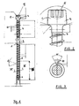
- screw in the FIG. 1 illustrated proposed by the invention screw includes a screw shaft 1, which has a constant diameter except for a screw tip 2.
- a screw shaft 1 which has a constant diameter except for a screw tip 2.
- the upper end of a drive end 3 is formed, in the example shown with a screw head 4.
- a screw drive recess is arranged in the end face 5 of the screw head.
- a holding section 6 is formed, in which in the example shown a catchy thread 7 is rolled onto the screw shaft 1.
- a second thread 8 is rolled onto the screw shaft 1, in which it is also a catchy thread. Between the two threaded portions, a thread-free portion 9 is formed where the diameter of the screw shaft is slightly larger than the core diameter in the two, each with a thread 7, 8 provided portions of the screw shaft.
- the diameter of the screw head 4 corresponds to about 1.3 times the outer diameter of the thread 7, 8 in both sections of the screw shaft. 1
- the screw head 4 is a cylinder head whose underside merges rounded into the screw shaft 1.
- the thread In the front region of the screw immediately adjacent to the conical screw tip 2, the thread has a notch 10, which in the cross section of FIG. 3 you can see.
- This notch 10 extends in the illustrated embodiment, only over the front portion of the screw-in, as indicated for example by the route 16.
- the shape of the notch 10 with a flat bottom and two diverging sidewalls is in FIG. 3 shown.
- the notch could also extend over the entire length of the thread 8.
- FIG. 4 shows the application of such a screw in the attachment of a wooden longitudinal slat 11 on a roof structures 12 made of cellular concrete.
- the roof structures 12 consists, as already mentioned, of an aerated concrete. On this relatively solid layer of cellular concrete is a Insulating layer 13 applied, which consists of a heat-insulating but not resilient material. Then longitudinal slats 11 are attached to which then the transverse battens for roof tiles to be attached.
- the attachment using the screws 14 is indicated by dashes.
- the roof runs sloping, for example, at an angle of 45 °.
- the screws 14 are screwed in at a screw-in angle 15 of, for example, 60 ° relative to the surface of the longitudinal slats 11.
- the length of the screws 14 and the three sections is selected so that after the screws 14 have been completely screwed in, the front screw-in section with the screw thread 8 is arranged completely in the cellular concrete 12, that the thread-free section 9 is arranged in the insulating layer 13, and the holding section 6 is arranged in the longitudinal slat 11.
- the longitudinal bar 11 is held on the screw only by the engagement of the thread 7 in the surrounding material.
- the screw head 4 is sunk in this case, but he acts in the determination not or only to a negligible extent.
- FIGS. 1 to 3 is shown as an embodiment of the invention, a screw having two threaded portions which are separated by a thread-free shank portion.
- a second drawing not graphically illustrated embodiment of the invention uses a screw having a similar or the same screw head as the screw of FIG. 1 but in which the thread passes from the bottom of the screw head to the screw tip, without being interrupted by a thread-free shank portion.
- Such a screw which can also be referred to as a threaded rod, may have a front end of a screw, which is constructed as in the screw, which in FIG. 1 is shown. But she can also be a front blunt Have in the end, in which case then the aerated concrete existing base 12 and the wood would have to be pre-drilled.
- a screw having two threaded portions connected by a threadless shank portion is similar to or as in FIG FIG. 1 has a blunt front end.
- a screw For fastening wooden elements to a base made of aerated concrete, in particular for fastening roof battens to roof constructions consisting of cellular concrete, a screw is proposed which has either a thread running through the entire length of the screw or two thread sections separated from each other by a thread-free section whose thread pitches are identical.
- the screw is used so that it is screwed through the wood element into the cellular concrete.
- the determination of the screw on the wood element is done solely by the thread, which is present below the outer end of the screw.
- a possibly existing screw head is designed so small that it exerts substantially no tensile forces on the wood material.
Landscapes
- Engineering & Computer Science (AREA)
- General Engineering & Computer Science (AREA)
- Mechanical Engineering (AREA)
- Physics & Mathematics (AREA)
- Geometry (AREA)
- Joining Of Building Structures In Genera (AREA)
- Door And Window Frames Mounted To Openings (AREA)
- Roof Covering Using Slabs Or Stiff Sheets (AREA)
Priority Applications (1)
| Application Number | Priority Date | Filing Date | Title |
|---|---|---|---|
| PL10150047T PL2206931T3 (pl) | 2009-01-09 | 2010-01-04 | Śruba i jej zastosowanie |
Applications Claiming Priority (2)
| Application Number | Priority Date | Filing Date | Title |
|---|---|---|---|
| DE102009004639 | 2009-01-09 | ||
| DE102009005916A DE102009005916A1 (de) | 2009-01-09 | 2009-01-20 | Schraube |
Publications (3)
| Publication Number | Publication Date |
|---|---|
| EP2206931A2 true EP2206931A2 (fr) | 2010-07-14 |
| EP2206931A3 EP2206931A3 (fr) | 2011-04-20 |
| EP2206931B1 EP2206931B1 (fr) | 2013-04-17 |
Family
ID=42025783
Family Applications (1)
| Application Number | Title | Priority Date | Filing Date |
|---|---|---|---|
| EP10150047.8A Active EP2206931B1 (fr) | 2009-01-09 | 2010-01-04 | Vis et son utilisation |
Country Status (3)
| Country | Link |
|---|---|
| EP (1) | EP2206931B1 (fr) |
| DE (1) | DE102009005916A1 (fr) |
| PL (1) | PL2206931T3 (fr) |
Cited By (4)
| Publication number | Priority date | Publication date | Assignee | Title |
|---|---|---|---|---|
| WO2013182455A1 (fr) * | 2012-06-04 | 2013-12-12 | Swg Schraubenwerk Gaisbach Gmbh | Vis et procédé de fabrication de ladite vis |
| DE102013210554A1 (de) * | 2013-06-06 | 2014-12-11 | Adolf Würth GmbH & Co. KG | Schraube |
| US20210033137A1 (en) * | 2018-01-18 | 2021-02-04 | Eurospacers Ab | Insulation screw and method for inserting such an insulation screw |
| EP4242476A1 (fr) * | 2022-03-09 | 2023-09-13 | Hilti Aktiengesellschaft | Vis composite bois béton |
Families Citing this family (2)
| Publication number | Priority date | Publication date | Assignee | Title |
|---|---|---|---|---|
| DE102016101519A1 (de) | 2016-01-28 | 2017-08-03 | Sfs Intec Holding Ag | Schraube, Befestigungsanordnung, Verwendung einer Befestigungsanordnung und Verfahren zum Herstellen einer Schraube |
| DE102018209027A1 (de) | 2018-06-07 | 2019-12-12 | Adolf Würth GmbH & Co. KG | Verfahren zum Anordnen einer Porenbetonschraube in Porenbeton, Verwendung und Anordnung |
Citations (2)
| Publication number | Priority date | Publication date | Assignee | Title |
|---|---|---|---|---|
| DE29805784U1 (de) | 1998-03-30 | 1999-08-05 | Sfs Industrie Holding Ag, Heerbrugg | Schraube zur Befestigung von Latten aus Holz auf einem Dach- oder Wandunterbau |
| DE19852339A1 (de) | 1998-11-13 | 2000-05-18 | Toge Duebel A Gerhard Kg | Gasbeton-Schraube |
Family Cites Families (12)
| Publication number | Priority date | Publication date | Assignee | Title |
|---|---|---|---|---|
| DE3718158C2 (de) * | 1987-05-29 | 1996-01-18 | Upat Max Langensiepen Kg | Vorrichtung zur Erzeugung einer Hinterschneidung in einem zylindrisch vorgebohrten Bohrloch |
| DE8804654U1 (de) * | 1988-04-08 | 1988-08-11 | Adolf Würth GmbH & Co. KG, 74653 Künzelsau | Selbstbohrende Schraube |
| DE3740460A1 (de) * | 1987-11-28 | 1989-06-08 | Adolf Wuerth Gmbh & Co Kg | Selbstbohrende schraube |
| CH682830A5 (de) * | 1990-03-28 | 1993-11-30 | August Kunz | Verfahren zur Herstellung eines Unterdachs, Unterdach, hergestellt nach dem Verfahren und Schraube zur Durchführung des Verfahrens. |
| DE29607265U1 (de) * | 1996-04-22 | 1997-06-26 | Sfs Handels Holding Ag, Heerbrugg | Schraube zum Einsatz bei einem Unterdach |
| DE19705202B4 (de) * | 1997-02-12 | 2005-04-14 | Bierbach Gmbh & Co. Kg, Befestigungstechnik | Verfahren zum Befestigen von Holzkonstruktionsteilen vor einer Betonwand oder Mauer |
| ATE244827T1 (de) * | 1997-11-20 | 2003-07-15 | Meyer Liestal Ag | Distanzschraube |
| DE20319768U1 (de) * | 2003-12-19 | 2005-05-04 | Sfs Intec Holding Ag | Schraube |
| DE202004011145U1 (de) * | 2004-07-16 | 2004-09-30 | Duve Kaltformtechnik Gmbh | Gewindeformende Schraube |
| DE202005007886U1 (de) * | 2005-05-19 | 2006-05-18 | Sfs Intec Holding Ag | Wandaufbau bei einem Gebäude |
| DE102007003518B4 (de) * | 2007-01-18 | 2017-12-07 | Adolf Würth GmbH & Co. KG | Schraube, insbesondere zur Durchsteckmontage von Fensterrahmen in der Laibung eines Mauerwerks |
| DE102007029255A1 (de) * | 2007-06-15 | 2008-12-18 | Würth, Adolf | Schraube und ihre Verwendung |
-
2009
- 2009-01-20 DE DE102009005916A patent/DE102009005916A1/de not_active Withdrawn
-
2010
- 2010-01-04 PL PL10150047T patent/PL2206931T3/pl unknown
- 2010-01-04 EP EP10150047.8A patent/EP2206931B1/fr active Active
Patent Citations (2)
| Publication number | Priority date | Publication date | Assignee | Title |
|---|---|---|---|---|
| DE29805784U1 (de) | 1998-03-30 | 1999-08-05 | Sfs Industrie Holding Ag, Heerbrugg | Schraube zur Befestigung von Latten aus Holz auf einem Dach- oder Wandunterbau |
| DE19852339A1 (de) | 1998-11-13 | 2000-05-18 | Toge Duebel A Gerhard Kg | Gasbeton-Schraube |
Cited By (6)
| Publication number | Priority date | Publication date | Assignee | Title |
|---|---|---|---|---|
| WO2013182455A1 (fr) * | 2012-06-04 | 2013-12-12 | Swg Schraubenwerk Gaisbach Gmbh | Vis et procédé de fabrication de ladite vis |
| DE102013210554A1 (de) * | 2013-06-06 | 2014-12-11 | Adolf Würth GmbH & Co. KG | Schraube |
| US20210033137A1 (en) * | 2018-01-18 | 2021-02-04 | Eurospacers Ab | Insulation screw and method for inserting such an insulation screw |
| US12152623B2 (en) * | 2018-01-18 | 2024-11-26 | Eurospacers Ab | Insulation screw and method for inserting such an insulation screw |
| EP4242476A1 (fr) * | 2022-03-09 | 2023-09-13 | Hilti Aktiengesellschaft | Vis composite bois béton |
| WO2023169925A1 (fr) * | 2022-03-09 | 2023-09-14 | Hilti Aktiengesellschaft | Vis composite en béton et bois |
Also Published As
| Publication number | Publication date |
|---|---|
| EP2206931B1 (fr) | 2013-04-17 |
| DE102009005916A8 (de) | 2010-12-16 |
| DE102009005916A1 (de) | 2010-07-22 |
| EP2206931A3 (fr) | 2011-04-20 |
| PL2206931T3 (pl) | 2013-09-30 |
Similar Documents
| Publication | Publication Date | Title |
|---|---|---|
| EP3365564B1 (fr) | Procédé permettant de fixer des pièces rapportées à du béton ou à une maçonnerie | |
| EP2206931B1 (fr) | Vis et son utilisation | |
| EP2666919B1 (fr) | Procédé et système de fixation pour le montage de plaques d'isolant sur une surface de support | |
| EP1015774B1 (fr) | Fixation des lattes de bois sur le platelage d'un toit ou la fondation d'un mur composé entre autres de bois | |
| EP2715156B1 (fr) | Système de fixation d'une façade isolante et dispositif de fixation prévu à cet effet | |
| EP3415773A1 (fr) | Vis comprenant un filetage sous tête à filets multiples et système de fixation associé | |
| DE29805784U1 (de) | Schraube zur Befestigung von Latten aus Holz auf einem Dach- oder Wandunterbau | |
| DE102012215645B4 (de) | Schraube und ihre Verwendung | |
| DE102010040024A1 (de) | Schraube | |
| DE202019001906U1 (de) | Einschraubdübel | |
| EP4234959A1 (fr) | Vis pourvue de section fraiseuse noyée dans le filetage | |
| EP2003348B1 (fr) | Vis et son utilisation | |
| EP3974667A1 (fr) | Vis à double filetage et système de fixation pourvu de ladite vis à double filetage | |
| DE19602400A1 (de) | Holz/Beton-Verbund | |
| DE102013210554A1 (de) | Schraube | |
| DE3611873A1 (de) | Befestigungselement zum verstellbaren befestigen von bauelementen an bauwerken | |
| DE102022125079A1 (de) | System zur Befestigung von wetterfesten Beplankungen in Ständerwerken aus Metall oder Holz, deren Verwendung und Montageverfahren | |
| DE102011012776A1 (de) | Verbundschraube für ein Holz-Beton-Tragewerk | |
| EP2278172A1 (fr) | Dispositif de fixation d'un élément de construction dans un espacement | |
| DE102021118936A1 (de) | Stockschraube sowie Befestigungssystem mit dieser Stockschraube | |
| EP1198676B1 (fr) | Dispositif et procede de fixation d'objets | |
| DE10031907A1 (de) | Befestigungselement | |
| DE102006003172A1 (de) | Schraubanker | |
| DE3107403A1 (de) | "schraubnagel" | |
| DE10351884A1 (de) | Befestigungselement |
Legal Events
| Date | Code | Title | Description |
|---|---|---|---|
| PUAI | Public reference made under article 153(3) epc to a published international application that has entered the european phase |
Free format text: ORIGINAL CODE: 0009012 |
|
| AK | Designated contracting states |
Kind code of ref document: A2 Designated state(s): AT BE BG CH CY CZ DE DK EE ES FI FR GB GR HR HU IE IS IT LI LT LU LV MC MK MT NL NO PL PT RO SE SI SK SM TR |
|
| AX | Request for extension of the european patent |
Extension state: AL BA RS |
|
| PUAL | Search report despatched |
Free format text: ORIGINAL CODE: 0009013 |
|
| AK | Designated contracting states |
Kind code of ref document: A3 Designated state(s): AT BE BG CH CY CZ DE DK EE ES FI FR GB GR HR HU IE IS IT LI LT LU LV MC MK MT NL NO PL PT RO SE SI SK SM TR |
|
| AX | Request for extension of the european patent |
Extension state: AL BA RS |
|
| 17P | Request for examination filed |
Effective date: 20111006 |
|
| 17Q | First examination report despatched |
Effective date: 20111122 |
|
| GRAP | Despatch of communication of intention to grant a patent |
Free format text: ORIGINAL CODE: EPIDOSNIGR1 |
|
| RIN1 | Information on inventor provided before grant (corrected) |
Inventor name: KUEENZLEN, JUERGEN Inventor name: WUNDERLICH, ANDREAS |
|
| GRAS | Grant fee paid |
Free format text: ORIGINAL CODE: EPIDOSNIGR3 |
|
| GRAA | (expected) grant |
Free format text: ORIGINAL CODE: 0009210 |
|
| AK | Designated contracting states |
Kind code of ref document: B1 Designated state(s): AT BE BG CH CY CZ DE DK EE ES FI FR GB GR HR HU IE IS IT LI LT LU LV MC MK MT NL NO PL PT RO SE SI SK SM TR |
|
| AX | Request for extension of the european patent |
Extension state: AL BA RS |
|
| REG | Reference to a national code |
Ref country code: GB Ref legal event code: FG4D Free format text: NOT ENGLISH |
|
| REG | Reference to a national code |
Ref country code: CH Ref legal event code: EP |
|
| REG | Reference to a national code |
Ref country code: IE Ref legal event code: FG4D Free format text: LANGUAGE OF EP DOCUMENT: GERMAN |
|
| REG | Reference to a national code |
Ref country code: AT Ref legal event code: REF Ref document number: 607475 Country of ref document: AT Kind code of ref document: T Effective date: 20130515 |
|
| REG | Reference to a national code |
Ref country code: DE Ref legal event code: R096 Ref document number: 502010002922 Country of ref document: DE Effective date: 20130613 |
|
| REG | Reference to a national code |
Ref country code: NL Ref legal event code: T3 |
|
| REG | Reference to a national code |
Ref country code: LT Ref legal event code: MG4D |
|
| REG | Reference to a national code |
Ref country code: PL Ref legal event code: T3 |
|
| PG25 | Lapsed in a contracting state [announced via postgrant information from national office to epo] |
Ref country code: SI Free format text: LAPSE BECAUSE OF FAILURE TO SUBMIT A TRANSLATION OF THE DESCRIPTION OR TO PAY THE FEE WITHIN THE PRESCRIBED TIME-LIMIT Effective date: 20130417 Ref country code: IS Free format text: LAPSE BECAUSE OF FAILURE TO SUBMIT A TRANSLATION OF THE DESCRIPTION OR TO PAY THE FEE WITHIN THE PRESCRIBED TIME-LIMIT Effective date: 20130817 Ref country code: SE Free format text: LAPSE BECAUSE OF FAILURE TO SUBMIT A TRANSLATION OF THE DESCRIPTION OR TO PAY THE FEE WITHIN THE PRESCRIBED TIME-LIMIT Effective date: 20130417 Ref country code: FI Free format text: LAPSE BECAUSE OF FAILURE TO SUBMIT A TRANSLATION OF THE DESCRIPTION OR TO PAY THE FEE WITHIN THE PRESCRIBED TIME-LIMIT Effective date: 20130417 Ref country code: NO Free format text: LAPSE BECAUSE OF FAILURE TO SUBMIT A TRANSLATION OF THE DESCRIPTION OR TO PAY THE FEE WITHIN THE PRESCRIBED TIME-LIMIT Effective date: 20130717 Ref country code: GR Free format text: LAPSE BECAUSE OF FAILURE TO SUBMIT A TRANSLATION OF THE DESCRIPTION OR TO PAY THE FEE WITHIN THE PRESCRIBED TIME-LIMIT Effective date: 20130718 Ref country code: LT Free format text: LAPSE BECAUSE OF FAILURE TO SUBMIT A TRANSLATION OF THE DESCRIPTION OR TO PAY THE FEE WITHIN THE PRESCRIBED TIME-LIMIT Effective date: 20130417 Ref country code: PT Free format text: LAPSE BECAUSE OF FAILURE TO SUBMIT A TRANSLATION OF THE DESCRIPTION OR TO PAY THE FEE WITHIN THE PRESCRIBED TIME-LIMIT Effective date: 20130819 Ref country code: ES Free format text: LAPSE BECAUSE OF FAILURE TO SUBMIT A TRANSLATION OF THE DESCRIPTION OR TO PAY THE FEE WITHIN THE PRESCRIBED TIME-LIMIT Effective date: 20130728 |
|
| PG25 | Lapsed in a contracting state [announced via postgrant information from national office to epo] |
Ref country code: LV Free format text: LAPSE BECAUSE OF FAILURE TO SUBMIT A TRANSLATION OF THE DESCRIPTION OR TO PAY THE FEE WITHIN THE PRESCRIBED TIME-LIMIT Effective date: 20130417 Ref country code: HR Free format text: LAPSE BECAUSE OF FAILURE TO SUBMIT A TRANSLATION OF THE DESCRIPTION OR TO PAY THE FEE WITHIN THE PRESCRIBED TIME-LIMIT Effective date: 20130417 Ref country code: CY Free format text: LAPSE BECAUSE OF FAILURE TO SUBMIT A TRANSLATION OF THE DESCRIPTION OR TO PAY THE FEE WITHIN THE PRESCRIBED TIME-LIMIT Effective date: 20130417 Ref country code: BG Free format text: LAPSE BECAUSE OF FAILURE TO SUBMIT A TRANSLATION OF THE DESCRIPTION OR TO PAY THE FEE WITHIN THE PRESCRIBED TIME-LIMIT Effective date: 20130717 |
|
| PG25 | Lapsed in a contracting state [announced via postgrant information from national office to epo] |
Ref country code: EE Free format text: LAPSE BECAUSE OF FAILURE TO SUBMIT A TRANSLATION OF THE DESCRIPTION OR TO PAY THE FEE WITHIN THE PRESCRIBED TIME-LIMIT Effective date: 20130417 Ref country code: CZ Free format text: LAPSE BECAUSE OF FAILURE TO SUBMIT A TRANSLATION OF THE DESCRIPTION OR TO PAY THE FEE WITHIN THE PRESCRIBED TIME-LIMIT Effective date: 20130417 Ref country code: SK Free format text: LAPSE BECAUSE OF FAILURE TO SUBMIT A TRANSLATION OF THE DESCRIPTION OR TO PAY THE FEE WITHIN THE PRESCRIBED TIME-LIMIT Effective date: 20130417 Ref country code: DK Free format text: LAPSE BECAUSE OF FAILURE TO SUBMIT A TRANSLATION OF THE DESCRIPTION OR TO PAY THE FEE WITHIN THE PRESCRIBED TIME-LIMIT Effective date: 20130417 |
|
| PLBE | No opposition filed within time limit |
Free format text: ORIGINAL CODE: 0009261 |
|
| STAA | Information on the status of an ep patent application or granted ep patent |
Free format text: STATUS: NO OPPOSITION FILED WITHIN TIME LIMIT |
|
| PG25 | Lapsed in a contracting state [announced via postgrant information from national office to epo] |
Ref country code: RO Free format text: LAPSE BECAUSE OF FAILURE TO SUBMIT A TRANSLATION OF THE DESCRIPTION OR TO PAY THE FEE WITHIN THE PRESCRIBED TIME-LIMIT Effective date: 20130417 |
|
| 26N | No opposition filed |
Effective date: 20140120 |
|
| REG | Reference to a national code |
Ref country code: DE Ref legal event code: R097 Ref document number: 502010002922 Country of ref document: DE Effective date: 20140120 |
|
| PG25 | Lapsed in a contracting state [announced via postgrant information from national office to epo] |
Ref country code: LU Free format text: LAPSE BECAUSE OF FAILURE TO SUBMIT A TRANSLATION OF THE DESCRIPTION OR TO PAY THE FEE WITHIN THE PRESCRIBED TIME-LIMIT Effective date: 20140104 Ref country code: MC Free format text: LAPSE BECAUSE OF FAILURE TO SUBMIT A TRANSLATION OF THE DESCRIPTION OR TO PAY THE FEE WITHIN THE PRESCRIBED TIME-LIMIT Effective date: 20130417 |
|
| GBPC | Gb: european patent ceased through non-payment of renewal fee |
Effective date: 20140104 |
|
| REG | Reference to a national code |
Ref country code: IE Ref legal event code: MM4A |
|
| PG25 | Lapsed in a contracting state [announced via postgrant information from national office to epo] |
Ref country code: GB Free format text: LAPSE BECAUSE OF NON-PAYMENT OF DUE FEES Effective date: 20140104 |
|
| PG25 | Lapsed in a contracting state [announced via postgrant information from national office to epo] |
Ref country code: IE Free format text: LAPSE BECAUSE OF NON-PAYMENT OF DUE FEES Effective date: 20140104 |
|
| REG | Reference to a national code |
Ref country code: FR Ref legal event code: PLFP Year of fee payment: 7 |
|
| PG25 | Lapsed in a contracting state [announced via postgrant information from national office to epo] |
Ref country code: MT Free format text: LAPSE BECAUSE OF FAILURE TO SUBMIT A TRANSLATION OF THE DESCRIPTION OR TO PAY THE FEE WITHIN THE PRESCRIBED TIME-LIMIT Effective date: 20130417 |
|
| PG25 | Lapsed in a contracting state [announced via postgrant information from national office to epo] |
Ref country code: SM Free format text: LAPSE BECAUSE OF FAILURE TO SUBMIT A TRANSLATION OF THE DESCRIPTION OR TO PAY THE FEE WITHIN THE PRESCRIBED TIME-LIMIT Effective date: 20130417 |
|
| PG25 | Lapsed in a contracting state [announced via postgrant information from national office to epo] |
Ref country code: HU Free format text: LAPSE BECAUSE OF FAILURE TO SUBMIT A TRANSLATION OF THE DESCRIPTION OR TO PAY THE FEE WITHIN THE PRESCRIBED TIME-LIMIT; INVALID AB INITIO Effective date: 20100104 |
|
| REG | Reference to a national code |
Ref country code: FR Ref legal event code: PLFP Year of fee payment: 8 |
|
| REG | Reference to a national code |
Ref country code: FR Ref legal event code: PLFP Year of fee payment: 9 |
|
| PGFP | Annual fee paid to national office [announced via postgrant information from national office to epo] |
Ref country code: NL Payment date: 20180119 Year of fee payment: 9 |
|
| PGFP | Annual fee paid to national office [announced via postgrant information from national office to epo] |
Ref country code: BE Payment date: 20180119 Year of fee payment: 9 Ref country code: TR Payment date: 20180102 Year of fee payment: 9 |
|
| PG25 | Lapsed in a contracting state [announced via postgrant information from national office to epo] |
Ref country code: MK Free format text: LAPSE BECAUSE OF FAILURE TO SUBMIT A TRANSLATION OF THE DESCRIPTION OR TO PAY THE FEE WITHIN THE PRESCRIBED TIME-LIMIT Effective date: 20130417 |
|
| REG | Reference to a national code |
Ref country code: NL Ref legal event code: MM Effective date: 20190201 |
|
| REG | Reference to a national code |
Ref country code: BE Ref legal event code: MM Effective date: 20190131 |
|
| PG25 | Lapsed in a contracting state [announced via postgrant information from national office to epo] |
Ref country code: NL Free format text: LAPSE BECAUSE OF NON-PAYMENT OF DUE FEES Effective date: 20190201 |
|
| PG25 | Lapsed in a contracting state [announced via postgrant information from national office to epo] |
Ref country code: BE Free format text: LAPSE BECAUSE OF NON-PAYMENT OF DUE FEES Effective date: 20190131 |
|
| PG25 | Lapsed in a contracting state [announced via postgrant information from national office to epo] |
Ref country code: TR Free format text: LAPSE BECAUSE OF NON-PAYMENT OF DUE FEES Effective date: 20190104 |
|
| P01 | Opt-out of the competence of the unified patent court (upc) registered |
Effective date: 20230609 |
|
| PGFP | Annual fee paid to national office [announced via postgrant information from national office to epo] |
Ref country code: PL Payment date: 20231222 Year of fee payment: 15 |
|
| REG | Reference to a national code |
Ref country code: CH Ref legal event code: U11 Free format text: ST27 STATUS EVENT CODE: U-0-0-U10-U11 (AS PROVIDED BY THE NATIONAL OFFICE) Effective date: 20260201 |
|
| PGFP | Annual fee paid to national office [announced via postgrant information from national office to epo] |
Ref country code: DE Payment date: 20260121 Year of fee payment: 17 |
|
| PGFP | Annual fee paid to national office [announced via postgrant information from national office to epo] |
Ref country code: AT Payment date: 20260122 Year of fee payment: 17 |
|
| PGFP | Annual fee paid to national office [announced via postgrant information from national office to epo] |
Ref country code: IT Payment date: 20260126 Year of fee payment: 17 |
|
| PGFP | Annual fee paid to national office [announced via postgrant information from national office to epo] |
Ref country code: FR Payment date: 20260123 Year of fee payment: 17 |
|
| PGFP | Annual fee paid to national office [announced via postgrant information from national office to epo] |
Ref country code: CH Payment date: 20260201 Year of fee payment: 17 |