EP2207066B1 - Passiver IR-Öldurchflussmesser - Google Patents
Passiver IR-Öldurchflussmesser Download PDFInfo
- Publication number
- EP2207066B1 EP2207066B1 EP10150544.4A EP10150544A EP2207066B1 EP 2207066 B1 EP2207066 B1 EP 2207066B1 EP 10150544 A EP10150544 A EP 10150544A EP 2207066 B1 EP2207066 B1 EP 2207066B1
- Authority
- EP
- European Patent Office
- Prior art keywords
- oil
- roller
- metering roller
- sensor
- emissivity
- Prior art date
- Legal status (The legal status is an assumption and is not a legal conclusion. Google has not performed a legal analysis and makes no representation as to the accuracy of the status listed.)
- Not-in-force
Links
- 239000011248 coating agent Substances 0.000 claims description 16
- 238000000576 coating method Methods 0.000 claims description 16
- 229920002449 FKM Polymers 0.000 claims description 6
- 230000005855 radiation Effects 0.000 claims description 4
- 230000007423 decrease Effects 0.000 claims description 3
- 238000012546 transfer Methods 0.000 claims description 3
- 239000003921 oil Substances 0.000 description 93
- 239000007788 liquid Substances 0.000 description 11
- 239000003795 chemical substances by application Substances 0.000 description 9
- 239000000463 material Substances 0.000 description 4
- 229920001296 polysiloxane Polymers 0.000 description 4
- 238000007639 printing Methods 0.000 description 4
- 229920001971 elastomer Polymers 0.000 description 3
- 239000000806 elastomer Substances 0.000 description 3
- 238000000034 method Methods 0.000 description 3
- 239000002245 particle Substances 0.000 description 3
- 239000000843 powder Substances 0.000 description 3
- 238000004886 process control Methods 0.000 description 3
- 229920002545 silicone oil Polymers 0.000 description 3
- BQCIDUSAKPWEOX-UHFFFAOYSA-N 1,1-Difluoroethene Chemical compound FC(F)=C BQCIDUSAKPWEOX-UHFFFAOYSA-N 0.000 description 2
- 229920001973 fluoroelastomer Polymers 0.000 description 2
- 125000000524 functional group Chemical group 0.000 description 2
- 239000008187 granular material Substances 0.000 description 2
- 150000007529 inorganic bases Chemical class 0.000 description 2
- 239000002184 metal Substances 0.000 description 2
- 238000012544 monitoring process Methods 0.000 description 2
- 229920000642 polymer Polymers 0.000 description 2
- VYZAMTAEIAYCRO-UHFFFAOYSA-N Chromium Chemical compound [Cr] VYZAMTAEIAYCRO-UHFFFAOYSA-N 0.000 description 1
- 230000004888 barrier function Effects 0.000 description 1
- 238000011109 contamination Methods 0.000 description 1
- 230000001419 dependent effect Effects 0.000 description 1
- 238000001514 detection method Methods 0.000 description 1
- 238000010586 diagram Methods 0.000 description 1
- 238000005516 engineering process Methods 0.000 description 1
- 239000000446 fuel Substances 0.000 description 1
- 238000005286 illumination Methods 0.000 description 1
- 229910044991 metal oxide Inorganic materials 0.000 description 1
- 150000004706 metal oxides Chemical class 0.000 description 1
- 239000000346 nonvolatile oil Substances 0.000 description 1
- 230000000269 nucleophilic effect Effects 0.000 description 1
- 239000000523 sample Substances 0.000 description 1
- 230000035945 sensitivity Effects 0.000 description 1
- 229920006268 silicone film Polymers 0.000 description 1
- 229920002379 silicone rubber Polymers 0.000 description 1
- 239000002904 solvent Substances 0.000 description 1
- 239000000126 substance Substances 0.000 description 1
- 238000012360 testing method Methods 0.000 description 1
Images
Classifications
-
- G—PHYSICS
- G03—PHOTOGRAPHY; CINEMATOGRAPHY; ANALOGOUS TECHNIQUES USING WAVES OTHER THAN OPTICAL WAVES; ELECTROGRAPHY; HOLOGRAPHY
- G03G—ELECTROGRAPHY; ELECTROPHOTOGRAPHY; MAGNETOGRAPHY
- G03G15/00—Apparatus for electrographic processes using a charge pattern
- G03G15/20—Apparatus for electrographic processes using a charge pattern for fixing, e.g. by using heat
- G03G15/2003—Apparatus for electrographic processes using a charge pattern for fixing, e.g. by using heat using heat
- G03G15/2014—Apparatus for electrographic processes using a charge pattern for fixing, e.g. by using heat using heat using contact heat
- G03G15/2017—Structural details of the fixing unit in general, e.g. cooling means, heat shielding means
- G03G15/2025—Structural details of the fixing unit in general, e.g. cooling means, heat shielding means with special means for lubricating and/or cleaning the fixing unit, e.g. applying offset preventing fluid
Definitions
- This invention relates generally to an electrophotographic printing machine, and more specifically concerns a fuser apparatus for fixing a powdered toner image to a copy sheet.
- a photoconductive member is charged to a substantially uniform potential so as to sensitize the surface thereof.
- the charged portion of the photoconductive member is exposed to a light image of an original document being reproduced. Exposure of the charged photoconductive member selectively dissipates the charge thereon in the irradiated areas.
- the latent image is developed by bringing a developer material including toner into contact therewith.
- the developer material is made from toner particles adhering triboelectrically to carrier granules.
- the toner particles are attracted from the carrier granules to the latent image forming a toner powder image on the photoconductive member.
- the toner powder image is then transferred from the photoconductive member to a copy sheet. Heat via the fuser roller(s) is applied to the toner particles to permanently affix the powder image to the copy sheet.
- Some problems may occur when the recording sheet with toner passes through the fuser rollers.
- One such problem occurs when the toner on the recording sheet adheres to one of the fuser rollers resulting in image contamination as the toner does not adhere to the correct location on the recording sheet or remains on the roller and is not transferred to the recording sheet.
- An additional problem occurs when the recording sheet is inadvertently wound around one of the fuser rollers causing a paper jam.
- Oil is applied to one or both of the fuser rollers to overcome these problems.
- the oil reduces the amount of toner that adheres to the rollers and also lessens the likelihood of the recording sheet becoming entangled.
- An oil applicator is positioned adjacent to the rollers for distributing the oil.
- the application of oil to the fuser rollers may result in additional problems if the correct amount is not applied.
- Any suitable oil can be used in the present invention such as the oils disclosed in US Patent 7,214,462 ; the disclosure of 7,214,462 is incorporated by reference into the present disclosure.
- JP-A-02073388 describes oil supply control method for electrophotography type printing device.
- a rotating speed at the time of an open rotation of a heat roll is detected by an encoder, and when the rotating speed becomes lower than a prescribed rotating speed, pumps are driven by an encoder signal from the encoder, and oil is supplied to felt. Accordingly, when the rotating speed becomes lower than the prescribed rotating speed, oil comes to be supplied, and the oil supply quantity at the time of an open rotation of the heat roll becomes optimum. In such a way, an oil run and toner run-over can be prevented.
- a liquid feeding device for feeding a liquid accommodated in a reservoir through a liquid holding member to an object, onto which the liquid is to be fed, wherein the liquid holding member takes up the liquid in the reservoir and holds the same therein, and the feeding quantity of the liquid to the object can be maintained constant by controlling a vertical distance between the liquid surface level in the reservoir and a point where the liquid holding member and the object contact each other, this vertical distance being made variable depending on whether the device is in operation, or not, and on the liquid temperature as well.
- JP-A-H03/249684 describes a heat fixing device.
- the device is provided with a step monitoring (driving source) for driving the applying roller which comes into contact with the heat roller after the oil for preventing the adhesion of toner is supplied on the surface of the applying roller, and then which rotates so as to apply the oil on the surface of the heat roller.
- the device is provided with the detecting means for optimally detecting the quantity of the oil on the surface of the heat roller and a means for varying the speed of the applying roller on the paper ejecting side of the heat roller.
- the rotary speed of the applying roller is controlled so that the oil applying quantity necessary for the fixation can be obtained by the means for varying the speed in accordance with the detection results.
- the oil quantity optimum for the fixation can be always applied on the heat roller.
- the fixed image having the same quality can be always and stably obtained even in the case that an image pattern changes.
- EP-A-0455 470 describes a fusing assembly with release agent donor member.
- a release agent donor member for a toner fixing system wherein a polymeric release agent having functional groups is applied to the surface of a fuser member has a base member, an intermediate conformable silicone elastomer layer and an elastomer release agent donor layer comprising poly(vinylidenefluoride-hexafluoropropyiene-tetrafluoroethylene) where the vinylidenefluoride is pre- sent in an amount less than 40 mole percent, a metal oxide present in an amount sufficient to interact with the polymeric release agent having functional groups to transport a sufficient amount of the polymeric release agent to provide an interfacial barrier layer between the fusing surface and the toner and being substantially unreactive with said elastomer, the elastomer release agent donor layer having been cured from a solvent solution thereof with a nucleophilic curing agent and in the presence of less than 4 parts by weight of inorganic base per 100 parts of poly
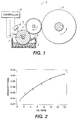
- FIG. 1 an oil application system 1 is shown where a fuser roller 2 is being coated with oil.
- a source oil from oil housing 3 is in flow contact with a metering roller 4.
- the metering roller 4 deposits the oil 7 to a donor roller 5; from there the donor roller 5 deposits an oil film upon the surface of fuser roller 2.
- the donor roller 5 has an outside surface comprising Viton®.
- Viton® is a trademark of DuPont.
- Viton® fluoroelastomer is the most preferred fluoroelastomer, well known for its excellent (400 degree F/200 degree C) heat resistance. Viton® offers excellent resistance to aggressive fuels and chemicals and has worldwide ISO 9000 and ISO/TS 16949 registration.
- An IR sensor 6 measures the emissivity of the oil on the surface of metering roller 4. Since the amount of oil on the surface of metering roller 4 is directly proportional to the emissivity of the oil layer, it is easy to control the rate of the oil deposited on the metering roller 4 by controlling this emissivity.
- a pressure roller is not shown in Figure 1 , but it is understood that the pressure roller is in contact at any location with the fuser roller 2. For clarity, the pressure roller is not shown.
- a controller 8 is in electrical connection with the IR sensor 6 to control the flow of oil 7 to the metering roller 4.
- Figure 1 shows the basic diagram of an embodiment of the roller oil application system 1 herein described.
- the metering roller 4 is normally heated in order to make the viscosity of the oil 7 less variable due to warm up and running transients.
- Bare metal rollers usually have low IR emissivity, on the order of 0.05 to 0.20. That means at a given temperature, metal rollers emit 5 to 20% of the infrared radiation that a black body radiator would at the same temperature.
- polymers such as silicone oil 7 have high emissivity, often in the range of 0.85 to 0.95. As a result, as the metering roller 4 gets coated with silicone oil 7, its apparent emissivity will increase.
- silicone thickness f(IR, metering roller temp) is probably best determined empirically but an estimate can be generated using first principles. Also, sensitivity may be enhanced by windowing the IR sensor 6 between specific wavelengths. Now that an effective silicone thickness sensor 6 is available, it can be used for closed loop process control of the oil rate. In this example, the metering roller 4 speed can be used to adjust the film thickness (the faster the speed, the higher the thickness past the doctor blade 9). The sensor 6 output can then be used to vary the metering roller 4 speed to control the oil film thickness.
- the oil rate that is applied to the fuser is directly proportional to the oil film on the metering roller 4 after the donor roller 5 nip. By monitoring the oil film thickness here, one can know and control the amount of oil application to the fuser roller 2 and hence the media.
- the metering roller 4 is chrome plated and has a very low IR emissivity in the wavelengths of interest between 1 and 20 um. Also during release agent management (RAM) operation the metering roller 4 is heated to approximately 145° C. This is convenient because the metering roller 4 will self emit IR so the measuring system can be passive without the need for active controlled IR illumination.
- a variable speed metering roller RAM system was installed in a xerographic marking system. Oil rate is then adjustable by changing the rotational speed of the metering roller relative to the donor roller.
- An IR temperature sensor such as Omega Engineering OS36-J model was installed so that the metering roller surface temperature is measured after the metering roller/donor roller nip. The oil film thickness at this point indicates the amount of oil that was transferred to the donor roller and ultimately the fuser roller.
- the metering roller is controlled at a constant temperature of about 142° C. This was verified by reading the process control thermistor on the roller. Oil rate was presumptively varied and print samples were taken to measure the actual oil on the prints corresponding to the test condition. Six metering roller speeds were run and the oil rate and indicated temperature of the metering roller was measured by the IR probe. The effective emissivity of the metering roller was calculated.
- the desired oil rate can be achieved by controlling the specific oil rate corresponding to the emissivity measured.
- the IR sensor is electrically connected to a controller that is configured to receive emissivity information from the IR sensor ad enabled to thereafter control a flow rate or dispensing of the oil to the donor roller based upon said emissivity.
- the emissivity of a material is the rate of thermal energy radiated by the material to energy radiated by a black body at the same temperature per unit area.
- the corresponding emissivity can be set to provide that oil rate.
- this invention provides an oil application system useful in applying an oil coating to a fuser roller in a xerographic marking system.
- This system comprises a fuser roller, an oil containing housing or reservoir, a metering roller, a donor roller, an IR sensor, and a controller connected to said IP sensor.
- the metering roller and the donor roller are positioned between the fuser roller and the oil containing housing.
- the IR sensor is positioned adjacent the metering roller and is configured to measure an emissivity of an oil coating on the metering roller.
- the metering roller is configured to transport oil from the oil housing to the donor roller.
- the donor roller is configured to accept an oil coating from the metering roller and to transfer the oil to a surface of the fuser roller.
- the IR sensor is electrically connected to a controller which is configured to receive emissivity information from the IR sensor and is configured to thereafter control a flow rate or dispensing of the oil to the donor roller based upon the indicated emissivity.
- the metering roller has positioned a doctor blade in contact with its surface at a location after contact of the metering roller with the donor roller.
- the donor roller has an outside surface comprising Viton.
- the metering roller comprises a heater. This heater is capable of controlling a viscosity of the oil.
- this system comprises a fuser roller, an oil containing housing or reservoir, a metering roller, a donor roller, and an IR sensor, and a controller connected to the IP sensor.
- the metering roller and the donor roller are positioned between the fuser roller and the oil housing.
- the IR sensor is positioned adjacent the metering roller and is configured to measure an emissivity of an oil coating on the metering roller.
- This IR sensor is configured to indicate increased IR radiation as said oil film or coating thickness increases and vice-versa as the oil film thickness decreases.
- the IR sensor and the controller together are configured to vary the metering roller speed to thereby control the oil film thickness based upon emissivity of the oil film.
- the IR sensor is configured to measure emissivity of the oil coating on the metering roller, and configured to communicate this emissivity to the controller.
- the controller is in contact with the metering roller and is adapted to adjust the film thickness on the metering roller.
- the IR sensor is electrically connected to a controller which is configured to receive emissivity information from the IR sensor and configured to thereafter control a flow rate or dispensing of the oil to the donor roller based upon said emissivity.
Landscapes
- Physics & Mathematics (AREA)
- General Physics & Mathematics (AREA)
- Fixing For Electrophotography (AREA)
- Cleaning In Electrography (AREA)
- Coating Apparatus (AREA)
- Application Of Or Painting With Fluid Materials (AREA)
Claims (4)
- System zum Auftragen von Öl, das beim Auftragen einer Ölbeschichtung auf eine Fixier-walze (2) in einem xerographischen Drucksystem eingesetzt werden kann, wobei das System umfasst:eine Fixierwalze (2),ein Gehäuse oder einen Vorratsbehälter (3) zum Aufnehmen von Öl,eine Dosierwalze (4),eine Abgabewalze (5),wobei die Dosierwalze (4) so eingerichtet ist, dass sie Öl von dem Gehäuse zu der Abgabewalze (5) transportiert, unddie Abgabewalze (5) so eingerichtet ist, dass sie eine Ölbeschichtung von der Dosierwalze (4) aufnimmt und das Öl auf eine Oberfläche der Fixierwalze überträgt,
gekennzeichnet durcheinen IR-Sensor (6) sowie eine Steuereinrichtung, die mit dem IR-Sensor (6) verbunden ist,wobei der IR-Sensor (6) an die Dosierwalze (4) angrenzend angeordnet und so eingerichtet ist, dass er ein Emissionsvermögen einer Ölbeschichtung auf der Dosierwalze (4) misst,der IR-Sensor (6) so eingerichtet ist, dass er erhöhte IR-Strahlung anzeigt, wenn eine Dicke der Ölbeschichtung zunimmt, und umgekehrt, wenn die Dicke der Ölbeschichtung abnimmt, und so eingerichtet ist, dass er das Emissionsvermögen zu der Steuereinrichtung überträgt,der IR-Sensor (6) und die Steuereinrichtung zusammen so eingerichtet sind, dass sie eine Geschwindigkeit der Dosierwalze (4) ändern, um so die Dicke der Ölbeschichtung auf Basis des Emissionsvermögens der Ölbeschichtung zu steuern,die Steuereinrichtung in Kontakt mit der Dosierwalze (4) ist und so eingerichtet ist, dass sie die Beschichtungsdicke auf der Dosierwalze (4) reguliert. - System nach Anspruch 1, wobei eine Rakel an einer Stelle nach Kontakt der Dosierwalze (4) mit der Abgabewalze (5) mit der Oberfläche der Dosierwalze (4) in Kontakt ist.
- System nach Anspruch 1, wobei die Abgabewalze (5) eine Außenfläche hat, die Viton® umfasst.
- System nach Anspruch 1, wobei die Dosierwalze (4) eine Heizeinrichtung umfasst und die Heizeinrichtung eine Viskosität des Öls steuern kann.
Applications Claiming Priority (1)
| Application Number | Priority Date | Filing Date | Title |
|---|---|---|---|
| US12/352,136 US8126382B2 (en) | 2009-01-12 | 2009-01-12 | Passive IR oil rate sensor |
Publications (2)
| Publication Number | Publication Date |
|---|---|
| EP2207066A1 EP2207066A1 (de) | 2010-07-14 |
| EP2207066B1 true EP2207066B1 (de) | 2016-03-30 |
Family
ID=42101585
Family Applications (1)
| Application Number | Title | Priority Date | Filing Date |
|---|---|---|---|
| EP10150544.4A Not-in-force EP2207066B1 (de) | 2009-01-12 | 2010-01-12 | Passiver IR-Öldurchflussmesser |
Country Status (3)
| Country | Link |
|---|---|
| US (1) | US8126382B2 (de) |
| EP (1) | EP2207066B1 (de) |
| JP (1) | JP5385162B2 (de) |
Families Citing this family (4)
| Publication number | Priority date | Publication date | Assignee | Title |
|---|---|---|---|---|
| US8899738B2 (en) * | 2013-01-21 | 2014-12-02 | Xerox Corporation | Pressure roller containing a volume of fluid |
| US9022548B2 (en) | 2013-07-16 | 2015-05-05 | Xerox Corporation | System and method for monitoring the application of release agent in an inkjet printer |
| US9056464B2 (en) | 2013-07-16 | 2015-06-16 | Xerox Corporation | System and method for optimized application of release agent in an inkjet printer with in-line coating |
| DE102022105829A1 (de) * | 2021-04-16 | 2022-10-20 | Heidelberger Druckmaschinen Aktiengesellschaft | Betriebsverfahren für ein Lackierwerk einer Druckmaschine |
Citations (2)
| Publication number | Priority date | Publication date | Assignee | Title |
|---|---|---|---|---|
| EP0455470A2 (de) * | 1990-04-30 | 1991-11-06 | Xerox Corporation | Schmelzfixiereinheit mit Trennmittelabgabeelement |
| JPH03249684A (ja) * | 1990-02-28 | 1991-11-07 | Fujitsu Ltd | 熱定着器 |
Family Cites Families (11)
| Publication number | Priority date | Publication date | Assignee | Title |
|---|---|---|---|---|
| US4193681A (en) | 1977-06-30 | 1980-03-18 | Canon Kabushiki Kaisha | Liquid feeding device |
| JPH0273388A (ja) | 1988-09-09 | 1990-03-13 | Hitachi Koki Co Ltd | 電子写真式印刷装置のオイル供給制御方法 |
| US5819148A (en) * | 1997-10-30 | 1998-10-06 | Xerox Corporation | Renewable thin film oil metering blade |
| US6263182B1 (en) * | 2000-05-09 | 2001-07-17 | Lexmark International, Inc. | Fuser oil dispenser for an image forming apparatus |
| JP2002229369A (ja) * | 2001-01-31 | 2002-08-14 | Ricoh Co Ltd | 定着装置 |
| JP2004117203A (ja) * | 2002-09-26 | 2004-04-15 | Toyota Motor Corp | 非接触温度計測装置 |
| JP2005188994A (ja) * | 2003-12-24 | 2005-07-14 | Toyota Motor Corp | 金型上の塗布剤の膜厚測定方法及び金型上の塗布剤の塗布量制御方法 |
| US7214462B2 (en) * | 2004-06-25 | 2007-05-08 | Xerox Corporation | Blended amino functional siloxane release agents for fuser members |
| US7376378B2 (en) * | 2005-04-25 | 2008-05-20 | Xerox Corporation | Method and system for improved metering of release agent in an electrophotographic system |
| JP2007058021A (ja) * | 2005-08-26 | 2007-03-08 | Fuji Xerox Co Ltd | 画像形成装置 |
| JP5194618B2 (ja) * | 2007-08-01 | 2013-05-08 | 株式会社リコー | 離型剤塗布装置及びそれを有する定着装置 |
-
2009
- 2009-01-12 US US12/352,136 patent/US8126382B2/en not_active Expired - Fee Related
-
2010
- 2010-01-06 JP JP2010001223A patent/JP5385162B2/ja not_active Expired - Fee Related
- 2010-01-12 EP EP10150544.4A patent/EP2207066B1/de not_active Not-in-force
Patent Citations (2)
| Publication number | Priority date | Publication date | Assignee | Title |
|---|---|---|---|---|
| JPH03249684A (ja) * | 1990-02-28 | 1991-11-07 | Fujitsu Ltd | 熱定着器 |
| EP0455470A2 (de) * | 1990-04-30 | 1991-11-06 | Xerox Corporation | Schmelzfixiereinheit mit Trennmittelabgabeelement |
Also Published As
| Publication number | Publication date |
|---|---|
| JP2010160485A (ja) | 2010-07-22 |
| US8126382B2 (en) | 2012-02-28 |
| US20100178087A1 (en) | 2010-07-15 |
| EP2207066A1 (de) | 2010-07-14 |
| JP5385162B2 (ja) | 2014-01-08 |
Similar Documents
| Publication | Publication Date | Title |
|---|---|---|
| US6763205B2 (en) | Image heating apparatus with heater in form of a plate cooperable with a rotatable member to form a heating nip | |
| US9329535B2 (en) | Image heating apparatus | |
| EP1780608B1 (de) | Fixiervorrichtung für ein Nichtheizfixiersystem | |
| CN104885017B (zh) | 用于基于定影器部件属性控制定影器操作的定影器组件及方法 | |
| US8126382B2 (en) | Passive IR oil rate sensor | |
| US7362994B2 (en) | Release agent application apparatus and method | |
| US9835974B2 (en) | Method and developer station for adaptation of the inking of an image substrate of a toner-based digital printer | |
| US20030210934A1 (en) | Fixing mechanism for use in image forming apparatus | |
| US5839041A (en) | RAM system including a bidirectional metering member and a dual purpose swiper blade | |
| JP5196804B2 (ja) | 像加熱装置 | |
| JP5285241B2 (ja) | 画像形成装置 | |
| US7046948B1 (en) | Brush streak eraser | |
| US5943542A (en) | Dual levels of functional and non-reactive release agents for fusers | |
| US10452010B2 (en) | Fuser temperature control in an imaging device | |
| US5875381A (en) | Release agent applied to fuser roll via paper | |
| JPH06138788A (ja) | 定着装置及び画像形成装置並びに電子写真用フィルム | |
| US20170031259A1 (en) | Method and device for improving the toner transfer in an electrographic digital printer | |
| US20060193661A1 (en) | Roll fuser apparatus | |
| US3884181A (en) | Capillary baffle-constant oil height independent of oil level | |
| JP2008242335A (ja) | 画像形成装置 | |
| US9753418B2 (en) | Fixing apparatus for fixing a toner image on a recording medium while conveying and heating the recording medium | |
| JP2001075417A (ja) | 画像形成装置 | |
| JP2019066594A (ja) | 定着装置および画像形成装置 | |
| EP3762788B1 (de) | Identifizierung und behebung von tuchkriechverhalten | |
| US5819148A (en) | Renewable thin film oil metering blade |
Legal Events
| Date | Code | Title | Description |
|---|---|---|---|
| PUAI | Public reference made under article 153(3) epc to a published international application that has entered the european phase |
Free format text: ORIGINAL CODE: 0009012 |
|
| AK | Designated contracting states |
Kind code of ref document: A1 Designated state(s): AT BE BG CH CY CZ DE DK EE ES FI FR GB GR HR HU IE IS IT LI LT LU LV MC MK MT NL NO PL PT RO SE SI SK SM TR |
|
| AX | Request for extension of the european patent |
Extension state: AL BA RS |
|
| 17P | Request for examination filed |
Effective date: 20110114 |
|
| 17Q | First examination report despatched |
Effective date: 20150504 |
|
| GRAP | Despatch of communication of intention to grant a patent |
Free format text: ORIGINAL CODE: EPIDOSNIGR1 |
|
| INTG | Intention to grant announced |
Effective date: 20151002 |
|
| GRAS | Grant fee paid |
Free format text: ORIGINAL CODE: EPIDOSNIGR3 |
|
| GRAA | (expected) grant |
Free format text: ORIGINAL CODE: 0009210 |
|
| AK | Designated contracting states |
Kind code of ref document: B1 Designated state(s): AT BE BG CH CY CZ DE DK EE ES FI FR GB GR HR HU IE IS IT LI LT LU LV MC MK MT NL NO PL PT RO SE SI SK SM TR |
|
| REG | Reference to a national code |
Ref country code: GB Ref legal event code: FG4D |
|
| REG | Reference to a national code |
Ref country code: CH Ref legal event code: EP |
|
| REG | Reference to a national code |
Ref country code: AT Ref legal event code: REF Ref document number: 786008 Country of ref document: AT Kind code of ref document: T Effective date: 20160415 |
|
| REG | Reference to a national code |
Ref country code: IE Ref legal event code: FG4D |
|
| REG | Reference to a national code |
Ref country code: DE Ref legal event code: R096 Ref document number: 602010031560 Country of ref document: DE |
|
| REG | Reference to a national code |
Ref country code: LT Ref legal event code: MG4D |
|
| PG25 | Lapsed in a contracting state [announced via postgrant information from national office to epo] |
Ref country code: GR Free format text: LAPSE BECAUSE OF FAILURE TO SUBMIT A TRANSLATION OF THE DESCRIPTION OR TO PAY THE FEE WITHIN THE PRESCRIBED TIME-LIMIT Effective date: 20160701 Ref country code: NO Free format text: LAPSE BECAUSE OF FAILURE TO SUBMIT A TRANSLATION OF THE DESCRIPTION OR TO PAY THE FEE WITHIN THE PRESCRIBED TIME-LIMIT Effective date: 20160630 Ref country code: FI Free format text: LAPSE BECAUSE OF FAILURE TO SUBMIT A TRANSLATION OF THE DESCRIPTION OR TO PAY THE FEE WITHIN THE PRESCRIBED TIME-LIMIT Effective date: 20160330 Ref country code: HR Free format text: LAPSE BECAUSE OF FAILURE TO SUBMIT A TRANSLATION OF THE DESCRIPTION OR TO PAY THE FEE WITHIN THE PRESCRIBED TIME-LIMIT Effective date: 20160330 |
|
| REG | Reference to a national code |
Ref country code: NL Ref legal event code: MP Effective date: 20160330 |
|
| REG | Reference to a national code |
Ref country code: AT Ref legal event code: MK05 Ref document number: 786008 Country of ref document: AT Kind code of ref document: T Effective date: 20160330 |
|
| PG25 | Lapsed in a contracting state [announced via postgrant information from national office to epo] |
Ref country code: LV Free format text: LAPSE BECAUSE OF FAILURE TO SUBMIT A TRANSLATION OF THE DESCRIPTION OR TO PAY THE FEE WITHIN THE PRESCRIBED TIME-LIMIT Effective date: 20160330 Ref country code: LT Free format text: LAPSE BECAUSE OF FAILURE TO SUBMIT A TRANSLATION OF THE DESCRIPTION OR TO PAY THE FEE WITHIN THE PRESCRIBED TIME-LIMIT Effective date: 20160330 Ref country code: SE Free format text: LAPSE BECAUSE OF FAILURE TO SUBMIT A TRANSLATION OF THE DESCRIPTION OR TO PAY THE FEE WITHIN THE PRESCRIBED TIME-LIMIT Effective date: 20160330 |
|
| PG25 | Lapsed in a contracting state [announced via postgrant information from national office to epo] |
Ref country code: NL Free format text: LAPSE BECAUSE OF FAILURE TO SUBMIT A TRANSLATION OF THE DESCRIPTION OR TO PAY THE FEE WITHIN THE PRESCRIBED TIME-LIMIT Effective date: 20160330 |
|
| PG25 | Lapsed in a contracting state [announced via postgrant information from national office to epo] |
Ref country code: IS Free format text: LAPSE BECAUSE OF FAILURE TO SUBMIT A TRANSLATION OF THE DESCRIPTION OR TO PAY THE FEE WITHIN THE PRESCRIBED TIME-LIMIT Effective date: 20160730 Ref country code: PL Free format text: LAPSE BECAUSE OF FAILURE TO SUBMIT A TRANSLATION OF THE DESCRIPTION OR TO PAY THE FEE WITHIN THE PRESCRIBED TIME-LIMIT Effective date: 20160330 Ref country code: EE Free format text: LAPSE BECAUSE OF FAILURE TO SUBMIT A TRANSLATION OF THE DESCRIPTION OR TO PAY THE FEE WITHIN THE PRESCRIBED TIME-LIMIT Effective date: 20160330 |
|
| PG25 | Lapsed in a contracting state [announced via postgrant information from national office to epo] |
Ref country code: RO Free format text: LAPSE BECAUSE OF FAILURE TO SUBMIT A TRANSLATION OF THE DESCRIPTION OR TO PAY THE FEE WITHIN THE PRESCRIBED TIME-LIMIT Effective date: 20160330 Ref country code: CZ Free format text: LAPSE BECAUSE OF FAILURE TO SUBMIT A TRANSLATION OF THE DESCRIPTION OR TO PAY THE FEE WITHIN THE PRESCRIBED TIME-LIMIT Effective date: 20160330 Ref country code: SK Free format text: LAPSE BECAUSE OF FAILURE TO SUBMIT A TRANSLATION OF THE DESCRIPTION OR TO PAY THE FEE WITHIN THE PRESCRIBED TIME-LIMIT Effective date: 20160330 Ref country code: SM Free format text: LAPSE BECAUSE OF FAILURE TO SUBMIT A TRANSLATION OF THE DESCRIPTION OR TO PAY THE FEE WITHIN THE PRESCRIBED TIME-LIMIT Effective date: 20160330 Ref country code: ES Free format text: LAPSE BECAUSE OF FAILURE TO SUBMIT A TRANSLATION OF THE DESCRIPTION OR TO PAY THE FEE WITHIN THE PRESCRIBED TIME-LIMIT Effective date: 20160330 Ref country code: PT Free format text: LAPSE BECAUSE OF FAILURE TO SUBMIT A TRANSLATION OF THE DESCRIPTION OR TO PAY THE FEE WITHIN THE PRESCRIBED TIME-LIMIT Effective date: 20160801 Ref country code: AT Free format text: LAPSE BECAUSE OF FAILURE TO SUBMIT A TRANSLATION OF THE DESCRIPTION OR TO PAY THE FEE WITHIN THE PRESCRIBED TIME-LIMIT Effective date: 20160330 |
|
| REG | Reference to a national code |
Ref country code: FR Ref legal event code: PLFP Year of fee payment: 8 |
|
| PG25 | Lapsed in a contracting state [announced via postgrant information from national office to epo] |
Ref country code: IT Free format text: LAPSE BECAUSE OF FAILURE TO SUBMIT A TRANSLATION OF THE DESCRIPTION OR TO PAY THE FEE WITHIN THE PRESCRIBED TIME-LIMIT Effective date: 20160330 Ref country code: BE Free format text: LAPSE BECAUSE OF FAILURE TO SUBMIT A TRANSLATION OF THE DESCRIPTION OR TO PAY THE FEE WITHIN THE PRESCRIBED TIME-LIMIT Effective date: 20160330 |
|
| REG | Reference to a national code |
Ref country code: DE Ref legal event code: R097 Ref document number: 602010031560 Country of ref document: DE |
|
| PG25 | Lapsed in a contracting state [announced via postgrant information from national office to epo] |
Ref country code: DK Free format text: LAPSE BECAUSE OF FAILURE TO SUBMIT A TRANSLATION OF THE DESCRIPTION OR TO PAY THE FEE WITHIN THE PRESCRIBED TIME-LIMIT Effective date: 20160330 |
|
| PLBE | No opposition filed within time limit |
Free format text: ORIGINAL CODE: 0009261 |
|
| STAA | Information on the status of an ep patent application or granted ep patent |
Free format text: STATUS: NO OPPOSITION FILED WITHIN TIME LIMIT |
|
| 26N | No opposition filed |
Effective date: 20170103 |
|
| PG25 | Lapsed in a contracting state [announced via postgrant information from national office to epo] |
Ref country code: SI Free format text: LAPSE BECAUSE OF FAILURE TO SUBMIT A TRANSLATION OF THE DESCRIPTION OR TO PAY THE FEE WITHIN THE PRESCRIBED TIME-LIMIT Effective date: 20160330 |
|
| REG | Reference to a national code |
Ref country code: CH Ref legal event code: PL |
|
| PG25 | Lapsed in a contracting state [announced via postgrant information from national office to epo] |
Ref country code: MC Free format text: LAPSE BECAUSE OF FAILURE TO SUBMIT A TRANSLATION OF THE DESCRIPTION OR TO PAY THE FEE WITHIN THE PRESCRIBED TIME-LIMIT Effective date: 20160330 |
|
| PG25 | Lapsed in a contracting state [announced via postgrant information from national office to epo] |
Ref country code: CH Free format text: LAPSE BECAUSE OF NON-PAYMENT OF DUE FEES Effective date: 20170131 Ref country code: LI Free format text: LAPSE BECAUSE OF NON-PAYMENT OF DUE FEES Effective date: 20170131 |
|
| REG | Reference to a national code |
Ref country code: IE Ref legal event code: MM4A |
|
| PG25 | Lapsed in a contracting state [announced via postgrant information from national office to epo] |
Ref country code: LU Free format text: LAPSE BECAUSE OF NON-PAYMENT OF DUE FEES Effective date: 20170112 |
|
| REG | Reference to a national code |
Ref country code: FR Ref legal event code: PLFP Year of fee payment: 9 |
|
| PGFP | Annual fee paid to national office [announced via postgrant information from national office to epo] |
Ref country code: FR Payment date: 20171221 Year of fee payment: 9 |
|
| PG25 | Lapsed in a contracting state [announced via postgrant information from national office to epo] |
Ref country code: IE Free format text: LAPSE BECAUSE OF NON-PAYMENT OF DUE FEES Effective date: 20170112 |
|
| PGFP | Annual fee paid to national office [announced via postgrant information from national office to epo] |
Ref country code: GB Payment date: 20171222 Year of fee payment: 9 |
|
| PGFP | Annual fee paid to national office [announced via postgrant information from national office to epo] |
Ref country code: DE Payment date: 20171218 Year of fee payment: 9 |
|
| PG25 | Lapsed in a contracting state [announced via postgrant information from national office to epo] |
Ref country code: MT Free format text: LAPSE BECAUSE OF NON-PAYMENT OF DUE FEES Effective date: 20170112 |
|
| PG25 | Lapsed in a contracting state [announced via postgrant information from national office to epo] |
Ref country code: HU Free format text: LAPSE BECAUSE OF FAILURE TO SUBMIT A TRANSLATION OF THE DESCRIPTION OR TO PAY THE FEE WITHIN THE PRESCRIBED TIME-LIMIT; INVALID AB INITIO Effective date: 20100112 |
|
| REG | Reference to a national code |
Ref country code: DE Ref legal event code: R119 Ref document number: 602010031560 Country of ref document: DE |
|
| PG25 | Lapsed in a contracting state [announced via postgrant information from national office to epo] |
Ref country code: BG Free format text: LAPSE BECAUSE OF FAILURE TO SUBMIT A TRANSLATION OF THE DESCRIPTION OR TO PAY THE FEE WITHIN THE PRESCRIBED TIME-LIMIT Effective date: 20160330 |
|
| GBPC | Gb: european patent ceased through non-payment of renewal fee |
Effective date: 20190112 |
|
| PG25 | Lapsed in a contracting state [announced via postgrant information from national office to epo] |
Ref country code: CY Free format text: LAPSE BECAUSE OF NON-PAYMENT OF DUE FEES Effective date: 20160330 Ref country code: DE Free format text: LAPSE BECAUSE OF NON-PAYMENT OF DUE FEES Effective date: 20190801 Ref country code: FR Free format text: LAPSE BECAUSE OF NON-PAYMENT OF DUE FEES Effective date: 20190131 |
|
| PG25 | Lapsed in a contracting state [announced via postgrant information from national office to epo] |
Ref country code: MK Free format text: LAPSE BECAUSE OF FAILURE TO SUBMIT A TRANSLATION OF THE DESCRIPTION OR TO PAY THE FEE WITHIN THE PRESCRIBED TIME-LIMIT Effective date: 20160330 |
|
| PG25 | Lapsed in a contracting state [announced via postgrant information from national office to epo] |
Ref country code: GB Free format text: LAPSE BECAUSE OF NON-PAYMENT OF DUE FEES Effective date: 20190112 |
|
| PG25 | Lapsed in a contracting state [announced via postgrant information from national office to epo] |
Ref country code: TR Free format text: LAPSE BECAUSE OF FAILURE TO SUBMIT A TRANSLATION OF THE DESCRIPTION OR TO PAY THE FEE WITHIN THE PRESCRIBED TIME-LIMIT Effective date: 20160330 |