EP2208432A1 - Récipient et coffre - Google Patents
Récipient et coffre Download PDFInfo
- Publication number
- EP2208432A1 EP2208432A1 EP09015156A EP09015156A EP2208432A1 EP 2208432 A1 EP2208432 A1 EP 2208432A1 EP 09015156 A EP09015156 A EP 09015156A EP 09015156 A EP09015156 A EP 09015156A EP 2208432 A1 EP2208432 A1 EP 2208432A1
- Authority
- EP
- European Patent Office
- Prior art keywords
- groove
- edge
- wall
- edge frame
- side wall
- Prior art date
- Legal status (The legal status is an assumption and is not a legal conclusion. Google has not performed a legal analysis and makes no representation as to the accuracy of the status listed.)
- Withdrawn
Links
Images
Classifications
-
- A—HUMAN NECESSITIES
- A45—HAND OR TRAVELLING ARTICLES
- A45C—PURSES; LUGGAGE; HAND CARRIED BAGS
- A45C5/00—Rigid or semi-rigid luggage
- A45C5/02—Materials therefor
-
- A—HUMAN NECESSITIES
- A45—HAND OR TRAVELLING ARTICLES
- A45C—PURSES; LUGGAGE; HAND CARRIED BAGS
- A45C5/00—Rigid or semi-rigid luggage
- A45C5/03—Suitcases
- A45C2005/037—Suitcases with a hard shell, i.e. rigid shell as volume creating element
Definitions
- the invention relates to a container comprising a polygonal wall element of a plurality of vertical side walls integrally connected to one another via corner regions, each side wall having at least one edge which extends into a main groove of an edge frame element and is latched thereto by at least one engages from the wall surface of the side wall projecting locking projection into a side groove in one of the groove walls of the main groove, wherein the side groove extends over the entire length of the edge frame element.
- the invention further relates to a suitcase comprising two case shells interconnected by means of one or more hinges.
- Each such container represents one of two case shells of a suitcase, which are hinged together via one or more hinges. When closed each serves as an edge frame as a fixing base of the hinges and as a contact surface on the other case shell.
- generic containers individually, ie as coverless boxes, the edge frames in this case forming the upper edge termination of the box.
- the edge frames are each formed in one piece, i.
- Each edge frame consists of exactly one edge frame element, which is designed like a frame.
- the edge frame is fitted accurately on the upper edges of all side walls and corner areas, so that the edges between the groove walls of the main groove, which runs through the entire edge frame open down, can slide into it.
- On the inside of the case shell a locking strip is provided, which is angled downwards inwardly connected to the side walls and the entire case shell rings around.
- the locking strip is elastically bent down to spring at a sufficiently deep slot in a side groove in the inner groove wall of the main groove of the edge frame.
- the edge frame is permanently connected to the side walls. He can not be non-destructive, i. especially not without breaking the locking bar to be separated from the case shell.
- the tabs are produced by a stamping process in which the wall material is severed at three edges of the tab.
- the tabs To be able to act as a latching projection, the tabs must be issued manually before the connection with the edge frame. It must not come at the bend line to a sharp, breaking the fibers kink, otherwise the stability of the detent would be weakened. Without such a kink, however, results in a permanent restoring force that tries to pull the tabs in their original position, namely parallel to the side walls. Therefore, it may happen that when upsetting the wall material, for example, too heavy loading or hard placement of a loaded box, the tabs can be released from the frame profile and the edge frame can be separated from the side walls.
- From the DE 199 007 18 A1 is a box of a cage-like frame, which comprises an upper and a lower edge frame and this connecting corner posts known.
- the wall surfaces are covered with wall sheets, which are glued or welded to the cage-like frame.
- the edge frames are each formed from straight individual profiles which are connected to each other via angle elements. For this purpose, the angle elements are plugged onto the corner posts and have lateral recesses into which the ends of the straight individual profiles are inserted.
- latching projection is formed as a generated by a punching step, plastic deformation of the sidewall material, wherein at least in the region of the side edges of the latching projection, the sidewall material is un mictrennt.
- Such containers are preferably used as one of two case shells connected to one another via one or more hinges, wherein the containers bear against one another with their edge frame elements in the closed state of the case.
- the wall material is substantially imperforate and essentially only a plastic deformation on a small surface during the punching process, but at comparatively many points.
- Typical distances of the locking gills thus produced are in the range between 1 and 5 centimeters.
- Distributed over the length of a suitcase shell can be provided 5 to 10 or more locking gills.
- the punching tool used for this purpose can be a short, the rear edge of the belt defining cutting edge and a perpendicular to the cutting edge extension, have bevelled stamp.
- the wall material at the rear edge of the gill is weakened by a cut which preferably does not completely cut through the material.
- the material is deformed by means of the adjoining the punch stamp, so that there is a bulge on the opposite side of the punching tool, which decreases from the rear edge of the gill to the front edge of the gill.
- the side edges of the gills remain connected via gusset-shaped side portions with the remaining wall material in combination.
- the gusset-like side areas stabilize the flared gill and counteract a possible restoring force, which may be due to elastic material properties.
- a permanently stable latching projection is created in a very small space, which can be created in a simple punching step.
- the side walls of the container can thus be manufactured on injection molding technology very simple way with simply designed tools. All locking gills of a side wall can be produced in a simultaneous punching step.
- edge frame elements In order to simplify the production of the edge frame is provided in a development of the invention that a number of side walls corresponding plurality of designed as a straight rails edge frame elements are connected to a rim frame, wherein the ends of each rail in corresponding recesses of angle elements, the rounded corner areas are fitted, are plugged.
- the profile strips are inserted with axial clearance in the recesses of the angle elements.
- the side walls of the polygonal wall element are connected at their edges facing away from the frame elements via a tub-like bottom element.
- a tub-like bottom element Preferably, it is also possible to make the polygonal wall element open on both sides, and to provide at the top and bottom according to the invention with a border frame. Cover surfaces may then be attached in any suitable manner.
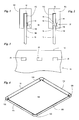
- FIGS. 1 to 3 show details of a side wall 10 of a container according to the invention. While FIG. 3 schematically shows a side view of a section of the side wall 10, are the Figures 1 and 2 schematic sectional views through different areas of a side wall 10, on which an edge frame member 110 is placed and locked. As in FIG. 3 recognizable, the side wall 10 is provided near its upper edge 12 with a bar stamped Rastkiemen 20.
- FIG. 1 shows a sectional view in a region between two latching gills 20;
- FIG. 2 shows a sectional view in the region of a locking gill 20. The figures will be discussed together below.
- the side wall which is preferably made of hard plastic or metal, in particular aluminum, represents a substantially flat wall with upper edge 12.
- the lower edge of the side wall 10 is not shown in the figures. It is preferred that the lower edges of all side walls of the container integrally merge into a common floor pan.
- the formation of a locking gill 20 preferably without complete transection of the wall material of the side wall 10. Rather, the lower edge of the locking gill 20 is defined by a wall material not completely penetrating section 14.
- the cut 14 is caused during a punching operation by a narrow cutting edge, at the broad side of which a punch adjoins, which bulges the weakened by the cut 14 wall material to the opposite wall side.
- a recess 16 is formed, which increases from an upper edge of the locking gill 20 determined by the dimensions of the punching punch up to the cut 14.
- On the opposite side creates a plastically deformed bulge 19, which has its largest dimensions immediately above the cut 14.
- the bulge 19 has a comparatively sharp lower edge and a flat course upwards.
- a normal to the wall surface directed force component on the bulge 19 leads to an elastic deformation, in which the recess 16 is reduced.
- the bulge 19 returns to a relief of the said force component in their in the Figures 1 and 2 shown position back. This is used according to the invention for locking the edge frame element 110.
- the edge frame element 110 has a central main groove 112, whose groove width corresponds approximately to the wall thickness of the side wall 10, ie, is slightly larger, so that the side wall 10 can be inserted into the main groove 112.
- the lower edge 114 of the main groove exerts a force on the locking gill 20.
- This force contains a normal component which forces the bulge 19 to elastically spring in the above-described manner.
- At least one of the side walls of the main groove has a side groove 116 whose dimensions are adapted to the dimensions of the bulge 19.
- the groove depth of the side groove 116 is at least as large as the protrusion of the bulge 16 over the surface of the side wall 10.
- the groove width of the side groove 116 should be wide enough to accommodate the buckle 19 at least to a substantial extent.
- the side wall 10 Due to the sharp lower edge of the bulge 19, the side wall 10 is held in the detent position. In particular, a downward pull on the side wall 10 substantially results in forces on the bulge 19 directed tangentially to the side wall 10. These tangential forces can not force compression of the bulge 19. For this purpose, as described above, a normal force component would be required, which can not or only negligibly occur due to the sharp lower edge of the bulge 19.
- the edge frame element 110 is thus permanently connected to the side wall 10.
- a further advance of the side wall 10, ie a deeper penetration into the main groove 112 is prevented by appropriate relative dimensioning.
- the distance of the side groove from the groove bottom of the main groove should be approximately the distance of the locking gill 20 from the upper edge 12 of the side wall 10th corresponding.
- the connection is completely sealed.
- the gap between the side wall 10 and the main groove 112 is realized by the elastic sealing element; the locking gills are also no leakage points, as they preferably at no point a complete material separation of the sidewall material show.
- FIG. 4 shows an edge frame 100, consisting of 4 edge frame elements 110, which are connected to each other via angle elements 120.
- the angle elements have lateral recesses into which the edge frame elements, which are designed as straight profiled rails, are inserted. This is preferably done with an axial play, which is sufficiently large to compensate for manufacturing tolerances of the side walls 10 and the profile rails 110.
- the profile rails 110 are preferably made of hard plastic or metal, in particular aluminum.
- the side walls 10 are formed of hard plastic, the profile rails 110 of aluminum and the angle elements of a stable, more elastic plastic than the side walls.
- the angle elements 120 preferably have grooves which connect the main grooves 112 of the profile rails 110 in the corner regions, via the side walls 10 are, extend.
- the corner regions are preferably formed rounded.
- the groove width of the main groove 112 should not be too small, since it is possible, in particular with thin side walls 10, that they have a certain waviness, so that edge frames with a wider main groove are easier to assemble.
Landscapes
- Chemical & Material Sciences (AREA)
- Engineering & Computer Science (AREA)
- Materials Engineering (AREA)
- Rigid Containers With Two Or More Constituent Elements (AREA)
Applications Claiming Priority (1)
| Application Number | Priority Date | Filing Date | Title |
|---|---|---|---|
| DE200920000744 DE202009000744U1 (de) | 2009-01-19 | 2009-01-19 | Behälter und Koffer |
Publications (1)
| Publication Number | Publication Date |
|---|---|
| EP2208432A1 true EP2208432A1 (fr) | 2010-07-21 |
Family
ID=40561231
Family Applications (1)
| Application Number | Title | Priority Date | Filing Date |
|---|---|---|---|
| EP09015156A Withdrawn EP2208432A1 (fr) | 2009-01-19 | 2009-12-08 | Récipient et coffre |
Country Status (2)
| Country | Link |
|---|---|
| EP (1) | EP2208432A1 (fr) |
| DE (1) | DE202009000744U1 (fr) |
Citations (6)
| Publication number | Priority date | Publication date | Assignee | Title |
|---|---|---|---|---|
| US2257001A (en) * | 1937-12-31 | 1941-09-23 | American Cyanamid & Chem Corp | Building unit and construction |
| EP0115043A2 (fr) | 1982-12-31 | 1984-08-08 | KRAUSER Kraftfahrzeug-Zubehör Vertriebs-GmbH | Dispositif pour mettre en place un cadre métallique sur la coque d'une valise et pièces pour la mise en oeuvre du procédé |
| DE19900718A1 (de) | 1999-01-12 | 2000-08-03 | Bernd Siegmund | Kasten, insbesondere aus Metall |
| US6349877B1 (en) * | 2000-09-08 | 2002-02-26 | Bradford Company | Tote box with corner enhancers and multiple piece top rail |
| US20020179701A1 (en) | 1999-06-18 | 2002-12-05 | Bradford Company | Tote box with corner enhnacers, clips and top rail |
| DE102007017834A1 (de) * | 2006-04-14 | 2007-11-29 | G.T.Line-Srl | Werkzeugkoffer mit vereinfachter Montage |
-
2009
- 2009-01-19 DE DE200920000744 patent/DE202009000744U1/de not_active Expired - Lifetime
- 2009-12-08 EP EP09015156A patent/EP2208432A1/fr not_active Withdrawn
Patent Citations (6)
| Publication number | Priority date | Publication date | Assignee | Title |
|---|---|---|---|---|
| US2257001A (en) * | 1937-12-31 | 1941-09-23 | American Cyanamid & Chem Corp | Building unit and construction |
| EP0115043A2 (fr) | 1982-12-31 | 1984-08-08 | KRAUSER Kraftfahrzeug-Zubehör Vertriebs-GmbH | Dispositif pour mettre en place un cadre métallique sur la coque d'une valise et pièces pour la mise en oeuvre du procédé |
| DE19900718A1 (de) | 1999-01-12 | 2000-08-03 | Bernd Siegmund | Kasten, insbesondere aus Metall |
| US20020179701A1 (en) | 1999-06-18 | 2002-12-05 | Bradford Company | Tote box with corner enhnacers, clips and top rail |
| US6349877B1 (en) * | 2000-09-08 | 2002-02-26 | Bradford Company | Tote box with corner enhancers and multiple piece top rail |
| DE102007017834A1 (de) * | 2006-04-14 | 2007-11-29 | G.T.Line-Srl | Werkzeugkoffer mit vereinfachter Montage |
Also Published As
| Publication number | Publication date |
|---|---|
| DE202009000744U1 (de) | 2009-04-16 |
Similar Documents
| Publication | Publication Date | Title |
|---|---|---|
| EP2786447B1 (fr) | Borne de connexion à guidage de conducteur en forme d'élément de liaison | |
| WO2010025903A2 (fr) | Bâti de module solaire à évacuation d'eau | |
| DE102014113113B4 (de) | Teleskopische Schutzabdeckung | |
| DE4444888A1 (de) | Verbindungsverfahren und Steckverbinder für Hohlprofile | |
| EP2644984B1 (fr) | Verrouillage pour un couvercle de lampe | |
| EP1515627B1 (fr) | Boite destinee a contenir au moins un crayon | |
| EP3025938B1 (fr) | Dispositif de recouvrement pour une face d'un element de paroi | |
| DE60211979T2 (de) | Elektrischer Kontakt, insbesondere Kontaktstift | |
| EP2165288B1 (fr) | Appareil de lecture destiné à une carte mémoire électronique, en particulier à une microcarte | |
| DE202009000744U1 (de) | Behälter und Koffer | |
| DE2461508A1 (de) | Winddichte dichtungseinrichtung fuer ein fenster od. dgl., das zwei horizontal verschiebbare tafelbaugruppen besitzt | |
| DE9401206U1 (de) | Deckel für einen Behälter | |
| EP4181734B1 (fr) | Unité adaptateur pour relier une base de tiroir à un cadre latéral d'un tiroir, cadre latéral et tiroir | |
| BE1031455B1 (de) | Halterahmen für einen Steckverbinder | |
| EP3408475B1 (fr) | Pièce de fermeture et procédé de fabrication d'une pièce de fermeture | |
| EP4074934B1 (fr) | Connecteur enfichable et connexion enfichable | |
| DE202006009491U1 (de) | Steckverbinder | |
| EP1754664B1 (fr) | Boîte pliable | |
| EP4012197B1 (fr) | Connecteur enfichable et connexion enfichable | |
| WO2015018518A1 (fr) | Caisson pour coussin de protection expansible et procédé de montage d'un tel caisson | |
| DE102010030198A1 (de) | Befestigungs-Rahmen mit Sicke | |
| EP3558058B1 (fr) | Meuble doté d'une traversée de câble et procédé de formation d'une traversée de câble | |
| DE29605737U1 (de) | Faltschachtel | |
| DE102023107157A1 (de) | Halterahmen für einen Steckverbinder | |
| EP0133299A1 (fr) | Boîtier d'armature lumineuse à parois d'extrémité rapportées |
Legal Events
| Date | Code | Title | Description |
|---|---|---|---|
| PUAI | Public reference made under article 153(3) epc to a published international application that has entered the european phase |
Free format text: ORIGINAL CODE: 0009012 |
|
| AK | Designated contracting states |
Kind code of ref document: A1 Designated state(s): AT BE BG CH CY CZ DE DK EE ES FI FR GB GR HR HU IE IS IT LI LT LU LV MC MK MT NL NO PL PT RO SE SI SK SM TR |
|
| AX | Request for extension of the european patent |
Extension state: AL BA RS |
|
| STAA | Information on the status of an ep patent application or granted ep patent |
Free format text: STATUS: THE APPLICATION IS DEEMED TO BE WITHDRAWN |
|
| 18D | Application deemed to be withdrawn |
Effective date: 20110122 |