EP2208444A1 - Sommier adaptable et la combinaison avec un support matelas - Google Patents
Sommier adaptable et la combinaison avec un support matelas Download PDFInfo
- Publication number
- EP2208444A1 EP2208444A1 EP10151041A EP10151041A EP2208444A1 EP 2208444 A1 EP2208444 A1 EP 2208444A1 EP 10151041 A EP10151041 A EP 10151041A EP 10151041 A EP10151041 A EP 10151041A EP 2208444 A1 EP2208444 A1 EP 2208444A1
- Authority
- EP
- European Patent Office
- Prior art keywords
- base
- parts
- box
- mattress
- flanges
- Prior art date
- Legal status (The legal status is an assumption and is not a legal conclusion. Google has not performed a legal analysis and makes no representation as to the accuracy of the status listed.)
- Withdrawn
Links
- 239000000463 material Substances 0.000 claims description 3
- 239000006261 foam material Substances 0.000 claims description 2
- 239000004753 textile Substances 0.000 claims description 2
- 230000000694 effects Effects 0.000 description 5
- 238000010276 construction Methods 0.000 description 3
- 239000006260 foam Substances 0.000 description 3
- 238000000926 separation method Methods 0.000 description 3
- 238000006073 displacement reaction Methods 0.000 description 2
- 230000000712 assembly Effects 0.000 description 1
- 238000000429 assembly Methods 0.000 description 1
- 230000006835 compression Effects 0.000 description 1
- 238000007906 compression Methods 0.000 description 1
- 238000004519 manufacturing process Methods 0.000 description 1
- 238000000034 method Methods 0.000 description 1
- 210000004197 pelvis Anatomy 0.000 description 1
- 239000000725 suspension Substances 0.000 description 1
Images

Classifications
-
- A—HUMAN NECESSITIES
- A47—FURNITURE; DOMESTIC ARTICLES OR APPLIANCES; COFFEE MILLS; SPICE MILLS; SUCTION CLEANERS IN GENERAL
- A47C—CHAIRS; SOFAS; BEDS
- A47C23/00—Spring mattresses with rigid frame or forming part of the bedstead, e.g. box springs; Divan bases; Slatted bed bases
- A47C23/005—Spring mattresses with rigid frame or forming part of the bedstead, e.g. box springs; Divan bases; Slatted bed bases foldable or dismountable
-
- A—HUMAN NECESSITIES
- A47—FURNITURE; DOMESTIC ARTICLES OR APPLIANCES; COFFEE MILLS; SPICE MILLS; SUCTION CLEANERS IN GENERAL
- A47C—CHAIRS; SOFAS; BEDS
- A47C20/00—Head-, foot- or like rests for beds, sofas or the like
- A47C20/04—Head-, foot- or like rests for beds, sofas or the like with adjustable inclination
Definitions
- the invention relates to an adjustable box for a bed, comprising a base having at least two base parts which are rotatable with respect to one another, internal parts consisting of springs supported by the base parts and a cover covering the internal parts and attached to the base.
- Such a box is known and is used in combination with a mattress base.
- a mattress can be placed on this combination in order to support an individual.
- the unit comprising the box with mattress base and mattress is also referred to as a box mattress.
- the box mattress is designed in such a manner that the head end and the foot end can be adjusted.
- the box mattress can be adjusted between a flat position for supporting an individual in a lying down position and an upright position in which the upper body and/or the legs of the individual are supported, for example in a seated position.
- the portion of the box mattress which is situated at the location of the pelvis of the supported individual is usually fixed.
- the combination of mattress base and box has a certain thickness dimension which results in compression of the box when part of the box mattress is folded up.
- the base can indeed be bent as a result of the rotatably connected base parts, but the internal parts and the cover are compressed. Due to the fact that a mattress is situated on the box as well, the mattress is compressed still further. In addition, undesirable displacement of the mattress with respect to the box occurs.
- this separation in the base leads to a reduction in the support of the internal parts of the box. Since the internal parts are comprised of a spring assembly, this assembly also has to be distributed. The springs may bulge out at the spot where the base is separated. As soon as the box is moved back to the flat position, such springs become entangled with one another. This may also cause undesirable noise to be produced.
- the base parts are each provided with a flange which extends into the internal parts, and by the fact that the springs are freely supported by the base parts without any connection between the springs and the base parts. If the springs are accommodated in sleeves or so-called pockets, the sleeves themselves are also freely supported by the base parts. In other words, the sleeves are not attached to the base parts either, so that the springs are also freely supported by the base in that sense.
- the flanges which extend into the box have a four-fold purpose. Firstly, these flanges offer sufficient support to the adjacent parts of the spring assembly or other kind of suspension which forms part of the internal parts. As a result thereof, the desired supporting function is maintained. Secondly, the flanges ensure that the parts of the spring assembly on either side of the divide in the internal parts always remain separate, even after the box has been returned to the flat position. This has the effect that it is no longer possible for the springs to become entangled with one another or to touch one another, so that undesirable noises during the spring movements of the box are avoided. Thirdly, it is therefore not necessary to attach the springs to the base and relatively expensive connecting techniques, such as fixing the springs by means of clamps or staples, can be omitted.
- the springs are accommodated in the abovementioned sleeves or pockets, no connection is made between these sleeves and the base parts either, likewise resulting in said cost saving.
- the flanges also screen off the internal parts visually, so that the internal parts of the box are not visible, even when it is in the folded-up position. This results in an improved appearance.
- the flanges In order to ensure that the flanges continue to have the desired effect for a relatively long period of time, it has to be ensured that they always extend into the interior of the box. This can be achieved, for example, by fixing the flanges with respect to the neighbouring parts of the spring assemblies.
- the flanges are connected to one another at their edges which are turned away from the base parts. In this case, the flanges are supported with respect to one another, which results in a reliable separation between the parts of the spring assembly, even after frequent adjustment of the box.
- the base is formed as a single part and a base part and an associated flange are in each case connected by a pivot line, such as a score line.
- a pivot line such as a score line.
- the flanges may be connected by means of a pivot line, such as a score line.
- the internal parts comprise helical springs, the centre axes of which are directed transverse with respect to the base.
- helical springs are often combined to form an assembly, which assembly is interrupted at the location of in each case two adjacent flanges.
- the connection between the springs may consist of resilient elements which hold the assembly together.
- the connecting elements which are situated near the base are interrupted.
- the connecting elements which extend above the flanges at a greater distance from the base are left intact.
- the longitudinal planes may be interrupted at the location of two adjacent flanges and/or have a relatively great flexibility.
- the cover may for example comprise a foam material which extends on all sides.
- the cover may comprise a textile material which forms the outer layer of the box
- the invention furthermore relates to the combination of a box as described above and a mattress base provided with a support surface on which the base of the box rests, which mattress base comprises at least two adjustable mattress base parts which correspond to the adjustable base parts of the box.
- mattress base parts may be connected to one another by means of a hinge, the pivot axis of which is situated at a distance above the support surface of the mattress base.
- the flanges in the base are in this case situated on either side of the pivot axis.
- the mattress base parts can move apart when they are being folded up, at the same time as the base of the box moves apart.
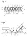
- a base 1 is shown onto which some of the internal parts are fitted, namely the foam edge 2.
- the base is made up of base part 3 which is intended to be fixedly attached to a mattress base with support 21, as will be explained in more detail with reference to Fig. 4 .
- Base 1 furthermore comprises the displaceable base parts 4 and 5, which are connected to the fixed base part 3.
- displaceable base part 6 which is displaceable with respect to the base part 5 which is also displaceable as such.
- the displaceable base parts 4 and 5 are each connected to the fixed base part 3 by means of the flange constructions 11, each of which consists of the flanges 12, 13 which are each connected to the mutually opposite edges 14 of the base parts 3, 4 and 3, 5, respectively, via a score line 9 or another pivot line.
- the flanges 12, 13 themselves are also attached to one another by means of a score line 10 or another pivot line.
- the base parts 5, 6 are also connected by such a flange construction 11.
- the base parts 3-6 and flanges 12, 13 thus form one single continuous unit which may, for example, be made from felt or another known material.
- the internal parts of the box are completed by a spring assembly 30 consisting of springs 7 whose axes are directed vertically.
- the springs 7 are connected to one another at the top in a known manner by means of spring elements 16 extending in the longitudinal direction and spring elements 18 extending in the transverse direction.
- the spring elements extending in the longitudinal direction are split into the spring element parts 17', 17", etc at the location of the flanges; spring elements 18 extending in the transverse direction are also provided there.
- the spring assembly is thus divided into spring assembly parts 30', 30", etc.
- the internal parts 29 comprising the foam edge 2 and the spring assembly 30 are finally covered by a cover 8 which is attached to the base 1 and indicated in Fig. 2 by means of dashed lines.
- the box 19 which is constructed in this manner is placed on a mattress base 20 as illustrated in Fig. 4 , which in turn rests on the support 21 placed on a floor.
- the mattress base is divided into a fixed mattress base part 22 and the displaceable mattress base parts 23-25.
- the displaceable mattress base part 23 is furthermore provided with a further displaceable mattress base part 23'.
- the mattress base parts 23, 24 are displaceable by means of actuators 26.
- the connection between the mattress base parts 23, 24 and 22 is designed as a hinge 27, the axis of which is at a distance above the support surface 28 defined by the mattress base 20.
- the mattress base parts 22, 23 and 24, 22 can move slightly apart during folding up, and conversely move towards one another during folding out. Due to the division of its base, the box 19 can readily follow such a mutual displacement. Even if the base parts 3, 4 and 5 of the box 19 have moved apart, the spring assembly parts 30', 30", etc. are still readily supported as a result of the flanges 12, 13.
Landscapes
- Health & Medical Sciences (AREA)
- General Health & Medical Sciences (AREA)
- Nursing (AREA)
- Mattresses And Other Support Structures For Chairs And Beds (AREA)
Applications Claiming Priority (1)
| Application Number | Priority Date | Filing Date | Title |
|---|---|---|---|
| NL2002426A NL2002426C2 (nl) | 2009-01-19 | 2009-01-19 | Verstelbare box voor een bed, alsmede combinatie van een dergelijke box en een ondermatras. |
Publications (1)
| Publication Number | Publication Date |
|---|---|
| EP2208444A1 true EP2208444A1 (fr) | 2010-07-21 |
Family
ID=40875109
Family Applications (1)
| Application Number | Title | Priority Date | Filing Date |
|---|---|---|---|
| EP10151041A Withdrawn EP2208444A1 (fr) | 2009-01-19 | 2010-01-19 | Sommier adaptable et la combinaison avec un support matelas |
Country Status (2)
| Country | Link |
|---|---|
| EP (1) | EP2208444A1 (fr) |
| NL (1) | NL2002426C2 (fr) |
Cited By (1)
| Publication number | Priority date | Publication date | Assignee | Title |
|---|---|---|---|---|
| EP4304420A4 (fr) * | 2021-03-09 | 2025-03-12 | Purple Innovation, LLC | Rails latéraux de matelas réglables |
Citations (4)
| Publication number | Priority date | Publication date | Assignee | Title |
|---|---|---|---|---|
| US4589151A (en) * | 1983-07-08 | 1986-05-20 | Behrens Robert S | Slatted bed system |
| DE9207808U1 (de) * | 1992-06-10 | 1992-10-22 | Kleindienst, Hans | Matratze |
| GB2347346A (en) * | 1999-03-03 | 2000-09-06 | Robert John Dudley Welch | Hinged mattress |
| EP1201164A1 (fr) * | 2000-10-28 | 2002-05-02 | Siddall and Hilton Limited | Dispositif pour supporter le corps humain |
-
2009
- 2009-01-19 NL NL2002426A patent/NL2002426C2/nl not_active IP Right Cessation
-
2010
- 2010-01-19 EP EP10151041A patent/EP2208444A1/fr not_active Withdrawn
Patent Citations (4)
| Publication number | Priority date | Publication date | Assignee | Title |
|---|---|---|---|---|
| US4589151A (en) * | 1983-07-08 | 1986-05-20 | Behrens Robert S | Slatted bed system |
| DE9207808U1 (de) * | 1992-06-10 | 1992-10-22 | Kleindienst, Hans | Matratze |
| GB2347346A (en) * | 1999-03-03 | 2000-09-06 | Robert John Dudley Welch | Hinged mattress |
| EP1201164A1 (fr) * | 2000-10-28 | 2002-05-02 | Siddall and Hilton Limited | Dispositif pour supporter le corps humain |
Cited By (1)
| Publication number | Priority date | Publication date | Assignee | Title |
|---|---|---|---|---|
| EP4304420A4 (fr) * | 2021-03-09 | 2025-03-12 | Purple Innovation, LLC | Rails latéraux de matelas réglables |
Also Published As
| Publication number | Publication date |
|---|---|
| NL2002426C2 (nl) | 2010-07-20 |
Similar Documents
| Publication | Publication Date | Title |
|---|---|---|
| US6295676B1 (en) | Mattress construction | |
| US6701551B1 (en) | Upholstered slat box spring/bed | |
| KR101962511B1 (ko) | 플렉시블 매트리스 지지대를 가진 접이식 침대 | |
| JP2002177097A (ja) | 身体支持配列部 | |
| RU2653474C2 (ru) | Предмет мебели с регулируемой степенью жесткости | |
| KR20190116733A (ko) | 매트리스 일체형 전동 침대 | |
| US6687929B2 (en) | Box spring corner guard | |
| CA3030739A1 (fr) | Fabrication de matelas a ressorts helicoidaux | |
| CN104029619A (zh) | 车辆座椅 | |
| CN109662505A (zh) | 可转换家具 | |
| JP6851584B2 (ja) | ベッドフレーム及びベッド | |
| EP1867255A1 (fr) | Housse double pour recouvrir des matelas une place côte à côte ou des structures internes de matelas disposées côte à côte de manière à fournir l'intérieur d'un matelas double, et matelas utilisant ladite housse | |
| US7216380B2 (en) | Corner guard for box spring | |
| US3941418A (en) | Upholstered seat | |
| US3098244A (en) | Support frame for furniture | |
| NL2002426C2 (nl) | Verstelbare box voor een bed, alsmede combinatie van een dergelijke box en een ondermatras. | |
| US8464373B2 (en) | Bed with slats | |
| US20220287469A1 (en) | Adjustable mattress side rails | |
| US7762629B2 (en) | Seating or reclining furniture | |
| EP2654513A1 (fr) | Support pour un matelas et lit comprenant un tel support | |
| JP6543035B2 (ja) | 折畳みベッド | |
| EP2116151B1 (fr) | Base de support de matelas à spirale réglable avec protection contre le pinçage | |
| US5231709A (en) | Support deck for mattress or seat | |
| JPH05237019A (ja) | クッション装置 | |
| EP4487735A1 (fr) | Système de support de lit et lit |
Legal Events
| Date | Code | Title | Description |
|---|---|---|---|
| PUAI | Public reference made under article 153(3) epc to a published international application that has entered the european phase |
Free format text: ORIGINAL CODE: 0009012 |
|
| AK | Designated contracting states |
Kind code of ref document: A1 Designated state(s): AT BE BG CH CY CZ DE DK EE ES FI FR GB GR HR HU IE IS IT LI LT LU LV MC MK MT NL NO PL PT RO SE SI SK SM TR |
|
| AX | Request for extension of the european patent |
Extension state: AL BA RS |
|
| STAA | Information on the status of an ep patent application or granted ep patent |
Free format text: STATUS: THE APPLICATION IS DEEMED TO BE WITHDRAWN |
|
| 18D | Application deemed to be withdrawn |
Effective date: 20110122 |