EP2208461B1 - Procédé de fabrication d'une bioélectrode - Google Patents
Procédé de fabrication d'une bioélectrode Download PDFInfo
- Publication number
- EP2208461B1 EP2208461B1 EP10000126.2A EP10000126A EP2208461B1 EP 2208461 B1 EP2208461 B1 EP 2208461B1 EP 10000126 A EP10000126 A EP 10000126A EP 2208461 B1 EP2208461 B1 EP 2208461B1
- Authority
- EP
- European Patent Office
- Prior art keywords
- electrical
- conducting element
- layer
- electrical conducting
- electrical conductor
- Prior art date
- Legal status (The legal status is an assumption and is not a legal conclusion. Google has not performed a legal analysis and makes no representation as to the accuracy of the status listed.)
- Active
Links
Images


Classifications
-
- A—HUMAN NECESSITIES
- A61—MEDICAL OR VETERINARY SCIENCE; HYGIENE
- A61B—DIAGNOSIS; SURGERY; IDENTIFICATION
- A61B5/00—Measuring for diagnostic purposes; Identification of persons
- A61B5/24—Detecting, measuring or recording bioelectric or biomagnetic signals of the body or parts thereof
- A61B5/25—Bioelectric electrodes therefor
- A61B5/251—Means for maintaining electrode contact with the body
- A61B5/257—Means for maintaining electrode contact with the body using adhesive means, e.g. adhesive pads or tapes
- A61B5/259—Means for maintaining electrode contact with the body using adhesive means, e.g. adhesive pads or tapes using conductive adhesive means, e.g. gels
-
- A—HUMAN NECESSITIES
- A61—MEDICAL OR VETERINARY SCIENCE; HYGIENE
- A61N—ELECTROTHERAPY; MAGNETOTHERAPY; RADIATION THERAPY; ULTRASOUND THERAPY
- A61N1/00—Electrotherapy; Circuits therefor
- A61N1/02—Details
- A61N1/04—Electrodes
- A61N1/0404—Electrodes for external use
- A61N1/0408—Use-related aspects
- A61N1/046—Specially adapted for shock therapy, e.g. defibrillation
-
- A—HUMAN NECESSITIES
- A61—MEDICAL OR VETERINARY SCIENCE; HYGIENE
- A61N—ELECTROTHERAPY; MAGNETOTHERAPY; RADIATION THERAPY; ULTRASOUND THERAPY
- A61N1/00—Electrotherapy; Circuits therefor
- A61N1/02—Details
- A61N1/04—Electrodes
- A61N1/0404—Electrodes for external use
- A61N1/0472—Structure-related aspects
- A61N1/048—Electrodes characterised by a specific connection between lead and electrode
-
- A—HUMAN NECESSITIES
- A61—MEDICAL OR VETERINARY SCIENCE; HYGIENE
- A61N—ELECTROTHERAPY; MAGNETOTHERAPY; RADIATION THERAPY; ULTRASOUND THERAPY
- A61N1/00—Electrotherapy; Circuits therefor
- A61N1/02—Details
- A61N1/04—Electrodes
- A61N1/0404—Electrodes for external use
- A61N1/0472—Structure-related aspects
- A61N1/0492—Patch electrodes
-
- A—HUMAN NECESSITIES
- A61—MEDICAL OR VETERINARY SCIENCE; HYGIENE
- A61B—DIAGNOSIS; SURGERY; IDENTIFICATION
- A61B2562/00—Details of sensors; Constructional details of sensor housings or probes; Accessories for sensors
- A61B2562/12—Manufacturing methods specially adapted for producing sensors for in-vivo measurements
- A61B2562/125—Manufacturing methods specially adapted for producing sensors for in-vivo measurements characterised by the manufacture of electrodes
-
- A—HUMAN NECESSITIES
- A61—MEDICAL OR VETERINARY SCIENCE; HYGIENE
- A61N—ELECTROTHERAPY; MAGNETOTHERAPY; RADIATION THERAPY; ULTRASOUND THERAPY
- A61N1/00—Electrotherapy; Circuits therefor
- A61N1/02—Details
- A61N1/04—Electrodes
- A61N1/0404—Electrodes for external use
- A61N1/0472—Structure-related aspects
- A61N1/0492—Patch electrodes
- A61N1/0496—Patch electrodes characterised by using specific chemical compositions, e.g. hydrogel compositions, adhesives
-
- Y—GENERAL TAGGING OF NEW TECHNOLOGICAL DEVELOPMENTS; GENERAL TAGGING OF CROSS-SECTIONAL TECHNOLOGIES SPANNING OVER SEVERAL SECTIONS OF THE IPC; TECHNICAL SUBJECTS COVERED BY FORMER USPC CROSS-REFERENCE ART COLLECTIONS [XRACs] AND DIGESTS
- Y10—TECHNICAL SUBJECTS COVERED BY FORMER USPC
- Y10T—TECHNICAL SUBJECTS COVERED BY FORMER US CLASSIFICATION
- Y10T29/00—Metal working
- Y10T29/49—Method of mechanical manufacture
- Y10T29/49002—Electrical device making
- Y10T29/49117—Conductor or circuit manufacturing
- Y10T29/49204—Contact or terminal manufacturing
Definitions
- the invention relates to a method for producing a bioelectrode according to the preamble of claim 1.
- Bioelectrodes are used in many ways. Either, as with the defibrillation electrode and the stimulation electrode, current is supplied to the human or animal body or current is removed from the body (for example neutral electrodes or measuring electrodes).
- Non-native bioelectrodes without fanned strands go out US 3,547,105 and the US 5,269,810 out.
- the object of the invention is to provide a method for producing a Bioelektrode, wherein the electrical connection cable has a good mechanical support in the electrode and also a good electrical contact is ensured to those layers of the electrode, which ultimately supply the flow of skin or to lose weight.
- the electrical guide element produced according to the invention can be mechanically fixed and electrically conductively connected to the electrical connection cable before the actual bioelectrode is assembled in a separate working process.
- the electrical guide element consists of a sheet-like layer of electrically conductive, thermoplastic material.
- the end of the connection cable may for example be surrounded by a curable material and thus form the preassembled electrical guide element.
- the preassembled electrical connection element also makes it possible to evenly distribute the current supplied via the electrical connection cable over a larger area or to remove it from a larger area. It is even possible in the electrically conductive Layer of the connection element, which may also consist of several sub-layers, to incorporate a special resistance profile, for example, such that the surface resistance decreases or increases from the middle connection point of the electrode-side cable end to the edge as needed. In any case, a targeted planar power distribution is possible. Further advantages and details of the invention will be explained in more detail with reference to the following description of the figures.
- Fig. 1a shows a first embodiment produced according to the invention in a schematic exploded view.
- Fig. 1b shows the electrode of the Fig. 1a in a schematic cross-sectional view.
- Fig. 1c shows a cable cross-section.
- Fig. 2a shows a second embodiment produced according to the invention in a schematic exploded view.
- Fig. 2b shows the electrode of the Fig. 2a in a schematic cross-sectional view.
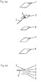
- Fig. 3a shows a third embodiment produced according to the invention in a schematic exploded view.
- Fig. 3b shows the electrode of the Fig. 3a in a schematic cross-sectional view.
- Fig. 4a shows a fourth embodiment produced according to the invention in a schematic exploded view.
- Fig. 4b shows the electrode of the Fig. 4a in a schematic cross-sectional view.
- Fig. 1a and 1b show a first embodiment of an electrode according to the invention, in particular defibrillation electrode.
- the electrode of the Fig. 1a and 1b has below a substrate 1 (eg: foam material consisting of polyethylene or the like, film consisting of polyethylene terephthalate or the like) on a thermoplastic layer 3, which is electrically conductive.
- the thermoplastic layer (3) may, for example: consist of polyvinyl chloride, Acrylbutadienstyrol, polyurethane, polyethylene or the like.
- the electrical conductivity of the thermoplastic layer 3 can be achieved, for example, by metallic inclusions and / or inclusions based on carbon (carbon black, graphite). By an appropriate distribution of these inclusions or a multi-layered layer 3, one can vary the electrical resistance across the electrode.
- an electrical guide element is preassembled on the electrode-side free end 4a of the connection cable 4.
- the electrical conducting element 2 consists of a hardened (preferably thermoplastic) electrically conductive mass which is mechanically fixed and electrically connected in good-conducting contact with the cable end 4a.
- the electrically conductive mass in which the cable end is arranged, preferably encapsulated, is layered according to the invention. This planar design allows a good installation in the bioelectrode, with a good mechanical support and a good electrical contact (in Fig. 1a to the electrically conductive layer 3) can be produced. In this case, the electrical guide element 2 has a low overall height.
- the electrical guide element 2 together with the cable end 4a has a layer thickness between 50 and 250 microns, preferably between 50 and 200 microns.
- This common layer thickness of the cable end 4a and guide element 2 applies in the entire bioelectrode, that is in the region between the skin-side adhesive layer 7 and a non-conductive substrate 1. If the layer thickness were less than 50 micrometers, this would lead to problems in welding. Too thick a guide element (over 250 microns), the flexibility of the electrode is no longer guaranteed, that is, the adaptability to the human body is lost or reduced.
- the electrical connection cable 4 comprises - as in Fig. 1c shown in cross section - an electrically insulating cable sheath 5, in which at least one electrical conductor 6 is located.
- This electrical conductor 6 is a strand, which consists of several individual wires / individual fibers.
- the guidewires may be carbon fiber strands consisting of several thousand to several tens of thousands of individual fibers which may be metallized. As leader even metal strands alone or metal strands combined with carbon fibers can be used.
- Such cable formation makes it possible to strip the cable end, for example, to a length of 0.5 cm to 5 cm, so that the conductor 6 is exposed.
- the preassembled electrical guide element 2 is then preferably not only connected to the stripped conductor area, but also to a part of the insulating cable sheath 5. This can be the mechanical support between the cable end 4 a and the electrical guide even further increase. According to the invention, it is provided to fan out the individual wires of the strand of the conductor and thus to achieve an improved hold and an improved electrical contact in the casting compound layer of the electrical conducting element 2.
- the electrical conductivity of the preferably thermoplastic layer of the electrical guide element 2 can be achieved, as in the case of the layer 3, by metallic inclusions and / or inclusions based on carbon (carbon black, graphite). By a corresponding distribution of these inclusions or a multi-layeredness of the electrical conducting element 2, one can also vary the electrical resistance over a certain surface area.
- the layer thickness of the electrical guide element is preferably of the order of 100 to 250 micrometers. This layer thickness applies both to the electrical guide element 2 alone and to the electrical guide element 2 together with the cable 4 or the electrical conductor 6 arranged therein or thereon Fig. 1b . 2 B and 3b the cable end 4a or the electrical conductor 6 is enclosed by the electrical guide element 2. However, it should not be ruled out that this electrical conductor 6 or the cable end 4a rests on or under the electrical guide element 2 at this, wherein the total layer thickness does not exceed 250 microns. This brings especially against the known from the prior art EP 0 337 667 B1 the advantage of far greater flexibility and the much lower maximum thickness of the bioelectrode.
- a conductive adhesive layer 7 preferably in the form of a conductive gel.
- the conductive adhesive layer which must be biocompatible, can be both an adhesive hydrogel and a conductive adhesive.
- a metal layer or a metal / metal chloride layer may be arranged, wherein the metal is preferably silver. This layer bears the reference numeral 8.
- a peelable cover material 9 is arranged below the conductive adhesive layer 7, which protects the conductive adhesive layer during transport and storage, and which is withdrawn before use.
- This cover material may consist of plastics such as polyethylene terephthalate, polystyrene, polypropylene or the like, which may also be siliconized.
- the second embodiment according to the Fig. 2a and 2b differs from the first embodiment according to the Fig. 1a and 1b essentially by a different design of the preassembled electrical conducting element 2 and by the fact that the electrically conductive thermoplastic intermediate layer 3 is missing, so that the preassembled electrical conducting element rests directly on the layer 8.
- the preassembled electrical conducting element has a relatively large area which is already more than 50%, preferably more than 70%, of the area of the skin-side electrically conductive adhesive layer 7.
- the electrical guide element 2 has been made a step upstream of the electrode construction in that the electrical conductor of the connecting cable 4 has been welded to a thermoplastic, electrically conductive layer.
- thermal welding processes or ultrasonic welding processes are examples of welding processes. In any case, it is ensured that the cable end has a good mechanical connection with the electrically conductive layer of the preassembled electrical conducting element 2.
- the electrical guide elements according to the invention can be produced optimized in terms of process in a separate working process in large numbers.
- these preassembled electrical guide elements together with cable end can then be easily used, which allows rapid production with high clock frequency.
- the preassembled electrical conducting element 2 rests directly on the upper side of the skin-side electrically conductive adhesive layer 7.
- the embodiment according to the Fig. 3a and 3b Is characterized by a small number of layers. The structure is particularly simple and therefore inexpensive. Nevertheless, a good mechanical hold of the cable end in the electrode is ensured by the preassembled electrical guide element 2. In addition, a good current distribution over the skin-side electrically conductive adhesive layer 7 can be achieved by a corresponding planar design of the preassembled electrical conducting element 2.
- the preassembled electrical conducting element is formed by the layer 3.
- the layer 3 There are two different manufacturing processes with respect to this embodiment.
- the fanned individual wires of the strand of the conductor are connected by means of an electrically conductive layer of carbon lacquer with the preassembled electrical guide element 3.
- the varnish dries and thereby keeps the individual wires of the strand intimately on the preassembled electrical conduction element 3.
- This varnish can consist of polyurethane or polyvinyl chloride binders or have these constituents.
- this filler may include, for example, carbon fibers, carbon black, graphite, metal pigments, etc.
- a binder-containing film for example made of carbon foil
- Esther or ketones can be used as solvents.
- the method according to the invention is characterized in a further variant in that initially a preferably layer-shaped electrical guide element 2 is attached to the electrode-side cable end 4a. Only then is this preassembled electrical guide element connected to at least one further layer of the bioelectrode, preferably by welding or gluing.
- the electrical guide element 2 is arranged substantially centrally in the bioelectrode, that is, that the electrical Guide element 2 on all sides from the edge of the bioelectrode or the outermost layers 1 and 7 or 1 and 9 is spaced apart.
- This distance should be as constant as possible. This distance is preferably between 3 and 20 mm, preferably between 5 and 15 mm.
- thermoplastic material of the preassembled electrical conducting element and / or the intermediate layer is electrically conductive by metallic inclusions and / or carbon-based inclusions.
- electrically conductive skin-side adhesive layer consists of a conductive hydrogel or electrically conductive adhesive.
- a metal layer or a metal / metal chloride layer to be arranged above the skin-side, electrically conductive adhesive layer, this metal being silver.
- a peelable cover material is arranged below the conductive adhesive layer and / or an electrically non-conductive carrier material, preferably of plastic, is arranged on the upper side of the electrode facing away from the skin.
- the bioelectrode is a defibrillation electrode, wherein the surface of that layer which is arranged on the side of the skin-side, electrically conductive adhesive layer facing away from the skin is preferably at least 50 cm 2 .
- the invention is of course not limited to the illustrated embodiments.
- the invention is useful not only for defibrillation electrodes and electrodes that deliver current to the skin (e.g., stimulation electrodes), but also for electrodes that remove current from the skin (eg, neutral electrodes, sensing electrodes).
- the layer structure and the size ratios may differ from the embodiments shown. It is essential that at the electrode end of the connecting cable, an electrical guide element is pre-assembled, over which a good mechanical support and a good electrical connection are ensured in the electrode.
Landscapes
- Health & Medical Sciences (AREA)
- Life Sciences & Earth Sciences (AREA)
- Engineering & Computer Science (AREA)
- Biomedical Technology (AREA)
- Animal Behavior & Ethology (AREA)
- General Health & Medical Sciences (AREA)
- Public Health (AREA)
- Veterinary Medicine (AREA)
- Nuclear Medicine, Radiotherapy & Molecular Imaging (AREA)
- Radiology & Medical Imaging (AREA)
- Chemical & Material Sciences (AREA)
- Dispersion Chemistry (AREA)
- Physics & Mathematics (AREA)
- Biophysics (AREA)
- Pathology (AREA)
- Heart & Thoracic Surgery (AREA)
- Medical Informatics (AREA)
- Molecular Biology (AREA)
- Surgery (AREA)
- Electrotherapy Devices (AREA)
- Measurement And Recording Of Electrical Phenomena And Electrical Characteristics Of The Living Body (AREA)
Claims (2)
- Procédé de fabrication d'une bioélectrode, avec une couche adhésive (7) électriquement conductrice, côté peau et avec un câble de raccordement électrique flexible (4) qui comprend, dans une gaine de câble isolée électriquement (5), au moins un conducteur électrique (6) sous forme de toron composé de plusieurs brins ou monofilaments conducteurs, caractérisé par les étapes de :- répartition des brins ou monofilaments du toron,- prémontage d'un élément conducteur électrique (2, 3) à l'extrémité côté électrode (4a) du câble de raccordement (4), moyennant quoi l'élément conducteur (2, 3) est raccordé aux brins ou monofilaments répartis du toron du conducteur électrique (6) du câble de raccordement (4), dans lequel l'élément conducteur électrique (2, 3) et le conducteur électrique (6) qui y est agencé dedans sont réalisés dans la bioélectrode sous forme de couche avec une épaisseur de couche commune entre 50 et 250 micromètres, et- ensuite raccordement électrique de l'élément conducteur électrique (2, 3) prémonté, le cas échéant par interconnexion d'au moins une autre couche électriquement conductrice (3, 8), à la couche adhésive (7) électriquement conductrice, côté peau,dans lequel il est réalisé en outre :- que l'élément conducteur électrique (2, 3) prémonté est formé d'une couche électriquement conductrice, que la couche de l'élément conducteur électrique (2) prémonté se compose d'un matériau thermoplastique électriquement conducteur et que le conducteur électrique (6) du câble de raccordement (4) est soudé avec la couche thermoplastique électriquement conductrice, dans lequel la couche soudée forme l'élément conducteur électrique (2) prémonté,ou- équipement de l'élément conducteur électrique (3) ou du conducteur électrique (6) du câble de raccordement (4) d'une couche de vernis électriquement conductrice et pose du conducteur électrique (6) du câble de raccordement (4) sur l'élément conducteur électrique (3) de sorte que le conducteur électrique (6) soit raccordé par le séchage de la couche de vernis à l'élément conducteur électrique (3),dans lequel le vernis de la couche de vernis se compose de liant de polyuréthane ou liant de polychlorure de vinyle ou présente ces composants,
ou- utilisation d'une feuille contenant un liant, soluble par solvant en tant qu'élément conducteur électrique (3), dissolution de cette feuille par un solvant adapté et pose du conducteur électrique (6) du câble de raccordement (4) sur les zones dissoutes de sorte que le conducteur électrique (6) soit raccordé par le séchage du liant de la feuille à l'élément conducteur électrique (3). - Procédé selon la revendication 1, caractérisé en ce qu'une feuille de carbone contenant un liant, soluble par solvant est utilisée en tant qu'élément conducteur électrique (3).
Applications Claiming Priority (2)
| Application Number | Priority Date | Filing Date | Title |
|---|---|---|---|
| AT852009 | 2009-01-20 | ||
| AT0117309A AT507855A1 (de) | 2009-01-20 | 2009-07-27 | Bioelektrode |
Publications (2)
| Publication Number | Publication Date |
|---|---|
| EP2208461A1 EP2208461A1 (fr) | 2010-07-21 |
| EP2208461B1 true EP2208461B1 (fr) | 2018-12-12 |
Family
ID=41650221
Family Applications (1)
| Application Number | Title | Priority Date | Filing Date |
|---|---|---|---|
| EP10000126.2A Active EP2208461B1 (fr) | 2009-01-20 | 2010-01-08 | Procédé de fabrication d'une bioélectrode |
Country Status (4)
| Country | Link |
|---|---|
| US (1) | US8989874B2 (fr) |
| EP (1) | EP2208461B1 (fr) |
| AT (2) | AT507855A1 (fr) |
| ES (1) | ES2715635T3 (fr) |
Families Citing this family (6)
| Publication number | Priority date | Publication date | Assignee | Title |
|---|---|---|---|---|
| DE102015113921A1 (de) * | 2015-08-21 | 2017-02-23 | K.L. Kaschier- Und Laminier Gmbh | Materialbahn und Heizelement |
| DE102018205552A1 (de) * | 2018-04-12 | 2019-10-17 | Zf Friedrichshafen Ag | Verfahren zum Herstellen einer Sensoreinrichtung, Verfahren zum Anordnen einer Sensoreinrichtung sowie Fahrwerkbauteil mit einer Sensoreinrichtung |
| AT522511B1 (de) * | 2019-04-16 | 2023-08-15 | Leonh Lang Holding Gmbh | Elektrode zum Anbringen auf der menschlichen Haut und Verfahren zum Herstellen einer Elektrode |
| KR20240051241A (ko) * | 2021-08-31 | 2024-04-19 | 노보큐어 게엠베하 | 전도성 접착제 복합체를 포함하는 피부 접촉층을 가지는 전극 어셈블리 및 이를 이용한 종양 치료 필드를 적용하는 시스템 및 방법 |
| US12599765B2 (en) | 2021-12-14 | 2026-04-14 | Novocure Gmbh | Shifting of transducer array to reduce skin irritation |
| US12268863B2 (en) | 2023-02-06 | 2025-04-08 | Novocure Gmbh | Shiftable transducer array with anisotropic material layer |
Citations (1)
| Publication number | Priority date | Publication date | Assignee | Title |
|---|---|---|---|---|
| WO2008017921A2 (fr) * | 2006-08-07 | 2008-02-14 | Politecnico Di Torino | Système et procédé d'acquisition de signaux bioélectriques par le biais d'électrodes de surface |
Family Cites Families (18)
| Publication number | Priority date | Publication date | Assignee | Title |
|---|---|---|---|---|
| US3547105A (en) * | 1968-08-29 | 1970-12-15 | T O Paine | Flexible conductive disc electrode |
| US4092985A (en) * | 1974-11-25 | 1978-06-06 | John George Kaufman | Body electrode for electro-medical use |
| US4008721A (en) | 1975-04-14 | 1977-02-22 | Medtronic, Inc. | Tape electrode for transmitting electrical signals through the skin |
| CA1203286A (fr) | 1982-06-16 | 1986-04-15 | Minnesota Mining And Manufacturing Company | Bioelectrode |
| US4899754A (en) | 1986-10-03 | 1990-02-13 | Minnesota Mining And Manufacturing Company | Flat, conformable, biomedical electrode allowing removal of electrical lead wire |
| US4736752A (en) * | 1986-11-28 | 1988-04-12 | Axelgaard Manufacturing Co., Ltd. | Transcutaneous medical electrode |
| NL8702534A (nl) | 1987-10-23 | 1989-05-16 | Arne Sippens Groenewegen | Elektrodesamenstel alsmede werkwijze voor het vervaardigen daarvan. |
| US5269810A (en) * | 1992-06-19 | 1993-12-14 | W. L. Gore & Associates, Inc. | Patch electrode |
| US5857858A (en) * | 1996-12-23 | 1999-01-12 | General Electric Company | Demountable and repairable low pitch interconnect for stacked multichip modules |
| EP0970719A3 (fr) * | 1998-07-08 | 2000-08-23 | Nitto Denko Corporation | Structure d'électrode |
| CA2393970C (fr) * | 1999-12-10 | 2004-07-20 | Thermion Systems International | Dispositif de chauffage de stratifie thermoplastique et procede de fabrication associe |
| JP2002005868A (ja) * | 2000-06-16 | 2002-01-09 | Yamatake Corp | 検出器 |
| AU2002230684A1 (en) | 2000-11-16 | 2002-05-27 | Axelgaard Manufacturing Company, Ltd. | Dual element sensor medical electrode |
| US7187985B2 (en) * | 2003-07-18 | 2007-03-06 | 3M Innovative Properties Company | Biomedical electrode with current spreading layer |
| US7169644B2 (en) * | 2004-08-19 | 2007-01-30 | Ferrari R Keith | Method of making multifunction electrode |
| US20060095001A1 (en) * | 2004-10-29 | 2006-05-04 | Transcutaneous Technologies Inc. | Electrode and iontophoresis device |
| US7697997B2 (en) | 2006-01-10 | 2010-04-13 | Conmed Corporation | Multifunction electrode pad |
| US7742828B2 (en) * | 2006-09-29 | 2010-06-22 | Tyco Healthcare Group Lp | Medical electrode suitable for high-energy stimulation |
-
2009
- 2009-07-27 AT AT0117309A patent/AT507855A1/de active IP Right Grant
-
2010
- 2010-01-08 EP EP10000126.2A patent/EP2208461B1/fr active Active
- 2010-01-08 ES ES10000126T patent/ES2715635T3/es active Active
- 2010-01-08 US US12/684,494 patent/US8989874B2/en active Active
- 2010-08-18 AT AT0806610U patent/AT12123U1/de not_active IP Right Cessation
Patent Citations (1)
| Publication number | Priority date | Publication date | Assignee | Title |
|---|---|---|---|---|
| WO2008017921A2 (fr) * | 2006-08-07 | 2008-02-14 | Politecnico Di Torino | Système et procédé d'acquisition de signaux bioélectriques par le biais d'électrodes de surface |
Also Published As
| Publication number | Publication date |
|---|---|
| ES2715635T3 (es) | 2019-06-05 |
| AT12123U1 (de) | 2011-11-15 |
| AT507855A1 (de) | 2010-08-15 |
| US20100185078A1 (en) | 2010-07-22 |
| EP2208461A1 (fr) | 2010-07-21 |
| US8989874B2 (en) | 2015-03-24 |
Similar Documents
| Publication | Publication Date | Title |
|---|---|---|
| DE60131997T2 (de) | Schwimmende elektrode | |
| EP2208461B1 (fr) | Procédé de fabrication d'une bioélectrode | |
| DE69326080T2 (de) | Implantierbare elektrode | |
| DE2726742C2 (de) | Zwischenverbindungsstück | |
| EP3292885B1 (fr) | Système de conducteur d'électrode élastique et implant médical | |
| DE2538898A1 (de) | Elektrode fuer elektrokardiographische messungen | |
| EP2196237B1 (fr) | Bioélectrode | |
| DE10046489C1 (de) | Lötbares elektrisches Anschlußelement mit Lotdepot und dessen Verwendung | |
| EP1162631B1 (fr) | Connecteur pour connecter un câble-ruban plat | |
| EP3207956B1 (fr) | Procédé de fabrication d'une conduite d'électrodes ou d'un cathéter | |
| AT519280A1 (de) | Elektrode zum Anbringen auf der menschlichen Haut | |
| DE8008351U1 (de) | Mehradriger Verbinder | |
| DE102011007138B4 (de) | Elektrodenanordnung, Herstellungsverfahren | |
| DE3530269C2 (de) | Implantierbare indifferente Elektrode zur Herzstimulation | |
| DE2707620A1 (de) | Elektronische experimentiereinrichtung | |
| EP2000005B1 (fr) | Système de mise en contact, élément de chauffage et production d'un système de mise en contact et d'un élément de chauffage | |
| WO2006007829A1 (fr) | Ligne de raccordement electrique pour elements implantes et procede de fabrication associe | |
| EP3181187B1 (fr) | Électrode implantable comprenant une enveloppe cylindrique creuse | |
| DE20204011U1 (de) | Elektrische Verbindungsanordnung mit einer Folienleiterplatte oder einem Folienleiterkabel sowie elektrisches Brückenelement und Verarbeitungseinheit für diese Anordnung | |
| AT522148A4 (de) | Elektrode | |
| DE19932996C2 (de) | Leiter mit Flexiblem Teil | |
| EP1122823B1 (fr) | Contact à sertir | |
| DE102009059304A1 (de) | Elektronische/optische Komponenten mit einem daran befestigten Kabel und Verfahen zur Befestigung des Kabels | |
| DE102024108531A1 (de) | Leitung für eine medizinische Vorrichtung | |
| WO2024168370A1 (fr) | Électrode destinée à être fixée à la peau humaine |
Legal Events
| Date | Code | Title | Description |
|---|---|---|---|
| PUAI | Public reference made under article 153(3) epc to a published international application that has entered the european phase |
Free format text: ORIGINAL CODE: 0009012 |
|
| AK | Designated contracting states |
Kind code of ref document: A1 Designated state(s): AT BE BG CH CY CZ DE DK EE ES FI FR GB GR HR HU IE IS IT LI LT LU LV MC MK MT NL NO PL PT RO SE SI SK SM TR |
|
| AX | Request for extension of the european patent |
Extension state: AL BA RS |
|
| 17P | Request for examination filed |
Effective date: 20101229 |
|
| 17Q | First examination report despatched |
Effective date: 20140429 |
|
| GRAP | Despatch of communication of intention to grant a patent |
Free format text: ORIGINAL CODE: EPIDOSNIGR1 |
|
| STAA | Information on the status of an ep patent application or granted ep patent |
Free format text: STATUS: GRANT OF PATENT IS INTENDED |
|
| INTG | Intention to grant announced |
Effective date: 20180831 |
|
| GRAS | Grant fee paid |
Free format text: ORIGINAL CODE: EPIDOSNIGR3 |
|
| GRAA | (expected) grant |
Free format text: ORIGINAL CODE: 0009210 |
|
| STAA | Information on the status of an ep patent application or granted ep patent |
Free format text: STATUS: THE PATENT HAS BEEN GRANTED |
|
| AK | Designated contracting states |
Kind code of ref document: B1 Designated state(s): AT BE BG CH CY CZ DE DK EE ES FI FR GB GR HR HU IE IS IT LI LT LU LV MC MK MT NL NO PL PT RO SE SI SK SM TR |
|
| REG | Reference to a national code |
Ref country code: GB Ref legal event code: FG4D Free format text: NOT ENGLISH |
|
| REG | Reference to a national code |
Ref country code: CH Ref legal event code: EP |
|
| REG | Reference to a national code |
Ref country code: AT Ref legal event code: REF Ref document number: 1074934 Country of ref document: AT Kind code of ref document: T Effective date: 20181215 |
|
| REG | Reference to a national code |
Ref country code: DE Ref legal event code: R096 Ref document number: 502010015614 Country of ref document: DE |
|
| REG | Reference to a national code |
Ref country code: IE Ref legal event code: FG4D Free format text: LANGUAGE OF EP DOCUMENT: GERMAN |
|
| REG | Reference to a national code |
Ref country code: NL Ref legal event code: MP Effective date: 20181212 |
|
| REG | Reference to a national code |
Ref country code: LT Ref legal event code: MG4D |
|
| PG25 | Lapsed in a contracting state [announced via postgrant information from national office to epo] |
Ref country code: LT Free format text: LAPSE BECAUSE OF FAILURE TO SUBMIT A TRANSLATION OF THE DESCRIPTION OR TO PAY THE FEE WITHIN THE PRESCRIBED TIME-LIMIT Effective date: 20181212 Ref country code: BG Free format text: LAPSE BECAUSE OF FAILURE TO SUBMIT A TRANSLATION OF THE DESCRIPTION OR TO PAY THE FEE WITHIN THE PRESCRIBED TIME-LIMIT Effective date: 20190312 Ref country code: NO Free format text: LAPSE BECAUSE OF FAILURE TO SUBMIT A TRANSLATION OF THE DESCRIPTION OR TO PAY THE FEE WITHIN THE PRESCRIBED TIME-LIMIT Effective date: 20190312 Ref country code: HR Free format text: LAPSE BECAUSE OF FAILURE TO SUBMIT A TRANSLATION OF THE DESCRIPTION OR TO PAY THE FEE WITHIN THE PRESCRIBED TIME-LIMIT Effective date: 20181212 Ref country code: LV Free format text: LAPSE BECAUSE OF FAILURE TO SUBMIT A TRANSLATION OF THE DESCRIPTION OR TO PAY THE FEE WITHIN THE PRESCRIBED TIME-LIMIT Effective date: 20181212 Ref country code: FI Free format text: LAPSE BECAUSE OF FAILURE TO SUBMIT A TRANSLATION OF THE DESCRIPTION OR TO PAY THE FEE WITHIN THE PRESCRIBED TIME-LIMIT Effective date: 20181212 |
|
| PG25 | Lapsed in a contracting state [announced via postgrant information from national office to epo] |
Ref country code: GR Free format text: LAPSE BECAUSE OF FAILURE TO SUBMIT A TRANSLATION OF THE DESCRIPTION OR TO PAY THE FEE WITHIN THE PRESCRIBED TIME-LIMIT Effective date: 20190313 Ref country code: SE Free format text: LAPSE BECAUSE OF FAILURE TO SUBMIT A TRANSLATION OF THE DESCRIPTION OR TO PAY THE FEE WITHIN THE PRESCRIBED TIME-LIMIT Effective date: 20181212 |
|
| REG | Reference to a national code |
Ref country code: ES Ref legal event code: FG2A Ref document number: 2715635 Country of ref document: ES Kind code of ref document: T3 Effective date: 20190605 |
|
| PG25 | Lapsed in a contracting state [announced via postgrant information from national office to epo] |
Ref country code: NL Free format text: LAPSE BECAUSE OF FAILURE TO SUBMIT A TRANSLATION OF THE DESCRIPTION OR TO PAY THE FEE WITHIN THE PRESCRIBED TIME-LIMIT Effective date: 20181212 |
|
| PG25 | Lapsed in a contracting state [announced via postgrant information from national office to epo] |
Ref country code: PL Free format text: LAPSE BECAUSE OF FAILURE TO SUBMIT A TRANSLATION OF THE DESCRIPTION OR TO PAY THE FEE WITHIN THE PRESCRIBED TIME-LIMIT Effective date: 20181212 Ref country code: CZ Free format text: LAPSE BECAUSE OF FAILURE TO SUBMIT A TRANSLATION OF THE DESCRIPTION OR TO PAY THE FEE WITHIN THE PRESCRIBED TIME-LIMIT Effective date: 20181212 Ref country code: PT Free format text: LAPSE BECAUSE OF FAILURE TO SUBMIT A TRANSLATION OF THE DESCRIPTION OR TO PAY THE FEE WITHIN THE PRESCRIBED TIME-LIMIT Effective date: 20190412 |
|
| PG25 | Lapsed in a contracting state [announced via postgrant information from national office to epo] |
Ref country code: SM Free format text: LAPSE BECAUSE OF FAILURE TO SUBMIT A TRANSLATION OF THE DESCRIPTION OR TO PAY THE FEE WITHIN THE PRESCRIBED TIME-LIMIT Effective date: 20181212 Ref country code: IS Free format text: LAPSE BECAUSE OF FAILURE TO SUBMIT A TRANSLATION OF THE DESCRIPTION OR TO PAY THE FEE WITHIN THE PRESCRIBED TIME-LIMIT Effective date: 20190412 Ref country code: SK Free format text: LAPSE BECAUSE OF FAILURE TO SUBMIT A TRANSLATION OF THE DESCRIPTION OR TO PAY THE FEE WITHIN THE PRESCRIBED TIME-LIMIT Effective date: 20181212 Ref country code: EE Free format text: LAPSE BECAUSE OF FAILURE TO SUBMIT A TRANSLATION OF THE DESCRIPTION OR TO PAY THE FEE WITHIN THE PRESCRIBED TIME-LIMIT Effective date: 20181212 Ref country code: RO Free format text: LAPSE BECAUSE OF FAILURE TO SUBMIT A TRANSLATION OF THE DESCRIPTION OR TO PAY THE FEE WITHIN THE PRESCRIBED TIME-LIMIT Effective date: 20181212 |
|
| REG | Reference to a national code |
Ref country code: CH Ref legal event code: PL |
|
| REG | Reference to a national code |
Ref country code: DE Ref legal event code: R097 Ref document number: 502010015614 Country of ref document: DE |
|
| PG25 | Lapsed in a contracting state [announced via postgrant information from national office to epo] |
Ref country code: LU Free format text: LAPSE BECAUSE OF NON-PAYMENT OF DUE FEES Effective date: 20190108 |
|
| REG | Reference to a national code |
Ref country code: BE Ref legal event code: MM Effective date: 20190131 |
|
| PLBE | No opposition filed within time limit |
Free format text: ORIGINAL CODE: 0009261 |
|
| STAA | Information on the status of an ep patent application or granted ep patent |
Free format text: STATUS: NO OPPOSITION FILED WITHIN TIME LIMIT |
|
| REG | Reference to a national code |
Ref country code: IE Ref legal event code: MM4A |
|
| PG25 | Lapsed in a contracting state [announced via postgrant information from national office to epo] |
Ref country code: MC Free format text: LAPSE BECAUSE OF FAILURE TO SUBMIT A TRANSLATION OF THE DESCRIPTION OR TO PAY THE FEE WITHIN THE PRESCRIBED TIME-LIMIT Effective date: 20181212 Ref country code: SI Free format text: LAPSE BECAUSE OF FAILURE TO SUBMIT A TRANSLATION OF THE DESCRIPTION OR TO PAY THE FEE WITHIN THE PRESCRIBED TIME-LIMIT Effective date: 20181212 Ref country code: DK Free format text: LAPSE BECAUSE OF FAILURE TO SUBMIT A TRANSLATION OF THE DESCRIPTION OR TO PAY THE FEE WITHIN THE PRESCRIBED TIME-LIMIT Effective date: 20181212 |
|
| 26N | No opposition filed |
Effective date: 20190913 |
|
| PG25 | Lapsed in a contracting state [announced via postgrant information from national office to epo] |
Ref country code: BE Free format text: LAPSE BECAUSE OF NON-PAYMENT OF DUE FEES Effective date: 20190131 |
|
| PG25 | Lapsed in a contracting state [announced via postgrant information from national office to epo] |
Ref country code: CH Free format text: LAPSE BECAUSE OF NON-PAYMENT OF DUE FEES Effective date: 20190131 Ref country code: LI Free format text: LAPSE BECAUSE OF NON-PAYMENT OF DUE FEES Effective date: 20190131 |
|
| PG25 | Lapsed in a contracting state [announced via postgrant information from national office to epo] |
Ref country code: IE Free format text: LAPSE BECAUSE OF NON-PAYMENT OF DUE FEES Effective date: 20190108 |
|
| REG | Reference to a national code |
Ref country code: AT Ref legal event code: MM01 Ref document number: 1074934 Country of ref document: AT Kind code of ref document: T Effective date: 20190108 |
|
| PG25 | Lapsed in a contracting state [announced via postgrant information from national office to epo] |
Ref country code: TR Free format text: LAPSE BECAUSE OF FAILURE TO SUBMIT A TRANSLATION OF THE DESCRIPTION OR TO PAY THE FEE WITHIN THE PRESCRIBED TIME-LIMIT Effective date: 20181212 |
|
| PG25 | Lapsed in a contracting state [announced via postgrant information from national office to epo] |
Ref country code: AT Free format text: LAPSE BECAUSE OF NON-PAYMENT OF DUE FEES Effective date: 20190108 |
|
| PG25 | Lapsed in a contracting state [announced via postgrant information from national office to epo] |
Ref country code: MT Free format text: LAPSE BECAUSE OF FAILURE TO SUBMIT A TRANSLATION OF THE DESCRIPTION OR TO PAY THE FEE WITHIN THE PRESCRIBED TIME-LIMIT Effective date: 20181212 |
|
| REG | Reference to a national code |
Ref country code: DE Ref legal event code: R079 Ref document number: 502010015614 Country of ref document: DE Free format text: PREVIOUS MAIN CLASS: A61B0005040800 Ipc: A61B0005280000 |
|
| PG25 | Lapsed in a contracting state [announced via postgrant information from national office to epo] |
Ref country code: CY Free format text: LAPSE BECAUSE OF FAILURE TO SUBMIT A TRANSLATION OF THE DESCRIPTION OR TO PAY THE FEE WITHIN THE PRESCRIBED TIME-LIMIT Effective date: 20181212 |
|
| PG25 | Lapsed in a contracting state [announced via postgrant information from national office to epo] |
Ref country code: HU Free format text: LAPSE BECAUSE OF FAILURE TO SUBMIT A TRANSLATION OF THE DESCRIPTION OR TO PAY THE FEE WITHIN THE PRESCRIBED TIME-LIMIT; INVALID AB INITIO Effective date: 20100108 |
|
| PG25 | Lapsed in a contracting state [announced via postgrant information from national office to epo] |
Ref country code: MK Free format text: LAPSE BECAUSE OF FAILURE TO SUBMIT A TRANSLATION OF THE DESCRIPTION OR TO PAY THE FEE WITHIN THE PRESCRIBED TIME-LIMIT Effective date: 20181212 |
|
| P01 | Opt-out of the competence of the unified patent court (upc) registered |
Effective date: 20230522 |
|
| PGFP | Annual fee paid to national office [announced via postgrant information from national office to epo] |
Ref country code: GB Payment date: 20260126 Year of fee payment: 17 |
|
| PGFP | Annual fee paid to national office [announced via postgrant information from national office to epo] |
Ref country code: ES Payment date: 20260210 Year of fee payment: 17 |
|
| PGFP | Annual fee paid to national office [announced via postgrant information from national office to epo] |
Ref country code: DE Payment date: 20260127 Year of fee payment: 17 |
|
| PGFP | Annual fee paid to national office [announced via postgrant information from national office to epo] |
Ref country code: IT Payment date: 20260123 Year of fee payment: 17 |
|
| PGFP | Annual fee paid to national office [announced via postgrant information from national office to epo] |
Ref country code: FR Payment date: 20260126 Year of fee payment: 17 |