EP2196237B1 - Bioélectrode - Google Patents
Bioélectrode Download PDFInfo
- Publication number
- EP2196237B1 EP2196237B1 EP20090015126 EP09015126A EP2196237B1 EP 2196237 B1 EP2196237 B1 EP 2196237B1 EP 20090015126 EP20090015126 EP 20090015126 EP 09015126 A EP09015126 A EP 09015126A EP 2196237 B1 EP2196237 B1 EP 2196237B1
- Authority
- EP
- European Patent Office
- Prior art keywords
- layer
- thermoplastic layers
- bioelectrode according
- skin
- connecting cable
- Prior art date
- Legal status (The legal status is an assumption and is not a legal conclusion. Google has not performed a legal analysis and makes no representation as to the accuracy of the status listed.)
- Active
Links
Images


Classifications
-
- A—HUMAN NECESSITIES
- A61—MEDICAL OR VETERINARY SCIENCE; HYGIENE
- A61N—ELECTROTHERAPY; MAGNETOTHERAPY; RADIATION THERAPY; ULTRASOUND THERAPY
- A61N1/00—Electrotherapy; Circuits therefor
- A61N1/02—Details
- A61N1/04—Electrodes
- A61N1/0404—Electrodes for external use
- A61N1/0408—Use-related aspects
- A61N1/046—Specially adapted for shock therapy, e.g. defibrillation
-
- A—HUMAN NECESSITIES
- A61—MEDICAL OR VETERINARY SCIENCE; HYGIENE
- A61B—DIAGNOSIS; SURGERY; IDENTIFICATION
- A61B5/00—Measuring for diagnostic purposes; Identification of persons
- A61B5/24—Detecting, measuring or recording bioelectric or biomagnetic signals of the body or parts thereof
- A61B5/25—Bioelectric electrodes therefor
- A61B5/251—Means for maintaining electrode contact with the body
- A61B5/257—Means for maintaining electrode contact with the body using adhesive means, e.g. adhesive pads or tapes
- A61B5/259—Means for maintaining electrode contact with the body using adhesive means, e.g. adhesive pads or tapes using conductive adhesive means, e.g. gels
-
- A—HUMAN NECESSITIES
- A61—MEDICAL OR VETERINARY SCIENCE; HYGIENE
- A61N—ELECTROTHERAPY; MAGNETOTHERAPY; RADIATION THERAPY; ULTRASOUND THERAPY
- A61N1/00—Electrotherapy; Circuits therefor
- A61N1/02—Details
- A61N1/04—Electrodes
- A61N1/0404—Electrodes for external use
- A61N1/0472—Structure-related aspects
- A61N1/048—Electrodes characterised by a specific connection between lead and electrode
-
- A—HUMAN NECESSITIES
- A61—MEDICAL OR VETERINARY SCIENCE; HYGIENE
- A61N—ELECTROTHERAPY; MAGNETOTHERAPY; RADIATION THERAPY; ULTRASOUND THERAPY
- A61N1/00—Electrotherapy; Circuits therefor
- A61N1/02—Details
- A61N1/04—Electrodes
- A61N1/0404—Electrodes for external use
- A61N1/0472—Structure-related aspects
- A61N1/0492—Patch electrodes
-
- A—HUMAN NECESSITIES
- A61—MEDICAL OR VETERINARY SCIENCE; HYGIENE
- A61B—DIAGNOSIS; SURGERY; IDENTIFICATION
- A61B18/00—Surgical instruments, devices or methods for transferring non-mechanical forms of energy to or from the body
- A61B18/04—Surgical instruments, devices or methods for transferring non-mechanical forms of energy to or from the body by heating
- A61B18/12—Surgical instruments, devices or methods for transferring non-mechanical forms of energy to or from the body by heating by passing a current through the tissue to be heated, e.g. high-frequency current
- A61B18/14—Probes or electrodes therefor
- A61B18/16—Indifferent or passive electrodes for grounding
-
- A—HUMAN NECESSITIES
- A61—MEDICAL OR VETERINARY SCIENCE; HYGIENE
- A61N—ELECTROTHERAPY; MAGNETOTHERAPY; RADIATION THERAPY; ULTRASOUND THERAPY
- A61N1/00—Electrotherapy; Circuits therefor
- A61N1/02—Details
- A61N1/04—Electrodes
- A61N1/0404—Electrodes for external use
- A61N1/0472—Structure-related aspects
- A61N1/0492—Patch electrodes
- A61N1/0496—Patch electrodes characterised by using specific chemical compositions, e.g. hydrogel compositions, adhesives
-
- A—HUMAN NECESSITIES
- A61—MEDICAL OR VETERINARY SCIENCE; HYGIENE
- A61N—ELECTROTHERAPY; MAGNETOTHERAPY; RADIATION THERAPY; ULTRASOUND THERAPY
- A61N1/00—Electrotherapy; Circuits therefor
- A61N1/18—Applying electric currents by contact electrodes
- A61N1/32—Applying electric currents by contact electrodes alternating or intermittent currents
Definitions
- the invention relates to a bioelectrode having a skin-side, electrically conductive adhesive layer, a flexible electrical connection cable which comprises at least one electrical conductor, preferably in the form of a strand consisting of a plurality of individual wires or conductive individual fibers, in an electrically insulating cable sheath, and two thermoplastic layers which are electrically conductive and are electrically connected to the electrical conductor of the connection cable, wherein the electrode-side end of the connection cable between the two thermoplastic layers is arranged.
- Bioelectrodes are used in many ways. As with defibrillation electrodes and stimulation electrodes, current is either supplied to the human or animal body or current is removed from the body (for example neutral electrodes or measuring electrodes).
- connection cable between two electrically conductive adhesive tapes, these two adhesive tapes are glued together only in a simple manner and thus give a relatively poor mechanical grip and poor electrical connection to the ends of the connection cable.
- XP-002572097 of the 3M Technical Bulletin discloses typical properties for electrically conductive adhesive films, wherein, for example, under No. 9713 an electrically conductive adhesive film is shown which can be bonded together at room temperature and low pressure.
- the disadvantage here is that this compound is solvable and that only the adhesive film of the adhesive tape is electrically conductive.
- the object of the invention is to provide a bioelectrode in which the electrical connection cable has a good mechanical hold in the electrode and, in addition, good electrical contact with those layers of the electrode is ensured, which ultimately supply or remove the current from the skin.
- thermoplastic layers are at least partially welded together
- the two thermoplastic layers including the electrode-side connecting cable are thermally or ultrasonically welded together.
- connection according to the invention of the electrode-side connection end between two thermally or ultrasonically welded thermoplastic layers makes it possible, on the one hand, to achieve a good mechanical hold, and at the same time to produce an excellent electrical connection with the two thermoplastic layers, which are designed to be electrically conductive.
- the electrically conductive, thermoplastic layers allow the current supplied via the electrical connecting cable to be distributed uniformly over a larger area or to be removed from a larger area. But it is also possible to incorporate in the electrically conductive thermoplastic layer, which may also consist of several sub-layers, a special resistance profile, for example, such that the surface resistance decreases from the middle point of the electrode-side cable end to the edge of the electrically conductive thermoplastic layer as needed, or increases. In any case, a targeted planar power distribution is possible.
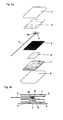
- Fig. 1a shows a first embodiment of the invention in a schematic exploded view.
- Fig. 1b shows the electrode of the Fig. 1a in a schematic cross-sectional view.
- Fig. 1 c shows a cable cross-section.
- Fig. 2a shows a second embodiment of the invention in a schematic exploded view.
- Fig. 2b shows the electrode of the Fig. 2a in a schematic cross-sectional view.
- Fig. 3a shows a third embodiment of the invention in a schematic exploded view.
- Fig. 3b shows the electrode of the Fig. 3a in a schematic cross-sectional view.
- Fig. 4a shows a fourth embodiment of the invention in a schematic exploded view.
- Fig. 4b shows the electrode of the Fig. 4a in a schematic cross-sectional view.
- Fig. 5a shows a fifth embodiment of the invention in a schematic exploded view.
- Fig. 5b shows the electrode of the Fig. 5a in a schematic cross-sectional view.
- Fig. 6a shows a sixth embodiment of the invention in a schematic exploded view.
- Fig. 6b shows the electrode of the Fig. 6a in a schematic cross-sectional view.
- Fig. 1a and 1b show a first embodiment of an electrode according to the invention, in particular defibrillation electrode.
- the electrode of the Fig. 1a and 1b has below a carrier material 1 (eg: foam material consisting of polyethylene or the like, film consisting of polyethylene terephthalate or the like) two thermoplastic layers 2, 3, of which at least the lower (ie skin side) layer 3 is electrically conductive.
- the thermoplastic layers (2, 3) may consist, for example: of polyvinyl chloride, Acrylbutadienstyrol, polyurethane, polyethylene or the like.
- the electrical conductivity of the thermoplastic layer 3 can be achieved, for example, by metallic inclusions and / or inclusions based on carbon (carbon black, graphite). By an appropriate distribution of these inclusions or a multi-layered layer 3, one can vary the electrical resistance across the electrode.
- the electrode-side free end 4a of the connection cable 4 is now arranged between the two thermoplastic layers 2, 3, which are thermally or ultrasonically welded together at least in regions.
- the cross-sectional view according to the Fig. 1b only shows the sequence of layers, but of course the individual layers of the electrode are directly adjacent to each other and connected to each other.
- the schematically illustrated fan of the individual wires / individual fibers of the strand is horizontally flat, as in Fig. 1a shown.
- the layer 2 is with the layer 3, including the electrode-side end 4a the connection cable 4 at least partially intimately welded together.
- the cable end 4a has a good mechanical hold in the electrode and also excellent electrical contact with the conductive thermoplastic layer 3.
- the electrical connection cable 4 comprises - as in Fig. 1c shown in cross section - an electrically insulating cable sheath 5, in which at least one electrical conductor 6 is located.
- this electrical conductor 6 is a strand consisting of several individual wires / Einzelfasem.
- the guidewires may be carbon fiber strands consisting of several thousand to several tens of thousands of individual fibers which may be metallized. As leader even metal strands alone or metal strands combined with carbon fibers can be used.
- Such cable formation makes it possible to strip the cable end, for example, to a length of 0.5 cm to 2 cm, and then fan the individual wires of the strand, as in the Fig. 1 a and 1b is shown schematically. By such a fanning, an even better mechanical and electrical contact of the electrode-side cable end 4 a with the electrically conductive thermoplastic layer 3 can be produced.
- the two thermoplastic layers 2, 3 are at least partially thermally welded together, including the electrode-side free end 4a of the connecting cable 4.
- this welding can be carried out at a temperature between 150 ° C. and 200 ° C. while applying a pressure of approximately 1 N / cm 2 to 5 N / cm 2 make, with the Versch notebookdauer favorably between 5 sec and 20 sec.
- an ultrasound vision method can also be used.
- an operating frequency in the order of, for example, 20 KHz is suitable.
- the energy input is favorably between 200 Ws and 600 Ws.
- the contact pressure is favorably on the order of between 50 N / cm 2 and 100 N / cm 2 .
- the welding times by means of ultrasonic welding are quite short and are conveniently less than one second.
- thermoplastic layer 2 may for example consist of Acrylbutadienstyrol, polyethylene, polyurethane, polyvinyl chloride or the like. If the thermoplastic layer 2 is at least partially electrically conductive, it must be filled with electrically conductive fillers, in particular pigments or fibers, or be constructed like layer 3. If the thermoplastic layer 2 is formed as a carrier layer 1, the layer 2 may not be electrically formed.
- a conductive adhesive layer 7 preferably in the form of a conductive gel.
- the conductive adhesive layer which must be biocompatible, can be both an adhesive hydrogel and a conductive adhesive.
- a metal layer or a metal / metal chloride layer may be arranged, wherein the metal is preferably silver. This layer bears the reference numeral 8.
- a peelable cover material 9 is arranged below the conductive adhesive layer 7, which protects the conductive adhesive layer during transport and storage, and which is withdrawn before use.
- This cover material may consist of plastics such as polyethylene terephthalate, polystyrene, polypropylene or the like, which may also be siliconized.
- the second embodiment according to the Fig. 2a and 2b differs from the first embodiment according to the Fig. 1a and 1b essentially only in that the intermediate layer 8 (ie, the metal layer or the metal / metal chloride layer) has a smaller surface area than the overlying thermoplastic layers 2, 3.
- the intermediate layer 8 ie, the metal layer or the metal / metal chloride layer
- thermoplastic layers 2, 3 formed smaller than the skin-side conductive adhesive layer 7.
- the cable end 4a can still be mechanically good and excellent electrically contacted between the two layers 2, 3 held. While the lower of the two thermoplastic layers, namely the layer 3, performs an electrical current distribution over the surface, the conductive adhesive layer 7 can extend this current distribution even to a larger surface area.
- Fig. 4a and 4b are the two thermoplastic layers, in contrast to the aforementioned embodiments, not the same size, but different sizes.
- the upper, non-conductive thermoplastic layer 2 essentially corresponds to the other size of the electrode, while the lower, electrically conductive layer 3 is made smaller.
- the conductive metal layer is preferably a lacquer. This is at least mixed with metal pigments. Furthermore, it is possible to incorporate metal salts which form a constant inherent potential with their respective metals, for example: Ag / AgCl.
- the metal layer can also be applied by vapor deposition.
- the fifth embodiment according to the Fig. 5a and 5b is between the two thermoplastic, welded together layers 2, 3 nor an additional electrically conductive, preferably metallic layer 10.
- the surface of the metallic layer 10 is smaller than the surface of the two thermoplastic layers 2, 3. This allows the two thermoplastic Layers in the protruding area circumferentially around the metallic layer 10 to be welded together.
- the cable sheath 5 of the connection cable 4 can be welded with a suitable material with the two thermoplastic layers 2, 3. Incidentally, this feature can also be used in the other embodiments.
- a film composite for example: metal / polyethylene terephthalate / sealing wax
- the insulating side being aligned on the skin side.
- the current can be optimally distributed from the layer 10, via the thermoplastic layer 2 to the thermoplastic layer 3, and the further electrical conductive layers, to the skin.
- the intermediate layer 8 (metal layer or metal / metal chloride layer) is missing.
- the skin-side conductive adhesive layer 7 directly adjoins the lower, electrically conductive thermoplastic layer 3.
- the invention is of course not limited to the illustrated embodiments.
- the invention is useful not only for defibrillation electrodes and electrodes that deliver current to the skin (e.g., stimulation electrodes), but also for electrodes that remove current from the skin (eg, neutral electrodes, sensing electrodes).
- the layer structure and the size ratios may differ from the embodiments shown. It is essential that the electrode-side end of the connection cable between two thermoplastic thermally or ultrasonically-welded layers is arranged so that a good mechanical support and a good electrical connection are ensured.
Landscapes
- Health & Medical Sciences (AREA)
- Life Sciences & Earth Sciences (AREA)
- Animal Behavior & Ethology (AREA)
- Veterinary Medicine (AREA)
- Public Health (AREA)
- Engineering & Computer Science (AREA)
- Biomedical Technology (AREA)
- General Health & Medical Sciences (AREA)
- Radiology & Medical Imaging (AREA)
- Nuclear Medicine, Radiotherapy & Molecular Imaging (AREA)
- Biophysics (AREA)
- Molecular Biology (AREA)
- Surgery (AREA)
- Medical Informatics (AREA)
- Heart & Thoracic Surgery (AREA)
- Pathology (AREA)
- Chemical & Material Sciences (AREA)
- Physics & Mathematics (AREA)
- Dispersion Chemistry (AREA)
- Electrotherapy Devices (AREA)
Claims (12)
- Bioélectrode, avec- une couche adhésive (7) côté peau, électriquement conductrice,- un câble de connexion (4) électrique flexible qui, dans une gaine de câble (5) électriquement isolante, comprend au moins un conducteur (6) électrique, et- deux couches thermoplastiques (2, 3) qui sont électriquement conductrices et sont en liaison électrique avec le conducteur (6) électrique du câble de connexion (4), l'extrémité côté électrode (4a) du câble de connexion (4) étant disposée entre les deux couches thermoplastiques (2, 3),
caractérisée en ce que les deux couches thermoplastiques (2, 3) sont, au moins par régions, soudées l'une à l'autre thermiquement avec inclusion de l'extrémité (4a) du câble de connexion (4) ou sont, au moins par régions, soudées par ultrasons avec inclusion de l'extrémité (4a) du câble de connexion (4). - Bioélectrode selon la revendication 1, caractérisée en ce que les deux couches thermoplastiques (2, 3) sont électriquement conductrices par des inclusions métalliques et/ou par des inclusions à base de carbone.
- Bioélectrode selon la revendication 1 ou 2, caractérisée en ce que l'extrémité (4a) du câble de connexion (4) est dénudée de telle sorte que le conducteur (6) est dégagé sur une longueur comprise entre 0,5 cm et 2 cm et présente dans cette zone dénudée un contact électrique avec la couche thermoplastique (3) électriquement conductrice.
- Bioélectrode selon la revendication 3, caractérisée en ce que les fils individuels du conducteur (6) du câble de connexion (4) électrique sont séparés dans la zone de l'extrémité dénudée et sont situés entre les deux couches thermoplastiques (2, 3).
- Bioélectrode selon une des revendications 1 à 4, caractérisée en ce que les deux couches thermoplastiques (2, 3) présentent la même grandeur.
- Bioélectrode selon une des revendications 1 à 5, caractérisée en ce que, entre les deux couches thermoplastiques (2, 3), il est inséré une couche métallique (10) électriquement conductrice qui est en contact électrique avec le conducteur (6) électrique du câble de connexion (4), les deux couches thermoplastiques étant constituées de façon plus grande que la couche métallique (10) et étant soudées l'une à l'autre dans la zone dépassant au-dessus de la couche métallique (10).
- Bioélectrode selon la revendication 6, caractérisée en ce que les couches thermoplastiques dépassent de tous côtés au-dessus de la couche métallique (10) et sont soudées l'une à l'autre dans la totalité de la zone circonférentielle.
- Bioélectrode selon une des revendications 1 à 7, caractérisée en ce que la couche adhésive (7) côté peau, électriquement conductrice, se compose d'un hydrogel conducteur ou d'un adhésif électriquement conducteur.
- Bioélectrode selon une des revendications 1 à 8, caractérisée en ce que, entre la couche adhésive (7), côté peau, électriquement conductrice et la couche côté peau parmi les deux couches thermoplastiques (2, 3), il est disposé une couche en métal (8) ou une couche en métal/chlorure métallique (8).
- Bioélectrode selon la revendication 9, caractérisée en ce que le métal est de l'argent.
- Bioélectrode selon une des revendications 1 à 10, caractérisée en ce qu'un matériau de recouvrement (9) pelable est disposé sur le côté peau de la couche adhésive (7) conductrice.
- Bioélectrode selon une des revendications 1 à 11, caractérisée en ce que, sur le côté supérieur de l'électrode qui est éloigné de la peau, il est disposé un matériau support (1) électriquement non conducteur, en matière plastique.
Applications Claiming Priority (1)
| Application Number | Priority Date | Filing Date | Title |
|---|---|---|---|
| AT0193408A AT507549B1 (de) | 2008-12-12 | 2008-12-12 | Bioelektrode |
Publications (2)
| Publication Number | Publication Date |
|---|---|
| EP2196237A1 EP2196237A1 (fr) | 2010-06-16 |
| EP2196237B1 true EP2196237B1 (fr) | 2015-04-29 |
Family
ID=41719044
Family Applications (1)
| Application Number | Title | Priority Date | Filing Date |
|---|---|---|---|
| EP20090015126 Active EP2196237B1 (fr) | 2008-12-12 | 2009-12-07 | Bioélectrode |
Country Status (4)
| Country | Link |
|---|---|
| US (1) | US8190269B2 (fr) |
| EP (1) | EP2196237B1 (fr) |
| AT (1) | AT507549B1 (fr) |
| ES (1) | ES2543476T3 (fr) |
Families Citing this family (8)
| Publication number | Priority date | Publication date | Assignee | Title |
|---|---|---|---|---|
| US20120191164A1 (en) * | 2011-01-26 | 2012-07-26 | Gander Nicholas M | Radiant heating apparatus and method for therapeutic heating |
| US9162045B2 (en) * | 2011-04-04 | 2015-10-20 | Zoll Medical Corporation | Biomedical electrode |
| US8965534B2 (en) * | 2012-09-13 | 2015-02-24 | Covidien Lp | Apparatus and method for energy distribution in a medical electrode |
| CN104524694B (zh) * | 2014-12-15 | 2017-01-04 | 哈尔滨医科大学 | 心脏电复律除颤仪的电极板 |
| CN109171715B (zh) * | 2018-09-20 | 2019-11-22 | 清华大学 | 使用柔性可延展电极采集脑电信号的可穿戴设备 |
| JP7396867B2 (ja) * | 2019-11-14 | 2023-12-12 | 帝人フロンティア株式会社 | 衣料 |
| EP3847986A1 (fr) * | 2020-01-13 | 2021-07-14 | Erbe Elektromedizin GmbH | Électrode neutre et procédé de formation d'une telle électrode neutre |
| WO2025016554A1 (fr) * | 2023-07-14 | 2025-01-23 | Ntt New Textile Technologies Gmbh | Élément capteur cutané |
Family Cites Families (12)
| Publication number | Priority date | Publication date | Assignee | Title |
|---|---|---|---|---|
| US3547105A (en) * | 1968-08-29 | 1970-12-15 | T O Paine | Flexible conductive disc electrode |
| US4243051A (en) * | 1979-01-08 | 1981-01-06 | Johnson & Johnson | Disposable electrode |
| CA1203286A (fr) * | 1982-06-16 | 1986-04-15 | Minnesota Mining And Manufacturing Company | Bioelectrode |
| US5002792A (en) * | 1988-08-11 | 1991-03-26 | Medtronic, Inc. | Process for making biomedical devices utilizing thermoplastic hydrophilic gels |
| US5265579A (en) * | 1992-09-21 | 1993-11-30 | Ferrari R Keith | X-ray transparent monitoring electrode and method for making |
| US5400782A (en) * | 1992-10-07 | 1995-03-28 | Graphic Controls Corporation | Integral medical electrode including a fusible conductive substrate |
| US5450845A (en) | 1993-01-11 | 1995-09-19 | Axelgaard; Jens | Medical electrode system |
| US5733324A (en) | 1995-12-08 | 1998-03-31 | Ferrari; R. Keith | X-ray transmissive transcutaneous stimulating electrode |
| US5824033A (en) * | 1995-12-08 | 1998-10-20 | Ludlow Corporation | Multifunction electrode |
| US7187985B2 (en) | 2003-07-18 | 2007-03-06 | 3M Innovative Properties Company | Biomedical electrode with current spreading layer |
| US7697997B2 (en) * | 2006-01-10 | 2010-04-13 | Conmed Corporation | Multifunction electrode pad |
| US7742828B2 (en) * | 2006-09-29 | 2010-06-22 | Tyco Healthcare Group Lp | Medical electrode suitable for high-energy stimulation |
-
2008
- 2008-12-12 AT AT0193408A patent/AT507549B1/de active
-
2009
- 2009-12-07 ES ES09015126.7T patent/ES2543476T3/es active Active
- 2009-12-07 EP EP20090015126 patent/EP2196237B1/fr active Active
- 2009-12-10 US US12/634,780 patent/US8190269B2/en active Active
Also Published As
| Publication number | Publication date |
|---|---|
| US20100152827A1 (en) | 2010-06-17 |
| AT507549B1 (de) | 2010-06-15 |
| US8190269B2 (en) | 2012-05-29 |
| EP2196237A1 (fr) | 2010-06-16 |
| ES2543476T3 (es) | 2015-08-19 |
| AT507549A4 (de) | 2010-06-15 |
Similar Documents
| Publication | Publication Date | Title |
|---|---|---|
| EP2196237B1 (fr) | Bioélectrode | |
| DE60131997T2 (de) | Schwimmende elektrode | |
| DE69326080T2 (de) | Implantierbare elektrode | |
| DE102006032583A1 (de) | Einführvorrichtung | |
| EP2021068B1 (fr) | Électrode de surface | |
| EP3784327B1 (fr) | Corps d'électrode d'un ensemble d'électrodes et ensemble d'électrodes de stimulation électrique et procédé de fabrication d'un ensemble d'électrodes | |
| DE2538898A1 (de) | Elektrode fuer elektrokardiographische messungen | |
| EP2208461B1 (fr) | Procédé de fabrication d'une bioélectrode | |
| EP3528701B1 (fr) | Électrode à appliquer sur la peau humaine | |
| EP3207956B1 (fr) | Procédé de fabrication d'une conduite d'électrodes ou d'un cathéter | |
| DE69826177T2 (de) | Biomedizinische Druckknopf-Elektrode | |
| DE102021128427B4 (de) | Elektrode mit geschütztem Randbereich | |
| DE2414584A1 (de) | Elektrode zum verbinden eines elektrischen leiters mit einem patienten | |
| DE3530269C2 (de) | Implantierbare indifferente Elektrode zur Herzstimulation | |
| EP1021986A2 (fr) | Electrode biomédicale jetable et procédé de fabrication | |
| EP3473200B1 (fr) | Cathéter d'ablation muni de micro-électrode et procédé de fabrication d'un cathéter d'ablation | |
| EP2000005B1 (fr) | Système de mise en contact, élément de chauffage et production d'un système de mise en contact et d'un élément de chauffage | |
| DE102021127738B4 (de) | Bi- oder multipolare Leitung für eine medizinische Vorrichtung und Verfahren zur Herstellung einer Leitung | |
| DE202007019061U1 (de) | Körperelektrode | |
| DE102024108531A1 (de) | Leitung für eine medizinische Vorrichtung | |
| EP3181187B1 (fr) | Électrode implantable comprenant une enveloppe cylindrique creuse | |
| EP4648682A1 (fr) | Électrode destinée à être fixée à la peau humaine | |
| DE202021106784U1 (de) | Implantierbare Elektroden auf Basis 3D-strukturierter flexibler Leiterplatten | |
| DE102009056959A1 (de) | Medizinische Elektrode |
Legal Events
| Date | Code | Title | Description |
|---|---|---|---|
| PUAI | Public reference made under article 153(3) epc to a published international application that has entered the european phase |
Free format text: ORIGINAL CODE: 0009012 |
|
| AK | Designated contracting states |
Kind code of ref document: A1 Designated state(s): AT BE BG CH CY CZ DE DK EE ES FI FR GB GR HR HU IE IS IT LI LT LU LV MC MK MT NL NO PL PT RO SE SI SK SM TR |
|
| AX | Request for extension of the european patent |
Extension state: AL BA RS |
|
| 17P | Request for examination filed |
Effective date: 20100809 |
|
| 17Q | First examination report despatched |
Effective date: 20130103 |
|
| GRAP | Despatch of communication of intention to grant a patent |
Free format text: ORIGINAL CODE: EPIDOSNIGR1 |
|
| INTG | Intention to grant announced |
Effective date: 20150209 |
|
| GRAS | Grant fee paid |
Free format text: ORIGINAL CODE: EPIDOSNIGR3 |
|
| GRAA | (expected) grant |
Free format text: ORIGINAL CODE: 0009210 |
|
| AK | Designated contracting states |
Kind code of ref document: B1 Designated state(s): AT BE BG CH CY CZ DE DK EE ES FI FR GB GR HR HU IE IS IT LI LT LU LV MC MK MT NL NO PL PT RO SE SI SK SM TR |
|
| REG | Reference to a national code |
Ref country code: GB Ref legal event code: FG4D Free format text: NOT ENGLISH |
|
| REG | Reference to a national code |
Ref country code: CH Ref legal event code: EP |
|
| REG | Reference to a national code |
Ref country code: AT Ref legal event code: REF Ref document number: 724100 Country of ref document: AT Kind code of ref document: T Effective date: 20150515 |
|
| REG | Reference to a national code |
Ref country code: IE Ref legal event code: FG4D Free format text: LANGUAGE OF EP DOCUMENT: GERMAN |
|
| REG | Reference to a national code |
Ref country code: DE Ref legal event code: R096 Ref document number: 502009010954 Country of ref document: DE Effective date: 20150611 |
|
| REG | Reference to a national code |
Ref country code: ES Ref legal event code: FG2A Ref document number: 2543476 Country of ref document: ES Kind code of ref document: T3 Effective date: 20150819 |
|
| REG | Reference to a national code |
Ref country code: NL Ref legal event code: VDEP Effective date: 20150429 |
|
| REG | Reference to a national code |
Ref country code: LT Ref legal event code: MG4D |
|
| PG25 | Lapsed in a contracting state [announced via postgrant information from national office to epo] |
Ref country code: NL Free format text: LAPSE BECAUSE OF FAILURE TO SUBMIT A TRANSLATION OF THE DESCRIPTION OR TO PAY THE FEE WITHIN THE PRESCRIBED TIME-LIMIT Effective date: 20150429 |
|
| PG25 | Lapsed in a contracting state [announced via postgrant information from national office to epo] |
Ref country code: HR Free format text: LAPSE BECAUSE OF FAILURE TO SUBMIT A TRANSLATION OF THE DESCRIPTION OR TO PAY THE FEE WITHIN THE PRESCRIBED TIME-LIMIT Effective date: 20150429 Ref country code: FI Free format text: LAPSE BECAUSE OF FAILURE TO SUBMIT A TRANSLATION OF THE DESCRIPTION OR TO PAY THE FEE WITHIN THE PRESCRIBED TIME-LIMIT Effective date: 20150429 Ref country code: NO Free format text: LAPSE BECAUSE OF FAILURE TO SUBMIT A TRANSLATION OF THE DESCRIPTION OR TO PAY THE FEE WITHIN THE PRESCRIBED TIME-LIMIT Effective date: 20150729 Ref country code: PT Free format text: LAPSE BECAUSE OF FAILURE TO SUBMIT A TRANSLATION OF THE DESCRIPTION OR TO PAY THE FEE WITHIN THE PRESCRIBED TIME-LIMIT Effective date: 20150831 Ref country code: LT Free format text: LAPSE BECAUSE OF FAILURE TO SUBMIT A TRANSLATION OF THE DESCRIPTION OR TO PAY THE FEE WITHIN THE PRESCRIBED TIME-LIMIT Effective date: 20150429 |
|
| PG25 | Lapsed in a contracting state [announced via postgrant information from national office to epo] |
Ref country code: GR Free format text: LAPSE BECAUSE OF FAILURE TO SUBMIT A TRANSLATION OF THE DESCRIPTION OR TO PAY THE FEE WITHIN THE PRESCRIBED TIME-LIMIT Effective date: 20150730 Ref country code: IS Free format text: LAPSE BECAUSE OF FAILURE TO SUBMIT A TRANSLATION OF THE DESCRIPTION OR TO PAY THE FEE WITHIN THE PRESCRIBED TIME-LIMIT Effective date: 20150829 Ref country code: LV Free format text: LAPSE BECAUSE OF FAILURE TO SUBMIT A TRANSLATION OF THE DESCRIPTION OR TO PAY THE FEE WITHIN THE PRESCRIBED TIME-LIMIT Effective date: 20150429 |
|
| REG | Reference to a national code |
Ref country code: FR Ref legal event code: PLFP Year of fee payment: 7 |
|
| PG25 | Lapsed in a contracting state [announced via postgrant information from national office to epo] |
Ref country code: DK Free format text: LAPSE BECAUSE OF FAILURE TO SUBMIT A TRANSLATION OF THE DESCRIPTION OR TO PAY THE FEE WITHIN THE PRESCRIBED TIME-LIMIT Effective date: 20150429 Ref country code: EE Free format text: LAPSE BECAUSE OF FAILURE TO SUBMIT A TRANSLATION OF THE DESCRIPTION OR TO PAY THE FEE WITHIN THE PRESCRIBED TIME-LIMIT Effective date: 20150429 |
|
| REG | Reference to a national code |
Ref country code: DE Ref legal event code: R097 Ref document number: 502009010954 Country of ref document: DE |
|
| PG25 | Lapsed in a contracting state [announced via postgrant information from national office to epo] |
Ref country code: RO Free format text: LAPSE BECAUSE OF NON-PAYMENT OF DUE FEES Effective date: 20150429 Ref country code: PL Free format text: LAPSE BECAUSE OF FAILURE TO SUBMIT A TRANSLATION OF THE DESCRIPTION OR TO PAY THE FEE WITHIN THE PRESCRIBED TIME-LIMIT Effective date: 20150429 Ref country code: CZ Free format text: LAPSE BECAUSE OF FAILURE TO SUBMIT A TRANSLATION OF THE DESCRIPTION OR TO PAY THE FEE WITHIN THE PRESCRIBED TIME-LIMIT Effective date: 20150429 Ref country code: SK Free format text: LAPSE BECAUSE OF FAILURE TO SUBMIT A TRANSLATION OF THE DESCRIPTION OR TO PAY THE FEE WITHIN THE PRESCRIBED TIME-LIMIT Effective date: 20150429 |
|
| PLBE | No opposition filed within time limit |
Free format text: ORIGINAL CODE: 0009261 |
|
| STAA | Information on the status of an ep patent application or granted ep patent |
Free format text: STATUS: NO OPPOSITION FILED WITHIN TIME LIMIT |
|
| 26N | No opposition filed |
Effective date: 20160201 |
|
| PG25 | Lapsed in a contracting state [announced via postgrant information from national office to epo] |
Ref country code: BE Free format text: LAPSE BECAUSE OF NON-PAYMENT OF DUE FEES Effective date: 20151231 Ref country code: SI Free format text: LAPSE BECAUSE OF FAILURE TO SUBMIT A TRANSLATION OF THE DESCRIPTION OR TO PAY THE FEE WITHIN THE PRESCRIBED TIME-LIMIT Effective date: 20150429 |
|
| PG25 | Lapsed in a contracting state [announced via postgrant information from national office to epo] |
Ref country code: LU Free format text: LAPSE BECAUSE OF FAILURE TO SUBMIT A TRANSLATION OF THE DESCRIPTION OR TO PAY THE FEE WITHIN THE PRESCRIBED TIME-LIMIT Effective date: 20151207 Ref country code: MC Free format text: LAPSE BECAUSE OF FAILURE TO SUBMIT A TRANSLATION OF THE DESCRIPTION OR TO PAY THE FEE WITHIN THE PRESCRIBED TIME-LIMIT Effective date: 20150429 |
|
| REG | Reference to a national code |
Ref country code: CH Ref legal event code: PL |
|
| REG | Reference to a national code |
Ref country code: IE Ref legal event code: MM4A |
|
| PG25 | Lapsed in a contracting state [announced via postgrant information from national office to epo] |
Ref country code: CH Free format text: LAPSE BECAUSE OF NON-PAYMENT OF DUE FEES Effective date: 20151231 Ref country code: IE Free format text: LAPSE BECAUSE OF NON-PAYMENT OF DUE FEES Effective date: 20151207 Ref country code: LI Free format text: LAPSE BECAUSE OF NON-PAYMENT OF DUE FEES Effective date: 20151231 |
|
| REG | Reference to a national code |
Ref country code: FR Ref legal event code: PLFP Year of fee payment: 8 |
|
| REG | Reference to a national code |
Ref country code: AT Ref legal event code: MM01 Ref document number: 724100 Country of ref document: AT Kind code of ref document: T Effective date: 20151207 |
|
| PG25 | Lapsed in a contracting state [announced via postgrant information from national office to epo] |
Ref country code: BG Free format text: LAPSE BECAUSE OF FAILURE TO SUBMIT A TRANSLATION OF THE DESCRIPTION OR TO PAY THE FEE WITHIN THE PRESCRIBED TIME-LIMIT Effective date: 20150429 Ref country code: SM Free format text: LAPSE BECAUSE OF FAILURE TO SUBMIT A TRANSLATION OF THE DESCRIPTION OR TO PAY THE FEE WITHIN THE PRESCRIBED TIME-LIMIT Effective date: 20150429 Ref country code: HU Free format text: LAPSE BECAUSE OF FAILURE TO SUBMIT A TRANSLATION OF THE DESCRIPTION OR TO PAY THE FEE WITHIN THE PRESCRIBED TIME-LIMIT; INVALID AB INITIO Effective date: 20091207 Ref country code: AT Free format text: LAPSE BECAUSE OF NON-PAYMENT OF DUE FEES Effective date: 20151207 |
|
| PG25 | Lapsed in a contracting state [announced via postgrant information from national office to epo] |
Ref country code: SE Free format text: LAPSE BECAUSE OF FAILURE TO SUBMIT A TRANSLATION OF THE DESCRIPTION OR TO PAY THE FEE WITHIN THE PRESCRIBED TIME-LIMIT Effective date: 20150429 Ref country code: CY Free format text: LAPSE BECAUSE OF FAILURE TO SUBMIT A TRANSLATION OF THE DESCRIPTION OR TO PAY THE FEE WITHIN THE PRESCRIBED TIME-LIMIT Effective date: 20150429 |
|
| PG25 | Lapsed in a contracting state [announced via postgrant information from national office to epo] |
Ref country code: TR Free format text: LAPSE BECAUSE OF FAILURE TO SUBMIT A TRANSLATION OF THE DESCRIPTION OR TO PAY THE FEE WITHIN THE PRESCRIBED TIME-LIMIT Effective date: 20150429 Ref country code: MT Free format text: LAPSE BECAUSE OF FAILURE TO SUBMIT A TRANSLATION OF THE DESCRIPTION OR TO PAY THE FEE WITHIN THE PRESCRIBED TIME-LIMIT Effective date: 20150429 |
|
| REG | Reference to a national code |
Ref country code: FR Ref legal event code: PLFP Year of fee payment: 9 |
|
| PG25 | Lapsed in a contracting state [announced via postgrant information from national office to epo] |
Ref country code: MK Free format text: LAPSE BECAUSE OF FAILURE TO SUBMIT A TRANSLATION OF THE DESCRIPTION OR TO PAY THE FEE WITHIN THE PRESCRIBED TIME-LIMIT Effective date: 20150429 |
|
| P01 | Opt-out of the competence of the unified patent court (upc) registered |
Effective date: 20230522 |
|
| PGFP | Annual fee paid to national office [announced via postgrant information from national office to epo] |
Ref country code: GB Payment date: 20251218 Year of fee payment: 17 |
|
| PGFP | Annual fee paid to national office [announced via postgrant information from national office to epo] |
Ref country code: IT Payment date: 20251212 Year of fee payment: 17 |
|
| PGFP | Annual fee paid to national office [announced via postgrant information from national office to epo] |
Ref country code: FR Payment date: 20251223 Year of fee payment: 17 |
|
| PGFP | Annual fee paid to national office [announced via postgrant information from national office to epo] |
Ref country code: ES Payment date: 20260105 Year of fee payment: 17 |
|
| PGFP | Annual fee paid to national office [announced via postgrant information from national office to epo] |
Ref country code: DE Payment date: 20260130 Year of fee payment: 17 |