EP2208521A2 - Dispositif et procédé destinés au traitement d'eau non potable - Google Patents
Dispositif et procédé destinés au traitement d'eau non potable Download PDFInfo
- Publication number
- EP2208521A2 EP2208521A2 EP10000340A EP10000340A EP2208521A2 EP 2208521 A2 EP2208521 A2 EP 2208521A2 EP 10000340 A EP10000340 A EP 10000340A EP 10000340 A EP10000340 A EP 10000340A EP 2208521 A2 EP2208521 A2 EP 2208521A2
- Authority
- EP
- European Patent Office
- Prior art keywords
- flue gas
- water
- algae
- arrangement
- light
- Prior art date
- Legal status (The legal status is an assumption and is not a legal conclusion. Google has not performed a legal analysis and makes no representation as to the accuracy of the status listed.)
- Withdrawn
Links
- XLYOFNOQVPJJNP-UHFFFAOYSA-N water Substances O XLYOFNOQVPJJNP-UHFFFAOYSA-N 0.000 title claims abstract description 59
- 238000000034 method Methods 0.000 title claims abstract description 10
- UGFAIRIUMAVXCW-UHFFFAOYSA-N Carbon monoxide Chemical compound [O+]#[C-] UGFAIRIUMAVXCW-UHFFFAOYSA-N 0.000 claims abstract description 131
- 239000003546 flue gas Substances 0.000 claims abstract description 125
- 241000195493 Cryptophyta Species 0.000 claims abstract description 45
- 239000000835 fiber Substances 0.000 claims abstract description 40
- 150000001875 compounds Chemical class 0.000 claims abstract description 14
- 238000005507 spraying Methods 0.000 claims abstract description 9
- 239000000725 suspension Substances 0.000 claims description 32
- 239000000126 substance Substances 0.000 claims description 25
- 210000003608 fece Anatomy 0.000 claims description 16
- 239000010871 livestock manure Substances 0.000 claims description 16
- 239000000779 smoke Substances 0.000 claims description 13
- 238000006065 biodegradation reaction Methods 0.000 claims description 12
- 238000005201 scrubbing Methods 0.000 claims description 3
- 239000000463 material Substances 0.000 abstract description 5
- OKTJSMMVPCPJKN-UHFFFAOYSA-N Carbon Chemical group [C] OKTJSMMVPCPJKN-UHFFFAOYSA-N 0.000 abstract description 3
- 229910052799 carbon Inorganic materials 0.000 abstract description 3
- 238000000354 decomposition reaction Methods 0.000 abstract 2
- 239000007789 gas Substances 0.000 description 39
- CURLTUGMZLYLDI-UHFFFAOYSA-N Carbon dioxide Chemical compound O=C=O CURLTUGMZLYLDI-UHFFFAOYSA-N 0.000 description 12
- 229930195733 hydrocarbon Natural products 0.000 description 12
- 150000002430 hydrocarbons Chemical class 0.000 description 12
- 238000004140 cleaning Methods 0.000 description 10
- 241000894007 species Species 0.000 description 8
- 239000003990 capacitor Substances 0.000 description 7
- 229910002092 carbon dioxide Inorganic materials 0.000 description 6
- 239000001569 carbon dioxide Substances 0.000 description 6
- 239000000243 solution Substances 0.000 description 6
- 230000029553 photosynthesis Effects 0.000 description 5
- 238000010672 photosynthesis Methods 0.000 description 5
- 239000007788 liquid Substances 0.000 description 4
- 238000000746 purification Methods 0.000 description 4
- 239000002028 Biomass Substances 0.000 description 3
- 230000005791 algae growth Effects 0.000 description 3
- 238000002474 experimental method Methods 0.000 description 3
- 238000005286 illumination Methods 0.000 description 3
- 238000000926 separation method Methods 0.000 description 3
- IJGRMHOSHXDMSA-UHFFFAOYSA-N Atomic nitrogen Chemical compound N#N IJGRMHOSHXDMSA-UHFFFAOYSA-N 0.000 description 2
- 125000004432 carbon atom Chemical group C* 0.000 description 2
- 230000015556 catabolic process Effects 0.000 description 2
- 238000006243 chemical reaction Methods 0.000 description 2
- 239000012459 cleaning agent Substances 0.000 description 2
- 238000000576 coating method Methods 0.000 description 2
- 238000002485 combustion reaction Methods 0.000 description 2
- 239000002131 composite material Substances 0.000 description 2
- 238000009833 condensation Methods 0.000 description 2
- 230000005494 condensation Effects 0.000 description 2
- 238000006731 degradation reaction Methods 0.000 description 2
- 238000011161 development Methods 0.000 description 2
- 230000018109 developmental process Effects 0.000 description 2
- 208000037265 diseases, disorders, signs and symptoms Diseases 0.000 description 2
- 239000003595 mist Substances 0.000 description 2
- 239000000203 mixture Substances 0.000 description 2
- 239000013307 optical fiber Substances 0.000 description 2
- 229920003023 plastic Polymers 0.000 description 2
- 239000008213 purified water Substances 0.000 description 2
- 238000001228 spectrum Methods 0.000 description 2
- 229920002972 Acrylic fiber Polymers 0.000 description 1
- 241000894006 Bacteria Species 0.000 description 1
- NINIDFKCEFEMDL-UHFFFAOYSA-N Sulfur Chemical compound [S] NINIDFKCEFEMDL-UHFFFAOYSA-N 0.000 description 1
- 238000010521 absorption reaction Methods 0.000 description 1
- 238000000149 argon plasma sintering Methods 0.000 description 1
- 230000001174 ascending effect Effects 0.000 description 1
- 125000004429 atom Chemical group 0.000 description 1
- QVGXLLKOCUKJST-UHFFFAOYSA-N atomic oxygen Chemical compound [O] QVGXLLKOCUKJST-UHFFFAOYSA-N 0.000 description 1
- 238000005452 bending Methods 0.000 description 1
- 230000000975 bioactive effect Effects 0.000 description 1
- -1 biogas Substances 0.000 description 1
- 230000015572 biosynthetic process Effects 0.000 description 1
- 239000011248 coating agent Substances 0.000 description 1
- 230000001419 dependent effect Effects 0.000 description 1
- 238000013461 design Methods 0.000 description 1
- 238000007599 discharging Methods 0.000 description 1
- 201000010099 disease Diseases 0.000 description 1
- 239000006185 dispersion Substances 0.000 description 1
- 238000001035 drying Methods 0.000 description 1
- 230000000694 effects Effects 0.000 description 1
- 238000005516 engineering process Methods 0.000 description 1
- 230000007613 environmental effect Effects 0.000 description 1
- 239000003344 environmental pollutant Substances 0.000 description 1
- 238000001914 filtration Methods 0.000 description 1
- 239000011888 foil Substances 0.000 description 1
- 239000002803 fossil fuel Substances 0.000 description 1
- 239000011521 glass Substances 0.000 description 1
- 239000003365 glass fiber Substances 0.000 description 1
- 230000012010 growth Effects 0.000 description 1
- 238000002347 injection Methods 0.000 description 1
- 239000007924 injection Substances 0.000 description 1
- 238000009434 installation Methods 0.000 description 1
- 239000007791 liquid phase Substances 0.000 description 1
- 238000012423 maintenance Methods 0.000 description 1
- 239000002184 metal Substances 0.000 description 1
- 238000002156 mixing Methods 0.000 description 1
- 229910052757 nitrogen Inorganic materials 0.000 description 1
- 229910052760 oxygen Inorganic materials 0.000 description 1
- 239000001301 oxygen Substances 0.000 description 1
- 230000035515 penetration Effects 0.000 description 1
- 239000004033 plastic Substances 0.000 description 1
- 231100000719 pollutant Toxicity 0.000 description 1
- 229920003229 poly(methyl methacrylate) Polymers 0.000 description 1
- 239000004926 polymethyl methacrylate Substances 0.000 description 1
- 238000002203 pretreatment Methods 0.000 description 1
- 238000007788 roughening Methods 0.000 description 1
- 239000010865 sewage Substances 0.000 description 1
- 239000007921 spray Substances 0.000 description 1
- 230000000638 stimulation Effects 0.000 description 1
- 229910052717 sulfur Inorganic materials 0.000 description 1
- 239000011593 sulfur Substances 0.000 description 1
- 238000002834 transmittance Methods 0.000 description 1
- 239000012780 transparent material Substances 0.000 description 1
- 238000005406 washing Methods 0.000 description 1
- 239000002023 wood Substances 0.000 description 1
Images


Classifications
-
- B—PERFORMING OPERATIONS; TRANSPORTING
- B01—PHYSICAL OR CHEMICAL PROCESSES OR APPARATUS IN GENERAL
- B01D—SEPARATION
- B01D53/00—Separation of gases or vapours; Recovering vapours of volatile solvents from gases; Chemical or biological purification of waste gases, e.g. engine exhaust gases, smoke, fumes, flue gases, aerosols
- B01D53/14—Separation of gases or vapours; Recovering vapours of volatile solvents from gases; Chemical or biological purification of waste gases, e.g. engine exhaust gases, smoke, fumes, flue gases, aerosols by absorption
- B01D53/1425—Regeneration of liquid absorbents
-
- B—PERFORMING OPERATIONS; TRANSPORTING
- B01—PHYSICAL OR CHEMICAL PROCESSES OR APPARATUS IN GENERAL
- B01D—SEPARATION
- B01D53/00—Separation of gases or vapours; Recovering vapours of volatile solvents from gases; Chemical or biological purification of waste gases, e.g. engine exhaust gases, smoke, fumes, flue gases, aerosols
- B01D53/34—Chemical or biological purification of waste gases
- B01D53/74—General processes for purification of waste gases; Apparatus or devices specially adapted therefor
- B01D53/84—Biological processes
-
- C—CHEMISTRY; METALLURGY
- C02—TREATMENT OF WATER, WASTE WATER, SEWAGE, OR SLUDGE
- C02F—TREATMENT OF WATER, WASTE WATER, SEWAGE, OR SLUDGE
- C02F3/00—Biological treatment of water, waste water, or sewage
- C02F3/32—Biological treatment of water, waste water, or sewage characterised by the animals or plants used, e.g. algae
-
- B—PERFORMING OPERATIONS; TRANSPORTING
- B01—PHYSICAL OR CHEMICAL PROCESSES OR APPARATUS IN GENERAL
- B01D—SEPARATION
- B01D2257/00—Components to be removed
- B01D2257/50—Carbon oxides
- B01D2257/504—Carbon dioxide
-
- B—PERFORMING OPERATIONS; TRANSPORTING
- B01—PHYSICAL OR CHEMICAL PROCESSES OR APPARATUS IN GENERAL
- B01D—SEPARATION
- B01D2257/00—Components to be removed
- B01D2257/70—Organic compounds not provided for in groups B01D2257/00 - B01D2257/602
- B01D2257/702—Hydrocarbons
-
- B—PERFORMING OPERATIONS; TRANSPORTING
- B01—PHYSICAL OR CHEMICAL PROCESSES OR APPARATUS IN GENERAL
- B01D—SEPARATION
- B01D2259/00—Type of treatment
- B01D2259/80—Employing electric, magnetic, electromagnetic or wave energy, or particle radiation
- B01D2259/804—UV light
-
- C—CHEMISTRY; METALLURGY
- C02—TREATMENT OF WATER, WASTE WATER, SEWAGE, OR SLUDGE
- C02F—TREATMENT OF WATER, WASTE WATER, SEWAGE, OR SLUDGE
- C02F2101/00—Nature of the contaminant
- C02F2101/30—Organic compounds
- C02F2101/32—Hydrocarbons, e.g. oil
-
- C—CHEMISTRY; METALLURGY
- C02—TREATMENT OF WATER, WASTE WATER, SEWAGE, OR SLUDGE
- C02F—TREATMENT OF WATER, WASTE WATER, SEWAGE, OR SLUDGE
- C02F2103/00—Nature of the water, waste water, sewage or sludge to be treated
- C02F2103/18—Nature of the water, waste water, sewage or sludge to be treated from the purification of gaseous effluents
-
- C—CHEMISTRY; METALLURGY
- C02—TREATMENT OF WATER, WASTE WATER, SEWAGE, OR SLUDGE
- C02F—TREATMENT OF WATER, WASTE WATER, SEWAGE, OR SLUDGE
- C02F2303/00—Specific treatment goals
- C02F2303/02—Odour removal or prevention of malodour
-
- Y—GENERAL TAGGING OF NEW TECHNOLOGICAL DEVELOPMENTS; GENERAL TAGGING OF CROSS-SECTIONAL TECHNOLOGIES SPANNING OVER SEVERAL SECTIONS OF THE IPC; TECHNICAL SUBJECTS COVERED BY FORMER USPC CROSS-REFERENCE ART COLLECTIONS [XRACs] AND DIGESTS
- Y02—TECHNOLOGIES OR APPLICATIONS FOR MITIGATION OR ADAPTATION AGAINST CLIMATE CHANGE
- Y02A—TECHNOLOGIES FOR ADAPTATION TO CLIMATE CHANGE
- Y02A50/00—TECHNOLOGIES FOR ADAPTATION TO CLIMATE CHANGE in human health protection, e.g. against extreme weather
- Y02A50/20—Air quality improvement or preservation, e.g. vehicle emission control or emission reduction by using catalytic converters
-
- Y—GENERAL TAGGING OF NEW TECHNOLOGICAL DEVELOPMENTS; GENERAL TAGGING OF CROSS-SECTIONAL TECHNOLOGIES SPANNING OVER SEVERAL SECTIONS OF THE IPC; TECHNICAL SUBJECTS COVERED BY FORMER USPC CROSS-REFERENCE ART COLLECTIONS [XRACs] AND DIGESTS
- Y02—TECHNOLOGIES OR APPLICATIONS FOR MITIGATION OR ADAPTATION AGAINST CLIMATE CHANGE
- Y02C—CAPTURE, STORAGE, SEQUESTRATION OR DISPOSAL OF GREENHOUSE GASES [GHG]
- Y02C20/00—Capture or disposal of greenhouse gases
- Y02C20/40—Capture or disposal of greenhouse gases of CO2
-
- Y—GENERAL TAGGING OF NEW TECHNOLOGICAL DEVELOPMENTS; GENERAL TAGGING OF CROSS-SECTIONAL TECHNOLOGIES SPANNING OVER SEVERAL SECTIONS OF THE IPC; TECHNICAL SUBJECTS COVERED BY FORMER USPC CROSS-REFERENCE ART COLLECTIONS [XRACs] AND DIGESTS
- Y02—TECHNOLOGIES OR APPLICATIONS FOR MITIGATION OR ADAPTATION AGAINST CLIMATE CHANGE
- Y02E—REDUCTION OF GREENHOUSE GAS [GHG] EMISSIONS, RELATED TO ENERGY GENERATION, TRANSMISSION OR DISTRIBUTION
- Y02E50/00—Technologies for the production of fuel of non-fossil origin
- Y02E50/10—Biofuels, e.g. bio-diesel
Definitions
- the present invention relates to an arrangement and a method for the treatment of contaminated exhaust air, such as flue gas, and the use of algae for the treatment of polluted exhaust air, such as flue gas, or manure.
- Polluted exhaust air or raw gas arises, for example, in the combustion of biomass, wood or other fossil fuels, especially in coal-fired power plants.
- the flue gas contains not only carbon dioxide but also odorous substances and / or higher-value hydrocarbons (compounds containing more C atoms than carbon dioxide, in particular more than five or ten C atoms, and / or foreign atoms, in particular nitrogen, sulfur and / or (additional) oxygen , contain).
- the flue gas is usually (partially) purified by spraying water in a so-called flue gas scrubber.
- the water emitted by the flue gas scrubber (also referred to here for short as “smoke water”) is heavily loaded with odoriferous substances and carbonaceous compounds, in particular also higher-value hydrocarbons usually specially treated.
- flue gas scrubbing arrangements are known for the treatment of flue gas by biodegradation, for example from the DE 10 2007 050 484 A1 and the DE 20 2008 004 029 U1 .
- the flue gas is introduced in gaseous form into an algal suspension, which is illuminated.
- it is relatively expensive to pass in this way large quantities of flue gas and biodegrade. This is due in particular to the fact that the flue gas in addition to the primary degradable components, such as the odorous substances and the higher quality Hydrocarbons, just contains a large amount of carbon dioxide, which must be transported with appropriate, passed through and possibly even absorbed by the algal suspension.
- the present invention has for its object to provide an arrangement and a method for the treatment of flue gas or other polluting exhaust air and uses of algae, wherein a thermal aftertreatment of flue gas or other polluting exhaust air when using a flue gas scrubber can be avoided and / or simple , inexpensive and / or particularly efficient way odorous substances and / or higher hydrocarbons in the raw gas or flue gas, smoke water or manure treated, in particular reduced, bound and / or biodegraded, can be.
- a first aspect of the present invention is a flue gas condenser and / or a flue gas scrubber for spraying water into the flue gas and / or passing flue gas through water with a device for biodegradation of carbonaceous compounds and / or odoriferous substances from the flue gas scrubber Water (smoke water) to combine.
- a flue gas condenser and / or a flue gas scrubber for spraying water into the flue gas and / or passing flue gas through water with a device for biodegradation of carbonaceous compounds and / or odoriferous substances from the flue gas scrubber Water (smoke water) to combine.
- an algal suspension with live algae is sprayed into the flue gas. This allows in a surprisingly simple, inexpensive and / or efficient way, a treatment of the flue gas or smoke water.
- a third aspect of the present invention is to purify flue gas condensate and / or smoke water biologically by means of algae under the action of light and / or to spray an algal suspension into the flue gas in order to biodegrade carbonaceous compounds and / or odoriferous substances. This allows in a surprisingly simple, inexpensive and / or efficient way, a treatment of the flue gas or smoke water.
- algae are used for biodegradation of odoriferous substances in manure, wherein the manure is biologically purified by algae under the action of light and / or odoriferous substances in the manure are biologically degraded by algae under the action of light.
- Fig. 1 shows a schematic, not to scale representation of a proposed arrangement 18 for the treatment of flue gas, which is indicated by arrow 20.
- the arrangement 18 preferably has a flue gas scrubber 19 for spraying or injecting water 3 into the flue gas 20 and a device 1 for biodegradation of carbonaceous compounds and / or odoriferous substances from the issuing of the flue gas scrubber 19 water 3 (smoke water).
- the device 1 contains at least one biologically active species, in particular algae.
- the arrangement 18 is preferably designed such that the water 3 is circulated through the flue gas scrubber 19 and the device 1 in a circuit.
- the water purified by the device 1 3 is supplied to the flue gas scrubber 19 in the Darstehungsbeispiel via a supply line 22, in particular injected via nozzles 23 into the flue gas 20.
- water mist 24 is generated in the flue gas 20 or in the flue gas scrubber 19, which is at least primarily the higher-grade hydrocarbons and / or odor-causing Absorb substances from the flue gas 20.
- the purified flue gas 20 is then discharged as exhaust air, as indicated by arrow 21.
- the contaminated water 3 (smoke water) is supplied from the flue gas scrubber 19 in the illustrated example via a drain 25 and in particular via an optional pump 26 back to the device 1.
- the arrangement 18 also or only in the supply line 22 to a pump, not shown, in particular to allow the desired spraying of the water 3 via the nozzles 23 and / or in the form of mists 24.
- a pump not shown, in particular to allow the desired spraying of the water 3 via the nozzles 23 and / or in the form of mists 24.
- other constructive solutions are possible.
- the spraying of the water 3 takes place together with a biologically active, living species, in particular algae, or in the form of an algal suspension in the flue gas to be cleaned 20.
- the water 3 is circulated together with the living species or the algal suspension, the circulation in a cycle as in Fig. 1 represented by the device 1 and the flue gas scrubber 19 can be done.
- a circulation of the water 3 together with the biologically active species or the algae suspension only in the flue gas scrubber 19 or a repeated injection or spraying occur, in particular before a forwarding to the device 1 takes place.
- the smoke water 3 can be circulated without living species through the flue gas scrubber 19 and always diverted a portion thereof into a separate, leading through the device 1 cycle with the living species or algal suspension.
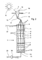
- the device 1 in particular represents a photo-optically operating bioreactor.
- the device 1 preferably has means for collecting light 2, in particular from the sun S, and / or preferably for the three-dimensional distribution of light 2 in the water or liquid medium 3 (FIG. here the algae suspension).
- the medium 3 is in particular a suspension or the like. Accordingly, the term "liquid” is to be understood in a broad sense, so that in particular suspensions, dispersions or other mixtures or substances with liquid phases or proportions are included.
- the medium 3 is preferably photoactive and / or biologically active.
- a photosynthesis or other light 2 requiring reaction take place.
- the medium 3 contains for this purpose a biologically active species, in particular algae, other bacteria or the like.
- the medium 3 is aqueous or contains water and / or strong light-scattering.
- an algal suspension is particularly preferably used as medium 3.
- the medium 3 contains an algae mixture culture, which preferably occurs at least in similar form in rivers, ponds or the like. Such mixed cultures are namely particularly resistant to environmental influences, diseases and / or other disorders.
- the device 1 is preferably used with algae or with an algae suspension as the medium 3, the following description is primarily focused on the algae growth induced by the induced light 2. however Accordingly, these statements also apply to other species or photo- or bioactive media 3.
- the device 1 or means for supplying or introducing light 2 preferably has or have optical fibers 4 (in particular glass fibers or acrylic fibers).
- optical fibers 4 in particular glass fibers or acrylic fibers.
- several or all of the fibers 4 end in different spatial regions, in particular at least partially in different depths and / or vertical planes, in the medium 3. This permits a three-dimensional distribution of the light 2 in the medium 3, as shown by way of example only schematically.
- the fibers 4 terminate at different levels within the medium 3. However, the fibers 4 may all end differently or irregularly.
- the fibers 4 Starting from a bundle (main bundle) 5 of fibers 4, in particular a branching or branching into individual bundles 6 and / or individual fibers 4, as in FIG Fig. 2 indicated by way of example.
- the fibers 4 preferably terminate individually, ie separately in the medium 3.
- several fibers 4 may end together in the medium 3, for example as a single bundle 5.
- the light emerges at least substantially or exclusively at the end of the respective fiber 4 and illuminates the medium 3 in the respective spatial region, as indicated by dashes in Fig. 2 indicated.
- the fibers 4 can also emit more or less light laterally along the respective fiber 4. Even so, an optimized three-dimensional distribution of light 2 in the medium 3 can take place. With appropriate design of the fibers 4, it is even possible that at least substantially the total light is already emitted laterally over the running in the medium 3 lengths of the respective fiber 4 and optionally only a relatively small proportion at the end of the respective fiber 4 in the medium third is emitted. In this case, the fibers 4 preferably run essentially over longer distances parallel to one another or, for example, coiled or meandering through the medium 3 and may possibly even all end in a plane or depth in the medium 3.
- the fibers 4 can dive loosely into the medium 3 or hang into it, optionally also as a bundle 5 or 6, which then branch in particular.
- the device 1 in particular lattice- or rod-like holders 7 in the medium 3, which are arranged in particular in different planes or depths to hold the fibers 4 or bundles 5, 6 or lead.
- the holders 7 form intermediate bottoms in a container or tank 8 with the medium 3 in order to allow the fibers 4 or bundles 5 or 6 to end in different spatial regions within the medium 3.
- the supply or introduction of the fibers 4 or bundle 5/6 is preferably carried out from above, in the embodiment by an upper bracket or cover 9 or the like.
- the fibers 4 or bundles 5/6 preferably extend at least substantially vertically from top to bottom in the medium 3. This is particularly advantageous when the density of the fibers 4 is greater than the density of the medium 3, so they do not float.
- the fibers 4 or bundles 5/6 may extend into the medium 3 from the bottom to the top and / or in some other way - for example transversely - or to guide them at least in sections.
- the fibers 4 are preferably made of plastic, glass or other material suitable for light conduction or structure.
- plastic, glass or other material suitable for light conduction or structure In particular, composite materials or composite structures, for example with coatings, can also be used.
- sunlight 2 is preferably used to illuminate the medium 3 or the algae, even if basically any other light can be used.
- the term "light” is preferably to be understood in a broad sense that not only visible light but, for example, alternatively or additionally also infrared light and / or ultraviolet light according to the medium 3 can be supplied.
- the energy supply via the fibers 4 of the medium 3 can also serve purposes other than the photosynthesis and / or stimulation of the biological growth and / or the conversion of carbon dioxide into biomass provided in the illustration example.
- the device 1 has a collecting device 10 for collecting light 2, in particular sunlight, as shown schematically.
- the collected sunlight or other light from another illumination device can then be passed through the fibers 4 or in particular a bundle 5 or 6 to the container or tank 8 with the medium 3, in particular with very low losses.
- leads of several 100 m are possible. This is very advantageous, especially in the case of a large amount of light, because correspondingly large areas, light-collecting devices or the like are required and / or take into account corresponding structural conditions must and / or can.
- the collecting device 10 has a dome-shaped cover or dome 14, a conical or funnel-shaped collector 15 and / or a coupler 16 for connecting the fibers 4 and / or for distributing the light 2 into the fibers 4.
- the collector 1 and the coupler 16 or all components form a structural unit.
- the dome 14 is preferably arranged on or on a roof 17, in particular a building, as in the FIG. 2 indicated. However, other facilities are possible.
- an alignment of the collecting device 10 or the dome 14 takes place towards a central position of the sun.
- the dome 14 is preferably hemispherical in shape. In particular, it has a diameter of about 20 to 100 cm, more preferably about 25 to 50 cm.
- the dome 14 is preferably formed from the inside reflective.
- the dome 14 is preferably highly translucent and in particular has a transmittance greater than 99%.
- the dome 14 is made of transparent plastic.
- the collector 15 preferably has an entrance diameter of about 20 to 100 cm, in particular about 25 to 50 cm. It preferably has a diameter on the exit side of about 3 to 15 cm, in particular about 5 to 10 cm.
- the light path in the collector 15 from the light entry side to the light exit side or to the coupler 16 is preferably tapered, in particular at an angle of at most 30 °, more preferably at most 20 ° and in particular substantially 10 °.
- the collector 15 is preferably made at least substantially of sheet metal. However, basically any other suitable material can be used.
- the collector 15 is formed on the inside highly reflective and in particular has a reflectance greater than 99%.
- the collector 15 is internally provided with a reflective coating or foil.
- the coupler 16 is designed in particular as a star coupler.
- the fibers 4 are preferably connected directly to the coupler 16, in particular melted thereto.
- the coupler 16 preferably closes off the collector 15 on the outlet side and / or adjoins the collector 15 on the outlet side.
- the coupler 16 is preferably conical or frusto-conical in shape and / or inserted inside the collector 15.
- the coupler 16 is preferably made of highly transparent material, in particular acrylic glass.
- the light 2 is preferably forwarded to the fibers 4 by utilizing the total reflection and distributed thereon.
- multiple collection devices 10 can be used to supply light 2 to common medium 4 or bundles 5 or 6 or separate fibers 4 or bundles 5/6, preferably in a common container or tank 8.
- the device 1 optionally has a device 11 for the introduction of gas, which contains in particular carbon dioxide or consists thereof.
- gas which contains in particular carbon dioxide or consists thereof.
- the device 11 in particular has a bottom, a sieve 12 or some other suitable introduction means for introducing or discharging the gas, in particular in the form of gas bubbles 13, into the medium 3, as in FIG Fig. 2 indicated schematically.
- the gas supply or -ein takes place in particular at the bottom and / or at a certain depth, preferably of at least 5 to 6 m, to allow a good exchange of gas or a good supply of the medium 3 and thus the algae with the gas.
- the gas above the medium 3 - in the illustrated example for example, above the cover 9 or within the container or tank 8 sucked and fed back through the device 11, so recirculated to a particularly good utilization or a particularly good degradation of the gas, especially of carbon dioxide.
- the introduction of the gas preferably takes place at a depth of about 3 to 50 m, preferably 5 to 10 m, into the medium 3.
- the screen 12 or the like can be used as needed.
- the container or tank 8 or the medium 3 is preferably a circulating device, such as a circulating pump, an agitator o. The like., Assigned. Thus, a sufficient and in particular growth-promoting movement of the medium 3 or the algae suspension can be ensured.
- the initial diameter of the gas bubbles 13 is, for example 0.1 to 10 .mu.m, preferably less than 1 .mu.m, in particular substantially 0.2 to 0.6 microns.
- Such small gas bubbles 13 can be made in particular by introduction in a corresponding depth, for example about 50 m or more, in the medium 3.
- the medium 3 can also be pressurized.
- the introduction of the gas takes place at a pressure of the medium 3 of about 50 to 800 kPa. More preferably, the pressure of the medium 3 at which the gas is introduced is at least about 500 kPa and more to form very small gas bubbles 13.
- the gas bubbles 13 Due to the small size of the gas bubbles 13, it is possible to stimulate these by direct exposure to light, in particular sunlight, to resonance absorption, so that the light is transported when ascending the gas bubbles 13 into the interior of the reactor or up through the medium 3.
- the exposure of the gas bubbles 13 can in particular be effected again via optical fibers 4 and / or in any other way.
- gas bubbles 13 can form resonators for the incident light 2.
- the resonance frequencies depend on the diameter of the gas bubbles 13.
- gas bubbles 13 with different diameters, in particular with a diameter spectrum covering the supplied light spectrum, are preferably produced.
- the photosynthesis can be imitated by means of a technical device.
- the proposed device 1 can also work or be referred to as a bioreactor.
- the algal suspension in the entire reactor volume, ie in the entire container 8 be illuminated by means of fiber technology.
- this takes place in that the fibers 4 end in different areas of space in the container 8 or branch, as based on the first Embodiment explained.
- the spatial distribution of the light 2 in the medium 3 can also be effected by means of gas bubbles 13, in particular by a mist of luminous bubbles, as explained with reference to the second embodiment.
- the IR fraction is separated from the sunlight, and can be used, for example, for other purposes, in particular for drying the biomass produced, such as algae, or the like.
- a lateral emission can also take place. This can be achieved in particular by correspondingly large curvature of the fibers 4. If necessary, the fibers 4 can accordingly also be strongly curved, in particular coiled, guided or run in the medium 3.
- the device 1 or its tank 8 is preferably designed such that the medium or water 3, in particular the algal suspension is such Wegleitbar that such a circulation takes place that the photosynthesis and / or algae growth is supported or will.
- Fig. 3 shows a schematic representation of another embodiment of the proposed arrangement 18 for the treatment of flue gas 20 or other raw gas. Only essential differences compared to already described embodiments and variants are explained below, the previous explanations, aspects and features in particular supplementary or apply accordingly.
- the assembly 18 may optionally or in parallel to a plurality of flue gas plants or generators 27, such as power plant units, combustion units, burners o. The like. To be connected, as in Fig. 3 indicated.
- the arrangement 18 then serves for the treatment, in particular cleaning, of the flue gas 20 emitted by the flue gas installations 27 or of another raw gas.
- the arrangement 18 optionally has a pre-treatment or pre-cleaning, which can act or work in particular in the manner of a cold trap.
- the arrangement 18 has at least one or more flue gas condensers 33 for condensing in particular higher-value hydrocarbons.
- the (two) capacitors 33 are connected in parallel and in particular are operated alternately.
- the condensate of the flue gas condensers 33 is preferably collected or stored in an optional reservoir 28.
- the reservoir 28 is fluidly connected to a device 1 for biodegradation of carbonaceous compounds and / or odoriferous substances, as already described above.
- the in Fig. 3 not shown condensate cleaned or treated by the device 1.
- Treated or purified water from the device 1 is preferably used for cleaning or for washing the capacitors 33.
- one capacitor 33 is cleaned while the other capacitor 33 is in operation and vice versa.
- the treated or purified water from the device 1 is in particular via in Fig. 3 schematically indicated valves, so either one of the two capacitors 33 fed and injected in particular in order to clean this.
- the cleaning water conducted through a condenser 33 is preferably also collected or stored in the reservoir 28 and / or cleaned or treated again by the device 1.
- the raw gas or flue gas 20 is preferably guided by the respective capacitor 33 meandering or in any other suitable manner.
- the condenser 33 is cooled in order to achieve extensive condensation of pollutants, higher-value hydrocarbons or the like.
- the above-described purification stage or condensation stage represents a pretreatment or pre-purification of the raw gas or flue gas 20.
- alkaline cleaning agents can be added to the water 3 or the algae suspension or the condensate.
- such or other cleaning agents are added to the reservoir 28.
- other constructive solutions are possible.
- the proposed arrangement 18 is preferably carried out in combination with the optional pretreatment a post or main treatment or main cleaning of the flue gas 20, more preferably by at least one additional flue gas scrubber 19 or 29 and / or by passing flue gas 20 or other exhaust air through a particular living species containing water 3 or an algal suspension.
- the arrangement 18 - in particular for main treatment or main cleaning - at least one, preferably a plurality of flue gas scrubber 29, wherein the preferably pretreated or pre-cleaned flue gas or raw gas passed through the water 3 or an algal suspension and thereby purified.
- the flue gas is introduced into a flue gas scrubber 29, preferably in the form of gas bubbles or as a gas bubble vortex and in particular collected again (above) and preferably derived.
- the flue gas is passed in succession through a plurality of flue gas scrubber 29. So it is preferably a multi-stage gas scrubbing or main treatment.
- 29 purified or derived gas is again introduced into the water 3 of the next flue gas scrubber 29 in a flue gas scrubber etc.
- the flue gas scrubbers 29 are thus flowed through serially or sequentially from the flue gas to be cleaned.
- other constructive solutions are possible.
- the flue gas scrubbers 29 are preferably connected to a common or own, in particular as already described constructed device 1 for biodegradation of carbonaceous compounds and / or odoriferous substances from the emitted smoke water. Especially the flue gas scrubbers 29 are connected in parallel to the device 1 and the water cycle. However, the flue gas scrubbers 29 may also be connected in series to the device 1 or the water cycle.
- the term "water cycle” preferably also includes a circulation of the algal suspension or the like.
- an algal suspension or water 3 is used with any other biological species in the pretreatment and the main treatment in a separate circuit.
- the two circuits can also be formed by a common circuit, in particular with a common or a plurality of common, for example, in parallel or sequentially flowed through devices 1.
- the light supply takes place in the pretreatment and / or main treatment associated with device 1 preferably by lateral irradiation, as indicated by corresponding arrows in Fig. 3 indicated.
- Fig. 3 the light supply takes place in the pretreatment and / or main treatment associated with device 1 preferably by lateral irradiation, as indicated by corresponding arrows in Fig. 3 indicated.
- other constructive solutions as already in particular with reference to Fig. 2 explained, possible.
- the living species or algae are at least partially removed from the circulating water 3. This can be done for example by filtering or other separation. This is exemplary for the cycle of the main cleaning in Fig. 3 indicated.
- the water 3 or the algae suspension or a partial flow thereof is here at least on demand, discontinuously or continuously by a separation device, such as a filter device 30 can be conducted.
- a separation device such as a filter device 30 can be conducted.
- other constructive or procedural solutions are possible here.
- the purified gas is preferably passed through a fan 31 to an optional chimney 32 or other outlet o. Alternatively or additionally, another aftertreatment can take place.
- the flue gas or raw gas or the exhaust air is pumped or sucked by means of the fan 31 through the pretreatment and main treatment or, the capacitors 33 and / or flue gas scrubber 29.
- the fan 31 is pumped or sucked by means of the fan 31 through the pretreatment and main treatment or, the capacitors 33 and / or flue gas scrubber 29.
- other constructive solutions are possible.
- a plurality of fans instead of a common or single fan 31, a plurality of fans o. The like. Be used.
- individual flue gas scrubbers 19 and 29 are preferably individually switched off or shut off, in particular for cleaning or other maintenance purposes.
- the algae can also be used very well for biodegradation of odoriferous substances in manure.
- the manure is biologically cleaned or treated by algae under the action of light.
- odoriferous substances in the manure are biodegraded by means of algae under the action of light. This can be done, for example, by introducing the liquid manure into the device 1 and / or adding or mixing it with algae or an algae suspension or by adding or adding it to an algae suspension.
- the algae at least very largely remove, bind and / or degrade the odoriferous substances in a very short time, so that after a very short time quasi no odoriferous substance is present, thus treated manure without special measures, in particular open, further processed, stored or, for example, applied to a field.
Landscapes
- Engineering & Computer Science (AREA)
- Chemical & Material Sciences (AREA)
- Life Sciences & Earth Sciences (AREA)
- Environmental & Geological Engineering (AREA)
- Chemical Kinetics & Catalysis (AREA)
- Analytical Chemistry (AREA)
- Health & Medical Sciences (AREA)
- General Chemical & Material Sciences (AREA)
- Biomedical Technology (AREA)
- Oil, Petroleum & Natural Gas (AREA)
- Biotechnology (AREA)
- Molecular Biology (AREA)
- Botany (AREA)
- Biodiversity & Conservation Biology (AREA)
- Microbiology (AREA)
- Hydrology & Water Resources (AREA)
- Water Supply & Treatment (AREA)
- Organic Chemistry (AREA)
- Treating Waste Gases (AREA)
- Apparatus Associated With Microorganisms And Enzymes (AREA)
Applications Claiming Priority (2)
| Application Number | Priority Date | Filing Date | Title |
|---|---|---|---|
| DE102009005176 | 2009-01-15 | ||
| DE102009006238 | 2009-01-27 |
Publications (2)
| Publication Number | Publication Date |
|---|---|
| EP2208521A2 true EP2208521A2 (fr) | 2010-07-21 |
| EP2208521A3 EP2208521A3 (fr) | 2010-10-13 |
Family
ID=42077631
Family Applications (1)
| Application Number | Title | Priority Date | Filing Date |
|---|---|---|---|
| EP10000340A Withdrawn EP2208521A3 (fr) | 2009-01-15 | 2010-01-15 | Dispositif et procédé destinés au traitement d'eau non potable |
Country Status (1)
| Country | Link |
|---|---|
| EP (1) | EP2208521A3 (fr) |
Cited By (4)
| Publication number | Priority date | Publication date | Assignee | Title |
|---|---|---|---|---|
| WO2018056804A1 (fr) * | 2016-09-26 | 2018-03-29 | Van Der Linden Mattheus Antonius Cornelis | Appareil et procédé de traitement d'air par des algues |
| WO2020130901A1 (fr) * | 2018-12-22 | 2020-06-25 | Mats Hedman | Procédé et agencement pour réduire le dioxyde de carbone dans es gaz d'échappement de combustion |
| CN113365719A (zh) * | 2018-12-22 | 2021-09-07 | 绿化石技术有限公司 | 用于减少燃烧废气中二氧化碳的方法和装置 |
| US11413576B2 (en) * | 2019-06-12 | 2022-08-16 | Cheng-Jen Lin | Method for treating gas |
Citations (2)
| Publication number | Priority date | Publication date | Assignee | Title |
|---|---|---|---|---|
| DE202008004029U1 (de) | 2008-03-20 | 2008-05-29 | Universität Duisburg-Essen | Anordnung zur Lichtleitung |
| DE102007050484A1 (de) | 2007-05-07 | 2008-11-13 | Universität Duisburg-Essen | Anordnung und Verfahren zur dreidimensionalen Verteilung von Licht in einem flüssigen Medium |
Family Cites Families (8)
| Publication number | Priority date | Publication date | Assignee | Title |
|---|---|---|---|---|
| US3999329A (en) * | 1974-05-13 | 1976-12-28 | Joseph Jean Pierre Brais | Apparatus and method for treating flue gas and passing treated constituents into greenhouse |
| DE3707575A1 (de) * | 1987-03-10 | 1988-09-22 | Arasin Gmbh | Verfahren und vorrichtung zur reinigung von abluft oder abgasen |
| NL9002661A (nl) * | 1990-12-04 | 1992-07-01 | Pacques Bv | Werkwijze voor de verwijdering van h2s uit gas. |
| DE4444191C1 (de) * | 1994-12-12 | 1996-06-05 | Melkonian Ezekian Michael Prof | Verfahren zur Abreicherung oder Entfernung von Kohlendioxid aus Abgasen |
| US6648949B1 (en) * | 2001-11-28 | 2003-11-18 | The United States Of America As Represented By The United States Department Of Energy | System for small particle and CO2 removal from flue gas using an improved chimney or stack |
| CN100418614C (zh) * | 2003-04-17 | 2008-09-17 | 国际壳牌研究有限公司 | 从气流中脱除h2s和硫醇的方法 |
| WO2005123237A2 (fr) * | 2004-05-14 | 2005-12-29 | Eco/Technologies, Llc | Procede et systeme pour capturer des emissions de carbone d'un bruleur/d'une chaudiere |
| ES2265289B1 (es) * | 2005-07-19 | 2007-12-16 | Aplicacions Biotecnologiques En Salut Alimentacio I Medi Ambient, Bionatur, S.L. | Un metodo para reducir la proporcion de agentes contaminantes en gases de combustion industriales, y procedimiento para preparar una composicion util para el metodo. |
-
2010
- 2010-01-15 EP EP10000340A patent/EP2208521A3/fr not_active Withdrawn
Patent Citations (2)
| Publication number | Priority date | Publication date | Assignee | Title |
|---|---|---|---|---|
| DE102007050484A1 (de) | 2007-05-07 | 2008-11-13 | Universität Duisburg-Essen | Anordnung und Verfahren zur dreidimensionalen Verteilung von Licht in einem flüssigen Medium |
| DE202008004029U1 (de) | 2008-03-20 | 2008-05-29 | Universität Duisburg-Essen | Anordnung zur Lichtleitung |
Cited By (5)
| Publication number | Priority date | Publication date | Assignee | Title |
|---|---|---|---|---|
| WO2018056804A1 (fr) * | 2016-09-26 | 2018-03-29 | Van Der Linden Mattheus Antonius Cornelis | Appareil et procédé de traitement d'air par des algues |
| WO2020130901A1 (fr) * | 2018-12-22 | 2020-06-25 | Mats Hedman | Procédé et agencement pour réduire le dioxyde de carbone dans es gaz d'échappement de combustion |
| CN113365719A (zh) * | 2018-12-22 | 2021-09-07 | 绿化石技术有限公司 | 用于减少燃烧废气中二氧化碳的方法和装置 |
| US11484835B2 (en) | 2018-12-22 | 2022-11-01 | Green Fossil Technologies AB | Process and arrangement for reducing carbon dioxide in combustion exhaust gases |
| US11413576B2 (en) * | 2019-06-12 | 2022-08-16 | Cheng-Jen Lin | Method for treating gas |
Also Published As
| Publication number | Publication date |
|---|---|
| EP2208521A3 (fr) | 2010-10-13 |
Similar Documents
| Publication | Publication Date | Title |
|---|---|---|
| EP3411087B1 (fr) | Dispositif d'épuration de l'air | |
| DD240028A5 (de) | Verfahren und vorrichtung zum reinigen styrolbelasteter abluft | |
| EP0138890B1 (fr) | Installation pour le traitement des gaz de combustion | |
| DE3427448A1 (de) | Verfahren und vorrichtung zur biologischen abwasserreinigung | |
| DE102007050484A1 (de) | Anordnung und Verfahren zur dreidimensionalen Verteilung von Licht in einem flüssigen Medium | |
| EP2208521A2 (fr) | Dispositif et procédé destinés au traitement d'eau non potable | |
| DE60007611T2 (de) | Trockner mit mechanischer verdichtung des dampfes, anlage und verfahren zur chemischen reinigung des dampfes | |
| DE3620728A1 (de) | Vorrichtung und verfahren zur biologischen abluft- und abwasserreinigung | |
| DE102007042284A1 (de) | Rezirkulationshaube | |
| DE3835230C2 (de) | Verfahren zur Energiegewinnung durch Müllentgasung und Müllentgasungsanlage | |
| WO2010139377A1 (fr) | Tour de lavage et dispositif d'épuration de gaz de combustion y afférent | |
| DE3709269C2 (de) | Vorrichtung zum Entfernen organischer Stoffe aus Abluft | |
| DE10110519B4 (de) | Biofilter | |
| EP2385102A2 (fr) | Procédé de fonctionnement d'un réacteur de biomasse et réacteur de biomasse | |
| WO2022079109A1 (fr) | Photobioréacteur, en particulier pour la production de microorganismes tels que des microalgues | |
| DE102009033573B4 (de) | Verfahren und Einrichtung zur biologischen und ökologisch verträglichen Umsetzung von CO2 in Kohlenstoff und Sauerstoff | |
| DE19808895C2 (de) | Verfahren zur Veränderung der Konzentration von Inhaltsstoffen in einem Gas, insbesondere Raumluft, und Vorrichtung zur Durchführung dieses Verfahrens | |
| DE102012009234A1 (de) | Vorrichtung und Verfahren zur biologischen Gasreinigung | |
| DE102007012745A1 (de) | Verfahren und System der photosynthetischen Reaktion von Algen und Mikroben | |
| EP0167696A1 (fr) | Appareil pour la production de biogaz | |
| DE102010017097A1 (de) | Trocknungsanlage für Biomasse und/oder Schlämme und Verfahren hierzu | |
| DE202008004029U1 (de) | Anordnung zur Lichtleitung | |
| DE19716169C2 (de) | Verfahren zur Reduzierung des Algen- und Nährstoffgehalts eines Gewässers und Vorrichtung zur Durchführung dieses Verfahrens | |
| DE102019007167A1 (de) | Emerser Bioreaktor | |
| EP0885564B1 (fr) | Installation pour le traitement d'eau et utilisation de cette eau |
Legal Events
| Date | Code | Title | Description |
|---|---|---|---|
| PUAI | Public reference made under article 153(3) epc to a published international application that has entered the european phase |
Free format text: ORIGINAL CODE: 0009012 |
|
| AK | Designated contracting states |
Kind code of ref document: A2 Designated state(s): AT BE BG CH CY CZ DE DK EE ES FI FR GB GR HR HU IE IS IT LI LT LU LV MC MK MT NL NO PL PT RO SE SI SK SM TR |
|
| AX | Request for extension of the european patent |
Extension state: AL BA RS |
|
| PUAL | Search report despatched |
Free format text: ORIGINAL CODE: 0009013 |
|
| AK | Designated contracting states |
Kind code of ref document: A3 Designated state(s): AT BE BG CH CY CZ DE DK EE ES FI FR GB GR HR HU IE IS IT LI LT LU LV MC MK MT NL NO PL PT RO SE SI SK SM TR |
|
| AX | Request for extension of the european patent |
Extension state: AL BA RS |
|
| 17P | Request for examination filed |
Effective date: 20110412 |
|
| STAA | Information on the status of an ep patent application or granted ep patent |
Free format text: STATUS: THE APPLICATION IS DEEMED TO BE WITHDRAWN |
|
| 18D | Application deemed to be withdrawn |
Effective date: 20130801 |