EP2208896A1 - douille d'ancrage - Google Patents
douille d'ancrage Download PDFInfo
- Publication number
- EP2208896A1 EP2208896A1 EP10401003A EP10401003A EP2208896A1 EP 2208896 A1 EP2208896 A1 EP 2208896A1 EP 10401003 A EP10401003 A EP 10401003A EP 10401003 A EP10401003 A EP 10401003A EP 2208896 A1 EP2208896 A1 EP 2208896A1
- Authority
- EP
- European Patent Office
- Prior art keywords
- joint
- anchor sleeve
- anchor
- sleeve
- groove
- Prior art date
- Legal status (The legal status is an assumption and is not a legal conclusion. Google has not performed a legal analysis and makes no representation as to the accuracy of the status listed.)
- Withdrawn
Links
- 238000004873 anchoring Methods 0.000 claims description 9
- 230000002093 peripheral effect Effects 0.000 description 4
- 239000000126 substance Substances 0.000 description 4
- 230000037431 insertion Effects 0.000 description 3
- 238000003780 insertion Methods 0.000 description 3
- 239000000203 mixture Substances 0.000 description 3
- 239000004570 mortar (masonry) Substances 0.000 description 3
- 230000006978 adaptation Effects 0.000 description 2
- 239000000853 adhesive Substances 0.000 description 2
- 230000001070 adhesive effect Effects 0.000 description 2
- 230000015572 biosynthetic process Effects 0.000 description 2
- 230000007423 decrease Effects 0.000 description 2
- 239000002689 soil Substances 0.000 description 2
- 150000001875 compounds Chemical class 0.000 description 1
- 230000006835 compression Effects 0.000 description 1
- 238000007906 compression Methods 0.000 description 1
- 238000001746 injection moulding Methods 0.000 description 1
- 210000001503 joint Anatomy 0.000 description 1
- 229920005989 resin Polymers 0.000 description 1
- 239000011347 resin Substances 0.000 description 1
- 229920003002 synthetic resin Polymers 0.000 description 1
- 239000000057 synthetic resin Substances 0.000 description 1
Images
Classifications
-
- F—MECHANICAL ENGINEERING; LIGHTING; HEATING; WEAPONS; BLASTING
- F16—ENGINEERING ELEMENTS AND UNITS; GENERAL MEASURES FOR PRODUCING AND MAINTAINING EFFECTIVE FUNCTIONING OF MACHINES OR INSTALLATIONS; THERMAL INSULATION IN GENERAL
- F16B—DEVICES FOR FASTENING OR SECURING CONSTRUCTIONAL ELEMENTS OR MACHINE PARTS TOGETHER, e.g. NAILS, BOLTS, CIRCLIPS, CLAMPS, CLIPS OR WEDGES; JOINTS OR JOINTING
- F16B13/00—Dowels or other devices fastened in walls or the like by inserting them in holes made therein for that purpose
- F16B13/14—Non-metallic plugs or sleeves; Use of liquid, loose solid or kneadable material therefor
- F16B13/141—Fixing plugs in holes by the use of settable material
- F16B13/146—Fixing plugs in holes by the use of settable material with a bag-shaped envelope or a tubular sleeve closed at one end, e.g. with a sieve-like sleeve, or with an expandable sheath
Definitions
- the invention relates to an anchor sleeve for the chemical anchoring of an anchor rod in a borehole with the features of the preamble of claim 1.
- Chemical anchoring means the attachment of an anchor rod by means of a hardening mass, for example a one- or multi-component adhesive or mortar.
- the anchor rod can be for example a threaded rod, a so-called Dywidag rod or a special anchor rod with a number of truncated cones arranged in line.
- anchor sleeves are known which have outlet openings for the curing mass. Your peripheral wall is for example perforated or sieve-like.
- the anchor sleeve is inserted into the borehole and it is introduced the hardening mass in the anchor sleeve.
- anchor rod is inserted into the anchor sleeve and displaces the hardening mass so that it emerges through the outlet openings and holds the anchor rod after curing in the borehole.
- An example of such an anchor sleeve discloses the utility model DE 296 06 215 U1 ,
- the patent discloses CH 669 017 A5 a perforated and thus outlet openings having film. According to the bore diameter, a piece is separated from the film and rolled into a tube with edges of the film overlapping each other and connected to a push-button type closure.
- the object of the invention is to propose a structurally differently designed anchor sleeve, which adapts to different diameters.
- the anchor sleeve according to the invention has a longitudinally extending joint, ie a gap, wherein the joint can also extend at an angle to the longitudinal direction, for example helically or wavy, meandering or zigzag-shaped.
- the anchor sleeve can be particularly elastically compress to a smaller diameter or expand to a larger diameter.
- the joint may for example be a butt joint, ie mutually facing joint edges of the anchor sleeve are located on a common imaginary cylindrical surface, wherein they have a more or less large distance from each other depending on the diameter or abut each other. An overlap of the joint edges is possible, with the overlap increases with smaller diameter.
- the anchor sleeve has a joint bridging, which bridges the joint.
- the joint bridging covers the joint of the anchor sleeve inside and / or outside.
- the joint bridging may have outlet openings for the hardening mass, for example sieve-like or perforated. Also, a closed joint bridging without outlets is possible.
- the joint bridging prevents a free escape of the hardenable mass from the anchor sleeve through the joint. A leakage of the mass in the region of the joint is only possible through the outlet openings of the joint bridging, provided that the joint bridging has outlet openings.
- the joint bridging is variable in length transversely to the joint to adapt to the size of the joint and thus to adapt to the diameter of the anchor sleeve.
- the joint bridging can be limp or elastic and / or plastically deformable and / or stretchable.
- An embodiment of the invention provides for a folding of the joint bridging for adaptation to different joint widths.
- an embodiment of the invention provides a bottom at one end of the anchor sleeve.
- the joint of the anchor sleeve continues into the ground.
- the joint has the shape of a circular sector.
- Another possibility for diameter adjustment is the formation of the soil as a scale overlapping segments whose overlap increases as the diameter decreases and vice versa.
- the segments of the soil are not per se circle segments, but for example, circular sectors or strips or have a different shape.
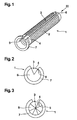
- anchor sleeve 1 is used for chemical anchoring, ie for attachment of an anchor rod, not shown, for example, a threaded rod, in a borehole with a hardening mass.
- the curing composition is for example a one- or multi-component adhesive or resin or other mortar.
- the anchor sleeve 1 is an integrally made by injection molding of plastic, tubular member whose peripheral wall perforated, for example, is sieve-like and thereby has outlet openings 2 for the curable composition. In the circumferential direction, the anchor sleeve 1 is not completely closed, but has a longitudinally extending, continuous joint 3, so that the anchor sleeve 1 is elastically compressible or expandable to accommodate different diameters.
- the joint 3 is bridged by a film-like joint bridging 4 and is therefore always closed, even if joint edges have a distance from each other.
- the joint bridging 4 has a fold 5, so that it is variable in length transversely to the joint 3 for adaptation to different diameters of the anchor sleeve 1, the different widths of the joint 3 condition.
- the joint bridging 4, like the peripheral wall of the anchor sleeve 1 has a perforation for the formation of outlet openings for the hardenable mass.
- the anchor sleeve 1 has a bottom 6 (see FIG. 2 ), on the other, here as the rear designated end, the anchor sleeve 1 has an outwardly projecting flange 7.
- the joint 3 continues into the bottom 6 and has in the bottom 6 in the form of a circular sector.
- the flange 7 limits an insertion depth of the anchor sleeve 1 in a borehole.
- the anchor sleeve 1 For chemical anchoring of an anchor rod, not shown here, the anchor sleeve 1 is inserted with its front, the bottom 6 having the end in front of a not shown well bore until the flange 7 rests against a borehole mouth. Subsequently, a curable composition, for example a synthetic resin mortar, is injected through the open, rear end into the anchor sleeve 1 and then the anchor rod is inserted into the anchor sleeve 1. The anchor rod displaces the hardenable mass so that it exits through the outlet openings 2 in the peripheral wall of the anchor sleeve 1 and in the joint bridging 4 and anchors after anchoring the anchor rod in the borehole, i. holds.
- a curable composition for example a synthetic resin mortar
- FIG. 3 shows a modified embodiment of the bottom 6 of the anchor sleeve 1.
- the bottom 6 circular sector-shaped segments which overlap each other. The overlap increases upon compression of the anchor sleeve 1 to a smaller diameter and decreases when expanding the anchor sleeve 1 to a larger diameter.
- the in FIG. 3 illustrated anchor sleeve 1 is the same as that made Figures 1 and 2 and works the same way. For explanation of FIG. 3 the remarks become too Figures 1 and 2 referenced.
Landscapes
- Engineering & Computer Science (AREA)
- General Engineering & Computer Science (AREA)
- Mechanical Engineering (AREA)
- Piles And Underground Anchors (AREA)
- Dowels (AREA)
Applications Claiming Priority (1)
| Application Number | Priority Date | Filing Date | Title |
|---|---|---|---|
| DE102009004921A DE102009004921A1 (de) | 2009-01-16 | 2009-01-16 | Ankerhülse |
Publications (1)
| Publication Number | Publication Date |
|---|---|
| EP2208896A1 true EP2208896A1 (fr) | 2010-07-21 |
Family
ID=42120308
Family Applications (1)
| Application Number | Title | Priority Date | Filing Date |
|---|---|---|---|
| EP10401003A Withdrawn EP2208896A1 (fr) | 2009-01-16 | 2010-01-11 | douille d'ancrage |
Country Status (2)
| Country | Link |
|---|---|
| EP (1) | EP2208896A1 (fr) |
| DE (1) | DE102009004921A1 (fr) |
Cited By (4)
| Publication number | Priority date | Publication date | Assignee | Title |
|---|---|---|---|---|
| WO2011127871A1 (fr) * | 2010-04-16 | 2011-10-20 | Ecoraw, S.R.O. | Fixation à expansion |
| WO2012142982A1 (fr) | 2011-04-18 | 2012-10-26 | Ecoraw.Cz S.R.O | Ancre pour systèmes d'isolation thermique de bâtiments et procédé d'ancrage dans des systèmes d'isolation thermique de bâtiments |
| CZ306878B6 (cs) * | 2011-09-13 | 2017-08-23 | Ecoraw.Rdp S.R.O. | Kotvicí sestava tepelně - izolačního stavebního kontaktního i bezkontaktního systému a tvarovací přípravek a montážní přípravek pro úpravu kotvicí sestavy |
| EP4491890A1 (fr) | 2023-07-11 | 2025-01-15 | TOX-Dübel-Technik GmbH | Manchon d'ancrage étanche |
Citations (3)
| Publication number | Priority date | Publication date | Assignee | Title |
|---|---|---|---|---|
| DE3120809A1 (de) * | 1981-05-25 | 1982-12-16 | Hilti AG, 9494 Schaan | Ankerbolzen mit zylindrischem bolzenkoerper |
| US5137395A (en) * | 1989-08-02 | 1992-08-11 | Ingersoll-Rand Company | Dynamic earth anchor, and a sleeve therefor |
| GB2284032A (en) * | 1993-11-06 | 1995-05-24 | Longleys | Bolt anchoring device |
Family Cites Families (6)
| Publication number | Priority date | Publication date | Assignee | Title |
|---|---|---|---|---|
| DE552294C (de) * | 1926-07-24 | 1932-06-13 | John Joseph Rawlings | Mauerduebelhuelse |
| DE3426174A1 (de) * | 1984-07-16 | 1986-01-23 | Hilti Ag, Schaan | Siebhuelse zur aufnahme von mittels aushaertender massen befestigbaren verankerungselementen |
| DE3515137A1 (de) | 1985-04-26 | 1986-11-06 | Hilti Ag, Schaan | Aufnahmehuelse fuer befestigungselemente |
| DE29606215U1 (de) | 1996-04-04 | 1996-06-13 | Upat GmbH & Co., 79312 Emmendingen | Dübel mit siebartiger Hülse |
| DE19855139A1 (de) * | 1998-11-30 | 2000-05-31 | Fischer Artur Werke Gmbh | Spreizdübel |
| DE20105013U1 (de) * | 2001-03-22 | 2002-08-01 | fischerwerke Artur Fischer GmbH & Co. KG, 72178 Waldachtal | Ankerhülse zur Injektionsbefestigung |
-
2009
- 2009-01-16 DE DE102009004921A patent/DE102009004921A1/de not_active Withdrawn
-
2010
- 2010-01-11 EP EP10401003A patent/EP2208896A1/fr not_active Withdrawn
Patent Citations (3)
| Publication number | Priority date | Publication date | Assignee | Title |
|---|---|---|---|---|
| DE3120809A1 (de) * | 1981-05-25 | 1982-12-16 | Hilti AG, 9494 Schaan | Ankerbolzen mit zylindrischem bolzenkoerper |
| US5137395A (en) * | 1989-08-02 | 1992-08-11 | Ingersoll-Rand Company | Dynamic earth anchor, and a sleeve therefor |
| GB2284032A (en) * | 1993-11-06 | 1995-05-24 | Longleys | Bolt anchoring device |
Cited By (6)
| Publication number | Priority date | Publication date | Assignee | Title |
|---|---|---|---|---|
| WO2011127871A1 (fr) * | 2010-04-16 | 2011-10-20 | Ecoraw, S.R.O. | Fixation à expansion |
| WO2012142982A1 (fr) | 2011-04-18 | 2012-10-26 | Ecoraw.Cz S.R.O | Ancre pour systèmes d'isolation thermique de bâtiments et procédé d'ancrage dans des systèmes d'isolation thermique de bâtiments |
| CZ308391B6 (cs) * | 2011-04-18 | 2020-07-15 | Ecoraw.Rdp S.R.O. | Kotva pro tepelně izolační stavební systémy a způsob jejího ukotvení v tepelně izolačních stavebních systémech |
| CZ306878B6 (cs) * | 2011-09-13 | 2017-08-23 | Ecoraw.Rdp S.R.O. | Kotvicí sestava tepelně - izolačního stavebního kontaktního i bezkontaktního systému a tvarovací přípravek a montážní přípravek pro úpravu kotvicí sestavy |
| EP4491890A1 (fr) | 2023-07-11 | 2025-01-15 | TOX-Dübel-Technik GmbH | Manchon d'ancrage étanche |
| DE102023118268A1 (de) | 2023-07-11 | 2025-01-16 | TOX-Dübel-Technik GmbH | Abdichtende Ankerhülse |
Also Published As
| Publication number | Publication date |
|---|---|
| DE102009004921A1 (de) | 2010-07-22 |
Similar Documents
| Publication | Publication Date | Title |
|---|---|---|
| DE4107790C1 (fr) | ||
| EP1183475B1 (fr) | Cheville destinee a etre fixee a des materiaux de construction creux et solides | |
| EP1984632B1 (fr) | Cheville expansible | |
| EP1135618A1 (fr) | Cheville a expansion | |
| DE2901066B1 (de) | Spreizdübel | |
| EP2513498B1 (fr) | Douille d'ancrage | |
| DE102009004921A1 (de) | Ankerhülse | |
| DE20105013U1 (de) | Ankerhülse zur Injektionsbefestigung | |
| DE102004015646A1 (de) | Spreizdübel | |
| DE4004207C2 (de) | Befestigungsvorrichtung | |
| EP0421104B1 (fr) | Cheville expansible et méthode pour sa fabrication | |
| DE102005000185A1 (de) | Befestigungselement für die Befestigung von Dämmstoffplatten an einem Untergrund | |
| DE102012111220A1 (de) | Spreizdübel | |
| DE102004010727A1 (de) | Spreizanker | |
| EP2025952B1 (fr) | Piton à expansion | |
| EP1970575A2 (fr) | Piton à expansion pour mur à double paroi | |
| EP2148100A1 (fr) | Elément d'ancrage | |
| DE102004052184A1 (de) | Nageldübel | |
| DE19859220A1 (de) | Spreizdübel | |
| DE102006023024A1 (de) | Dübel | |
| EP4261446B1 (fr) | Dispositif de fixation, ensemble comprenant un dispositif de fixation et procédé de fabrication d'un dispositif de fixation | |
| EP2230409A1 (fr) | Douille d'ancrage | |
| EP2072836B1 (fr) | Elément de protection | |
| DE2947751A1 (de) | Hohlraumduebel | |
| AT501606B1 (de) | Spreizdübel |
Legal Events
| Date | Code | Title | Description |
|---|---|---|---|
| PUAI | Public reference made under article 153(3) epc to a published international application that has entered the european phase |
Free format text: ORIGINAL CODE: 0009012 |
|
| AK | Designated contracting states |
Kind code of ref document: A1 Designated state(s): AT BE BG CH CY CZ DE DK EE ES FI FR GB GR HR HU IE IS IT LI LT LU LV MC MK MT NL NO PL PT RO SE SI SK SM TR |
|
| AX | Request for extension of the european patent |
Extension state: AL BA RS |
|
| STAA | Information on the status of an ep patent application or granted ep patent |
Free format text: STATUS: THE APPLICATION IS DEEMED TO BE WITHDRAWN |
|
| 18D | Application deemed to be withdrawn |
Effective date: 20100722 |