EP4261446B1 - Dispositif de fixation, ensemble comprenant un dispositif de fixation et procédé de fabrication d'un dispositif de fixation - Google Patents
Dispositif de fixation, ensemble comprenant un dispositif de fixation et procédé de fabrication d'un dispositif de fixation Download PDFInfo
- Publication number
- EP4261446B1 EP4261446B1 EP23167121.5A EP23167121A EP4261446B1 EP 4261446 B1 EP4261446 B1 EP 4261446B1 EP 23167121 A EP23167121 A EP 23167121A EP 4261446 B1 EP4261446 B1 EP 4261446B1
- Authority
- EP
- European Patent Office
- Prior art keywords
- positioning component
- projection
- sliding nut
- fastening device
- opening
- Prior art date
- Legal status (The legal status is an assumption and is not a legal conclusion. Google has not performed a legal analysis and makes no representation as to the accuracy of the status listed.)
- Active
Links
Images


Classifications
-
- F—MECHANICAL ENGINEERING; LIGHTING; HEATING; WEAPONS; BLASTING
- F16—ENGINEERING ELEMENTS AND UNITS; GENERAL MEASURES FOR PRODUCING AND MAINTAINING EFFECTIVE FUNCTIONING OF MACHINES OR INSTALLATIONS; THERMAL INSULATION IN GENERAL
- F16L—PIPES; JOINTS OR FITTINGS FOR PIPES; SUPPORTS FOR PIPES, CABLES OR PROTECTIVE TUBING; MEANS FOR THERMAL INSULATION IN GENERAL
- F16L3/00—Supports for pipes, cables or protective tubing, e.g. hangers, holders, clamps, cleats, clips, brackets
- F16L3/24—Supports for pipes, cables or protective tubing, e.g. hangers, holders, clamps, cleats, clips, brackets with special member for attachment to profiled girders
- F16L3/243—Supports for pipes, cables or protective tubing, e.g. hangers, holders, clamps, cleats, clips, brackets with special member for attachment to profiled girders the special member being inserted in the profiled girder
- F16L3/2431—Supports for pipes, cables or protective tubing, e.g. hangers, holders, clamps, cleats, clips, brackets with special member for attachment to profiled girders the special member being inserted in the profiled girder the special member being inserted and subsequently rotated to a limited extent
-
- F—MECHANICAL ENGINEERING; LIGHTING; HEATING; WEAPONS; BLASTING
- F16—ENGINEERING ELEMENTS AND UNITS; GENERAL MEASURES FOR PRODUCING AND MAINTAINING EFFECTIVE FUNCTIONING OF MACHINES OR INSTALLATIONS; THERMAL INSULATION IN GENERAL
- F16B—DEVICES FOR FASTENING OR SECURING CONSTRUCTIONAL ELEMENTS OR MACHINE PARTS TOGETHER, e.g. NAILS, BOLTS, CIRCLIPS, CLAMPS, CLIPS OR WEDGES; JOINTS OR JOINTING
- F16B37/00—Nuts or like thread-engaging members
- F16B37/04—Devices for fastening nuts to surfaces, e.g. sheets, plates
- F16B37/044—Nut cages
-
- F—MECHANICAL ENGINEERING; LIGHTING; HEATING; WEAPONS; BLASTING
- F16—ENGINEERING ELEMENTS AND UNITS; GENERAL MEASURES FOR PRODUCING AND MAINTAINING EFFECTIVE FUNCTIONING OF MACHINES OR INSTALLATIONS; THERMAL INSULATION IN GENERAL
- F16B—DEVICES FOR FASTENING OR SECURING CONSTRUCTIONAL ELEMENTS OR MACHINE PARTS TOGETHER, e.g. NAILS, BOLTS, CIRCLIPS, CLAMPS, CLIPS OR WEDGES; JOINTS OR JOINTING
- F16B37/00—Nuts or like thread-engaging members
- F16B37/04—Devices for fastening nuts to surfaces, e.g. sheets, plates
- F16B37/045—Devices for fastening nuts to surfaces, e.g. sheets, plates specially adapted for fastening in channels, e.g. sliding bolts, channel nuts
- F16B37/046—Devices for fastening nuts to surfaces, e.g. sheets, plates specially adapted for fastening in channels, e.g. sliding bolts, channel nuts with resilient means for urging the nut inside the channel
-
- F—MECHANICAL ENGINEERING; LIGHTING; HEATING; WEAPONS; BLASTING
- F16—ENGINEERING ELEMENTS AND UNITS; GENERAL MEASURES FOR PRODUCING AND MAINTAINING EFFECTIVE FUNCTIONING OF MACHINES OR INSTALLATIONS; THERMAL INSULATION IN GENERAL
- F16B—DEVICES FOR FASTENING OR SECURING CONSTRUCTIONAL ELEMENTS OR MACHINE PARTS TOGETHER, e.g. NAILS, BOLTS, CIRCLIPS, CLAMPS, CLIPS OR WEDGES; JOINTS OR JOINTING
- F16B7/00—Connections of rods or tubes, e.g. of non-circular section, mutually, including resilient connections
- F16B7/18—Connections of rods or tubes, e.g. of non-circular section, mutually, including resilient connections using screw-thread elements
- F16B7/187—Connections of rods or tubes, e.g. of non-circular section, mutually, including resilient connections using screw-thread elements with sliding nuts or other additional connecting members for joining profiles provided with grooves or channels
Definitions
- the invention relates to a fastening device for retaining rails with at least partially C-shaped cross-section, with a sliding nut, a retaining disk and a positioning component, wherein the positioning component engages around the sliding nut at least partially and the positioning component holds the retaining disk at a distance from the sliding nut.
- the fastening device for retaining rails with a C-shaped cross-section.
- the fastening device has a sliding nut for insertion into the retaining rail with a C-shaped cross-section and a retaining disk that is placed on the opening in the retaining rail.
- the retaining disk and the sliding nut are held relative to one another by means of a positioning component.
- the retaining disk has a central through-opening into which, for example, a screw is screwed. The thread of the screw then engages in a threaded opening in the sliding nut. If the screw is then tightened, the sliding nut is pressed from the inside of the retaining rail against the sections that border the opening in the retaining rail.
- the retaining disk is pressed from the opposite side against the sections of the retaining rail that delimit the opening.
- the fastening nut can be easily moved along the retaining rail by loosening the screw.
- the sliding nut is aligned parallel to the opening of the retaining rail, inserted into the interior of the retaining rail and then the sliding nut is rotated 90° together with the positioning component so that the sliding nut grips the sections bordering the opening of the retaining rail from the inside.
- the fastening devices can also be used, for example, to attach pipe clamps or the like to retaining rails.
- the document WO 2018/153929A discloses a fastening device for clamping in a profile rail by screwing it in around a rotation axis, which has a substantially C-shaped cross section and a longitudinal slot with opposite slot flanks, wherein the fastening device has a cover plate, the length and/or width of which is greater than the width of the longitudinal slot of the profile rail, a threaded plate, which has a threaded hole and has a length greater than the width of the longitudinal slot and a width smaller than the width of the longitudinal slot, and a holding device arranged on the cover plate for the threaded plate for insertion into the profile rail, wherein between the cover plate and the threaded plate, diametrically opposed spring arrangements are provided with respect to the rotation axis for contact with the slot flanks of the longitudinal slot.
- the spring arrangements each have two curved spring tabs extending radially outward from the holding device with respect to the rotation axis, which each extend in opposite directions with respect to a circumferential direction around the holding device.
- the invention is intended to provide a fastening device, an arrangement with a Fastening device and a method for producing a fastening device are to be improved, in particular with regard to the manufacturing costs of such a fastening device.
- a fastening device for retaining rails with a C-shaped cross-section at least in sections has a sliding nut, a retaining disk and a positioning component, wherein the positioning component at least partially surrounds the sliding nut and the positioning component holds the retaining disk at a distance from the sliding nut.
- the positioning component has a base which is arranged opposite a bottom side of the sliding nut.
- the positioning component has a first side part and a second side part, wherein the first side part and the second side part are connected to the base and at least partially rest against opposite side surfaces of the sliding nut.
- the positioning component has an upper part which is arranged opposite a top side of the sliding nut, wherein the upper part has at least a first section and a second section, wherein the first section is connected to the first side part and the second section is connected to the second side part and wherein the first section and the second section are connected to one another by means of locking means.
- the positioning component can be placed around the sliding nut in a very simple manner, for example bent, and the positioning component is then fixed by connecting the first section of the upper part and the second section of the upper part to one another using the locking means.
- the sliding nut can thus be fixed relative to the positioning component in a very simple manner. This can be done without tools and can also be carried out fully automatically, for example.
- the positioning component is designed in such a way that it is either made entirely of elastically or plastically bendable plastic material or that the positioning component is designed at the intended bending points so that it can be bent. This can be achieved, for example, by recesses or weakening of the material.
- the base and the first side part are connected to each other by means of a first film hinge and the base and the second side part are connected to each other by means of a second film hinge.
- a defined bending point can be created and yet the positioning component can be manufactured in a very simple manner, for example as a plastic injection-molded part, without complicated undercuts or the like.
- the base has a truncated cone-shaped elevation on its inner side facing the sliding nut, which partially engages in a through opening in the sliding nut.
- the sliding nut By means of the truncated cone-shaped elevation, the sliding nut can be held in position relative to the positioning component and the sliding nut can also be held at a distance from the base.
- sliding nuts with different sized through openings such as sliding nuts for M6 screws or sliding nuts for M16 screws, can be held at different distances from the base. Sliding nuts with a small through opening, for example for M6 screws, can be made much thinner than sliding nuts with large through openings, for example for M16 screws.
- the sliding nuts can be positioned relative to the positioning component regardless of their thickness so that after being inserted into the holding rails with a C-shaped cross-section, they are always arranged directly below the sections of the holding rail that limit the opening of the holding rail.
- the fastening device By turning a screw that is screwed into the sliding nut a few times, the fastening device can then be fixed and secured relative to the holding rail.
- the elevation that extends into the through hole can be pushed out of the through hole when a screw is screwed into the sliding nut.
- the elevation is designed to be relatively elastic or easily bendable or breakable.
- the elevation has a concave outer contour.
- the elevation is provided with a central opening.
- the elevation consists of several strips of material, each of which is connected to the base and which are separated from one another at least in sections by means of slots.
- the elevation can be made elastic and the material strips can also have a certain spring effect. Above all, this makes it possible to position the sliding nut securely relative to the positioning component on the one hand and to displace the elevation out of the through hole when a screw is screwed into the through hole of the sliding nut on the other.
- the slots extend to the upper, tapered end of the elevation.
- the positioning component is advantageously made of plastic, for example as a one-piece plastic injection-molded part.
- the upper part has at least one cylindrical projection and the retaining disc has a through-opening matching the projection, wherein the projection extends through the through-opening.
- the retaining disc can be held securely and correctly positioned relative to the positioning component.
- the sliding nut and retaining disc are thus secured to the positioning component and the fastening device can be easily inserted into the opening of a retaining rail and then rotated 90° relative to the retaining rail.
- the at least one projection is provided in the region of its free end with a locking projection projecting radially outward.
- the retaining disc can be held on the cylindrical projection and, for example, the retaining disc can be secured to the projection by simply pressing it onto the cylindrical projection.
- the retaining disc is simply placed on the cylindrical projection until the cylindrical projection extends through the through hole in the retaining disc and the locking projections snap over the top of the retaining disc.
- the at least one projection is hollow-cylindrical.
- the at least one projection is formed in two parts, wherein a first part of the projection is connected to the first section of the upper part and a second part of the projection is connected to the second section of the upper part.
- a cylindrical projection can be formed as a plastic injection-molded part without undercuts, since the cylindrical projection is composed of two parts, each with a semicircular cross-section.
- the at least one projection is hollow-cylindrical and a fixing component is pressed into the open end of the projection.
- the retaining disc is pressed onto the hollow cylindrical projection until the projection extends through a through hole in the retaining disc.
- the retaining disc and positioning component can then be secured in this position by pressing a fixing component into the open end of the projection.
- the at least one projection is provided in the region of its free end with at least one locking projection projecting radially inwards.
- Such a radially inwardly projecting locking projection serves to lock the fixing component when it is pressed into the open end of the projection.
- the fixing element is spherical.
- a spherical fixing element makes it easier to press into the hollow cylindrical projection, since the orientation of the fixing element is then essentially arbitrary. When pressed in, the spherical fixing element can then be secured by the locking projection, which protrudes inwards in the area of the free end of the hollow cylindrical projection.
- the fixing element is connected to the projection by means of a thin web or a film hinge.
- the fixing element can be manufactured in one piece with the positioning component, for example as a plastic injection-molded part.
- the thin web or the film hinge is so flexible that the fixing element does not necessarily have to be separated from the rest of the positioning component in order to press it into the hollow cylindrical projection.
- the sliding nut is arranged within the C-shaped cross-section and the retaining disk rests on an opening of the C-shaped cross-section.
- the positioning component has at least one braking device and the at least one braking device of the positioning component rests on the holding rail in order to secure the fastening device against falling out and slipping relative to the holding rail.
- a braking device can be used to ensure that after the fastening device has been inserted into the support rail, but before the retaining disc and the sliding nut are tightened against the sections of the support rail that limit the opening of the support rail, the fastening device does not slip within the support rail. This can be very important if the support rails are arranged vertically on a wall, for example. The fastening devices can then be pre-positioned relative to the support rail until a screw or other threaded component is screwed into the sliding nut of the fastening device.
- the at least one braking device is designed as a V-shaped strip of material, the tip of which rests on the holding rail.
- Such a V-shaped material strip can be manufactured in one piece with the positioning component, for example by means of plastic injection molding.
- a component with an external thread in particular a screw or a threaded rod, is screwed at least partially into a through opening of the sliding nut.
- the positioning component is produced as a one-piece plastic part
- the sliding nut is arranged relative to the positioning component such that the elevation on the base of the positioning component extends in sections into the through-opening of the sliding nut or rests on an upper side of the elevation facing away from the base, the side parts of the positioning component are bent relative to the base so that the side parts rest in sections on side surfaces of the sliding nut, and the two sections of the upper part of the positioning component are connected by means of the locking elements so that the positioning component encloses the sliding nut at least in sections.
- the upper part has at least one cylindrical projection and the retaining disc has a through-opening matching the projection, wherein the retaining disc is provided for being placed on the positioning component so that the at least one projection on the upper part of the positioning component extends through the through-opening in the retaining disc.
- the retaining disc can thus be easily placed on the positioning component; this can also be done fully automatically, for example.
- the at least one projection is designed as a hollow cylinder and a fixing component is provided, wherein the fixing component is pressed into the at least one hollow cylinder projection.
- the retaining disc can be secured to the positioning component.
- the hollow cylindrical projection is either expanded or fixed in its extension. The retaining disc can then no longer be pulled off the hollow cylindrical projection.
- the fully automatic arrangement of the sliding nut relative to the positioning component, the fully automatic bending of the side parts of the positioning component relative to the base and the fully automatic connection of the two sections of the upper part of the positioning component by means of the locking elements are provided.
- the placement of the retaining disc onto the positioning component can also be carried out fully automatically.
- the pressing of the fixing component into the hollow cylindrical projection can also be carried out fully automatically.
- Fig.1 shows an arrangement 10 according to the invention with a fastening device 12 which is inserted into a holding rail 14 with a C-shaped cross-section in sections.
- the holding rail 14 has two sections, each with a C-shaped cross-section.
- the fastening device 12 could, however, also be used in the lower section with a C-shaped cross-section.
- a threaded rod 16 is screwed into the fastening device 12.
- a lock nut 18 is arranged on the threaded rod 16.
- the threaded rod 16 extends into a through hole with an internal thread in a sliding nut of the fastening device 12, which in Fig.1 cannot be seen.
- a retaining disk 20 of the fastening device 12 is pressed from above against sections of the retaining rail 14 which laterally limit the opening of the retaining rail 14, and at the same time, by means of the threaded rod 16, the sliding nut of the fastening device 12 is pulled from below against the sections of the retaining rail 14 which laterally limit the opening of the retaining rail 14.
- the threaded rod 16 is thereby fixed and secured relative to the retaining rail.
- the retaining rail can be arranged in a conventional manner, for example on a wall or another support.
- a pipe clamp 22 is screwed onto the end of the threaded rod 16 opposite the fastening device 12.
- the fastening device 12 Before tightening the lock nut 18, the fastening device 12 can be moved in the longitudinal direction of the holding rail 14.
- a braking device (not shown) on the fastening device 12 ensures that the fastening device 12 does not slide along the holding rail 14 due to gravity.
- the lock nut 18 is pre-tensioned against the retaining disk 20 and the fastening device 12 is thereby fixed and secured relative to the retaining rail 14.
- Fig.2 shows the arrangement 10 of the Fig.1 before inserting the fastening device 12 into the support rail 14.
- the fastening device 12 is opposite the position of the Fig.1 rotated by 90°. This can be seen, for example, in the fact that a corrugation 24 on the Fig.2 front side edge of the retaining disc 20 in Fig.1 sideways and thus opposite Fig.2 is rotated by 90°.
- Fig.2 shows a positioning component 26 on the fastening device 12, which in the embodiment shown is made of plastic and which partially surrounds a sliding nut 28.
- the sliding nut 28 has a Fig. 2 not visible through hole with internal thread, into which the threaded rod 16 is then screwed.
- the sliding nut 28 has a rectangular cross-section with two rounded corners, see also Fig.7 , and can be found in the Fig.2 shown position downwards into the upper section of the holding rail 14 with a C-shaped cross-section.
- the sliding nut 28 including the side parts of the positioning component 26, which rest against the side surfaces of the sliding nut 28, are slightly less wide than the opening of the holding rail 14. Starting from the state of the Fig.2 the fastening device 12 can thus be inserted downwards into the holding rail 14 until a lower side of the holding disk 20 rests on the upper side of the sections of the holding rail 14 which laterally limit the opening of the holding rail 14.
- FIG.4 The fastening device 12 has now been rotated by 90°, which can be seen, for example, in the fact that the Fig.3 the rear groove 24 of the retaining disc 20 is now arranged on the right.
- the sliding nut 28 is now partially located below the sections of the retaining rail 14 that limit the opening of the retaining disc. If the sliding nut 28 and the retaining disc 20 are now moved towards each other, which is secured by means of the threaded rod 16 and the lock nut 18 Fig.1 can take place, the fastening device 12 is securely clamped to the holding rail 14.
- Fig.5 shows a sectional view of the arrangement 10 of the Fig.1 .
- the threaded rod 16 is screwed into a through hole 30 of the sliding nut 28, whereby the through hole 30 is provided with an internal thread.
- the threaded rod 16 also extends through a central through hole 32 in the retaining disk 20.
- the lock nut 18 is in Fig.5 not shown.
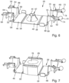
- Fig.6 shows the positioning component 26 of the fastening device 12 before assembly.
- the positioning component 26 is removed from a plastic injection molding tool.
- the positioning component 26 can be manufactured as a plastic injection molded part in large quantities, essentially without undercuts, and thus very cost-effectively.
- the positioning component 26 consists of a plastic that is elastically deformable, as will be explained below.
- the positioning component 26 has a base 40.
- a truncated cone-shaped elevation 42 is integrally connected to the base 40.
- the elevation 42 consists of four material strips 44 separated from one another by slots.
- the truncated cone-shaped elevation 42 has a concave outer contour.
- the elevation is hollow on the inside.
- the elevation 42 is intended to extend a little way into the through-opening of the sliding nut 28 and to position the sliding nut 28 relative to the base 40. Due to the concave and truncated cone-shaped design of the elevation 42, sliding nuts with through-openings of different sizes can be placed on the elevation.
- Sliding nuts with a large through-opening for example an M16 internal thread
- sliding nuts with a small through-opening for example an M6 internal thread.
- Sliding nuts for very large threaded rods are thicker than sliding nuts for small threaded rods or screws.
- an upper side of the sliding nuts can always be kept at the same height, which will be explained below.
- the positioning component 26 has a first side part 46 and a second side part 48.
- the two side parts 46, 48 are connected to opposite side edges of the base 40.
- a connection between the first side part 46 and the base 40 and between the second side part 48 and the base 40 is formed in each case by means of a film hinge 50.
- the positioning component 26 In the area of the film hinge 50, the positioning component 26 has a wall thickness that is significantly reduced compared to the base 40 and the side parts 46, 48. In the area of the film hinges 50, the positioning component 26 can therefore be bent without the film hinge 50 breaking.
- the first side part 46 Adjacent to the first side part 46 and opposite the base 40, the first side part 46 is connected to a first section 52 of an upper part of the positioning component 26. Symmetrically thereto, the second side part 48 is connected to a second section 54 of the upper part of the positioning component 26.
- the two sections 52, 54 each have a semicircular cylindrical section through which a screw or threaded rod can extend in the assembled state, with two semicircular cylindrical parts 56, 58 and 60, 62 respectively adjoining this semicircular cylindrical section.
- the two sections 52, 54 are not identical.
- the Fig.6 The first section 52 shown on the left has locking openings 64 which are arranged laterally of the semi-circular cylindrical section.
- Fig.6 right section 54 has locking projections 66 which are designed to match the locking openings 64 and in the assembled state, see Fig.9 , into which the locking openings 64 can snap.
- the Fig.6 The first section 52 shown on the left is also provided with positioning openings 68 into which positioning pins 70 on the Fig.6 the second section 54 shown on the right.
- the second section 54 shown on the right is also provided with two spherical fixing elements 72. These fixing elements 72 are molded onto the second parts 60, 62 by means of thin webs 74. The fixing elements 72 can thus be moved relative to the parts 60, 62.
- first side part 46 and the second side part 48 are each provided with V-shaped material strips 90.
- V-shaped material strips 90 form a braking device and are in the finished state of the fastening device 12, see Fig.10 , arranged on an upper side of the sliding nut 28.
- the fastening device 12 is inserted into the holding rail 14 and 90°, as shown in Fig.1 and Fig.4
- the material strips 90 press against a bottom side of the sections of the holding rail 14 which laterally limit the opening of the holding rail 40.
- This bottom side has, see Fig.4 , a corrugated formation.
- the tips of the V-shaped bent material strips 90 can then engage in depressions in this corrugation.
- the fastening device 12 is thereby secured in the retaining rail 14 in such a way that it cannot slip of its own accord, for example due to gravity. Nevertheless, the fastening device 12 can then be moved along the retaining rail 14 by applying light pressure.
- the V-shaped bent material strips 90 which form the braking device can then be moved along the corrugation and in the intended end position then engage again in a depression in the corrugation.
- the material strips 90 can, for example, also be curved or in the manner of a leaf spring with a projection which matches the corrugation.
- the sliding nut 28 is placed on the base 40 of the positioning component 26 so that the elevation 42, see Fig.6 , extends a little way into a through hole 76 of the sliding nut 28 with internal thread, and that the long side surfaces of the sliding nut 28 run parallel to the side edges of the base 40 or parallel to the film hinges 50.
- the sliding nut 28 can be positioned relative to the positioning component 26.
- the second side part 48 can also be bent upwards by 90° until the state of Fig.9 is reached.
- the locking projections 66 see Fig.6
- the positioning pins 70 have been inserted into the positioning openings 68.
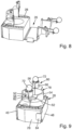
- the upper part 78 is now formed from the first section 52 and the second section 54. It can be seen that the upper part 78 forms a central through-opening through which the threaded rod 16 can be inserted and screwed into the through-opening 76 of the sliding nut 28.
- the upper part has a first hollow cylindrical projection 80 and a second hollow cylindrical projection 82.
- the first hollow cylindrical projection 80 is formed by the parts 60, 56 and the second hollow cylindrical projection is formed by the parts 62, 58.
- the spherical fixing elements 72 are now located above the hollow cylindrical projections 80, 82 and can, as will be explained, be pressed into the hollow cylindrical projections 80, 82.
- the sliding nut 28 is in Fig.9 sideways, i.e. to the right and to the left, by means of the first side part 46 and by means of the second side part 48. In a direction perpendicular to this, i.e. in Fig.9 from bottom left to top right, a displacement of the sliding nut 28 relative to the positioning component 26 is prevented by a retaining projection 84 on the second side part 48 or a Fig.9 not visible retaining projection on the first side part 46.
- the elevation 42 on the base of the positioning component 26 extends a little way into the through opening 76 of the sliding nut 28 and thus also prevents the sliding nut 28 from slipping relative to the positioning component 26.
- the spherical fixing elements 72 are now positioned based on the state of the Fig.10 downwards into the hollow cylindrical projections 80, 82. At the free end of the hollow cylindrical projections 80, 82, locking projections extending radially inwards are arranged. The fixing elements 72 are pressed into the hollow cylindrical projections 80, 82 until the fixing elements 72 are arranged below these locking elements. The fixing elements 72 cannot thereby come out of the hollow cylindrical projections 80, 82 again on their own. The two parts of the hollow cylindrical projection 80 and the hollow cylindrical projection 82 are thereby in Fig.10 to the right or left and thereby reliably secure the retaining disc 20 to the positioning component 26.
- the fastening device 12 After pressing the fixing elements 72 into the hollow cylindrical projections 80, 82, the fastening device 12 is completed and can be inserted into a holding rail 14.
- the Fig. 6 to 10 The described manufacture of the fastening device 12 can be carried out fully automatically. It was stated that the positioning component 26 in the state of Fig.6 can be removed from an injection molding tool. The fastening device 12 can therefore be manufactured in large quantities in an extremely cost-effective manner.
- Fig. 11 shows a sectional view of the fastening device 12 of the Fig.10 .
- the elevation 42 on the base 40 of the positioning component 26 extends a little way into the through-opening 76 of the sliding nut 28 and thereby positions the sliding nut 28 relative to the base 40.
- the sliding nut 28 is so thick that the underside rests on the base 40 and the top rests on the underside of the second section 54 of the upper part of the positioning component 26.
- Fig. 12 shows a fastening device 12A which, in contrast to the fastening device 12 of the Fig. 11 is provided with a sliding nut 28A which has a smaller through-opening 76A.
- the sliding nut 28A has a through-opening 76A with an M6 internal thread and the sliding nut 28 has a through-opening 76 with an M16 internal thread.
- the sliding nut 28A is also thinner than the sliding nut 28.
- the elevation 42 extends a little way into the through-opening 76A of the sliding nut 28A. Due to the smaller diameter of the through-opening 76A of the sliding nut 28A, the sliding nut 28A is held a little way above the base 40 of the positioning component 26.
- the sliding nut 28A cannot slide down as far along the concave outer contour of the elevation 42 as the sliding nut 28.
- the sliding nut 28A which is thinner than the sliding nut 28, is also held in such a way that its upper side rests against the first section 54 of the upper part of the positioning component 26.
Landscapes
- Engineering & Computer Science (AREA)
- General Engineering & Computer Science (AREA)
- Mechanical Engineering (AREA)
- Connection Of Plates (AREA)
- Clamps And Clips (AREA)
Claims (15)
- Dispositif de fixation (12) pour des rails de maintien (14) avec une section transversale au moins en partie en forme de C, avec un écrou coulissant (28, 28A), un disque de retenue (20) et un élément de positionnement (26), l'élément de positionnement (26) entourant au moins partiellement l'écrou coulissant (28, 28A) et l'élément de positionnement (26) maintenant le disque de retenue (20) à distance de l'écrou coulissant (28), l'élément de positionnement (26) présentant une base (40) qui est agencée à l'opposé d'une face inférieure de l'écrou coulissant (28), l'élément de positionnement (26) présentant une première partie latérale (46) et une deuxième partie latérale (48), la première partie latérale (46) et la deuxième partie latérale (48) étant reliées à la base (40) et reposant au moins partiellement sur des surfaces latérales opposées de l'écrou coulissant (28), l'élément de positionnement (26) présentant une partie supérieure (78) qui est agencée en regard d'une face supérieure de l'écrou coulissant (28), la partie supérieure (78) comprenant au moins une première section (52) et une deuxième section (54), la première section (52) étant reliée à la première partie latérale (46) et la deuxième section (54) étant reliée à la deuxième partie latérale (48), et la première section (52) et la deuxième section (54) étant reliées l'une à l'autre par des moyens d'encliquetage (66, 64).
- Dispositif de fixation selon la revendication 1, caractérisé en ce que la première partie latérale (46) et la base (40) sont reliées l'une à l'autre au moyen d'une première charnière-film (50) et en ce que la deuxième partie latérale (48) et la base (40) sont reliées l'une à l'autre au moyen d'une deuxième charnière-film (50).
- Dispositif de fixation selon la revendication 1 ou la revendication 2, caractérisé en ce que la base (40) est pourvue, sur sa face intérieure tournée vers l'écrou coulissant (28, 28A), d'une protubérance tronconique (42) qui s'engage partiellement dans une ouverture de passage (76, 76A) dans l'écrou coulissant (28, 28A), la protubérance (42) présentant en particulier un contour extérieur concave, la protubérance (42) étant en particulier pourvue d'une ouverture centrale.
- Dispositif de fixation selon la revendication 3, caractérisé en ce que la protubérance (42) est constituée de plusieurs bandes de matériau (44) qui sont chacune reliées à la base (40) et qui sont séparées les unes des autres au moins partiellement au moyen de fentes, les fentes s'étendant notamment jusqu'à l'extrémité supérieure effilée de la protubérance (42).
- Dispositif de fixation selon au moins l'une des revendications précédentes, caractérisé en ce que la partie supérieure (78) présente au moins une saillie cylindrique (80, 82) et en ce que le disque de retenue (20) présente une ouverture de passage adaptée à la saillie, la saillie (80, 82) s'étendant à travers l'ouverture de passage, ladite au moins une saillie (80, 82) étant notamment pourvue, dans la zone de son extrémité libre, d'une saillie d'encliquetage dépassant radialement vers l'extérieur, ladite au moins une saillie (80, 82) étant en particulier réalisée sous forme de cylindre creux, ladite au moins une saillie (80, 82) étant en particulier réalisée en deux parties, une première partie (56, 58) de la saillie (80, 82) étant reliée à la première section (52) de la partie supérieure (78) et une deuxième partie (60, 62) de la saillie (80, 82) étant reliée à la deuxième section (54) de la partie supérieure (78).
- Dispositif de fixation selon la revendication 5, caractérisé en ce que ladite au moins une saillie (80, 82) est de forme cylindrique creuse et en ce qu'un élément de fixation (72) est enfoncé dans l'extrémité ouverte de la saillie (80, 82), ladite au moins une saillie (80, 82) est pourvue, dans la zone de son extrémité libre, d'au moins une saillie d'encliquetage faisant saillie radialement vers l'intérieur, l'élément de fixation (72) étant notamment de forme sphérique, l'élément de fixation (72) étant notamment relié à la saillie (80, 82) au moyen d'une mince barrette ou d'une charnière-film.
- Agencement avec un dispositif de fixation (12) selon au moins l'une des revendications précédentes et un rail de retenue (14) avec une section transversale au moins partiellement en forme de C, l'écrou coulissant (28, 28A) étant agencé à l'intérieur de la section transversale en forme de C et le disque de retenue (20) reposant sur une ouverture de la section transversale en forme de C.
- Agencement selon la revendication 7, caractérisé en ce que l'élément de positionnement (26) comporte au moins un dispositif de freinage (90) et en ce que ledit au moins un dispositif de freinage (90) de l'élément de positionnement (26) est en appui contre le rail de maintien (14) de façon à empêcher le dispositif de fixation (12) de tomber et de glisser par rapport au rail de maintien (14).
- Agencement selon la revendication 8, caractérisé en ce que ledit au moins un dispositif de freinage est réalisé sous la forme d'une bande de matériau (90) s'étendant en forme de V, dont la pointe est en appui sur le rail de maintien (14).
- Agencement selon la revendication 7, 8 ou 9, caractérisé en ce qu'un composant avec un filetage extérieur, en particulier une vis ou une tige filetée (16), est vissé au moins partiellement dans une ouverture de passage (76, 76A) de l'écrou coulissant (28, 28A).
- Procédé de fabrication d'un dispositif de fixation (12) selon au moins l'une des revendications 1 à 6 cidessus, caractérisé par le fait de fabriquer l'élément de positionnement (26) sous la forme d'une pièce en matière plastique monobloc, le fait de positionner l'écrou coulissant (28, 28A) par rapport à l'élément de positionnement (26) de telle sorte que la protubérance (42) sur la base (40) de l'élément de positionnement (26) s'étend partiellement dans l'ouverture de passage (76, 76A) de l'écrou coulissant (28, 28A) ou repose sur une face supérieure de la protubérance (42) opposée à la base (40), le fait de plier les parties latérales (46, 48) de l'élément de positionnement (26) par rapport à la base (40), de sorte que les parties latérales (46, 48) reposent partiellement sur des surfaces latérales de l'écrou coulissant (28, 28A), le fait de relier les deux sections (52, 54) de la partie supérieure (78) de l'élément de positionnement (26) au moyen des éléments d'encliquetage (66, 64), de sorte que l'élément de positionnement (26) entoure l'écrou coulissant (28, 28A) au moins partiellement.
- Procédé selon la revendication 11, dans lequel la partie supérieure (78) présente au moins une saillie cylindrique (80, 82) et dans lequel le disque de retenue (20) présente une ouverture de passage adaptée à la saillie (80, 82), caractérisé par le fait de mettre en place le disque de retenue (20) sur l'élément de positionnement (26), de sorte que ladite au moins une saillie (80, 82) sur la partie supérieure (78) de l'élément de positionnement (26) s'étende à travers l'ouverture de passage dans le disque de retenue (20), ladite au moins une saillie (80, 82) étant en particulier de forme cylindrique creuse et un élément de fixation (72) étant prévu, caractérisé en particulier par le fait d'enfoncer l'élément de fixation (72) dans ladite au moins une saillie cylindrique creuse (80, 82).
- Procédé selon la revendication 11 ou la revendication 12, caractérisé par le fait de positionner entièrement automatiquement l'écrou coulissant (28, 28A) par rapport à l'élément de positionnement (26), le fait de plier entièrement automatiquement les parties latérales (46, 48) de l'élément de positionnement (26) par rapport à la base (40) et le fait d'assembler entièrement automatiquement les deux parties (52, 54) de la partie supérieure (78) de l'élément de positionnement (26) au moyen des éléments d'encliquetage (64, 66).
- Procédé selon la revendication 13, caractérisé par le fait de mettre en place entièrement automatiquement le disque de retenue (20) sur l'élément de positionnement (26) .
- Procédé selon la revendication 13 ou la revendication 14, caractérisé par le fait d'enfoncer entièrement automatiquement l'élément de fixation (72) dans la saillie cylindrique creuse (80, 82).
Applications Claiming Priority (1)
| Application Number | Priority Date | Filing Date | Title |
|---|---|---|---|
| DE102022203736.7A DE102022203736A1 (de) | 2022-04-13 | 2022-04-13 | Befestigungsvorrichtung, Anordnung mit einer Befestigungsvorrichtung und Verfahren zum Herstellen einer Befestigungsvorrichtung |
Publications (2)
| Publication Number | Publication Date |
|---|---|
| EP4261446A1 EP4261446A1 (fr) | 2023-10-18 |
| EP4261446B1 true EP4261446B1 (fr) | 2024-09-11 |
Family
ID=85980562
Family Applications (1)
| Application Number | Title | Priority Date | Filing Date |
|---|---|---|---|
| EP23167121.5A Active EP4261446B1 (fr) | 2022-04-13 | 2023-04-06 | Dispositif de fixation, ensemble comprenant un dispositif de fixation et procédé de fabrication d'un dispositif de fixation |
Country Status (4)
| Country | Link |
|---|---|
| EP (1) | EP4261446B1 (fr) |
| DE (1) | DE102022203736A1 (fr) |
| ES (1) | ES2992634T3 (fr) |
| FI (1) | FI4261446T3 (fr) |
Family Cites Families (8)
| Publication number | Priority date | Publication date | Assignee | Title |
|---|---|---|---|---|
| US4934886A (en) * | 1988-10-07 | 1990-06-19 | Gulton Industries, Inc. | Fastening assembly and method of fastening |
| DE4243185A1 (de) | 1992-12-19 | 1994-06-23 | Hilti Ag | Befestigungsvorrichtung |
| DE19912474C2 (de) | 1999-03-19 | 2001-05-10 | Wolfgang Pfitzmann | Befestigungsanordnung für die Anbringung eines Bauteils an einer C-förmigen Halteschiene |
| CA2890064C (fr) * | 2014-04-30 | 2022-08-16 | Cooper Technologies Company | Systeme de support a trapeze comprenant un raccord a blocage par pivotement |
| DE102014214853A1 (de) | 2014-07-29 | 2016-02-04 | Adolf Würth GmbH & Co. KG | Befestigungsanordnung für C-förmige Halteschienen und Bausatz |
| DE102015118314A1 (de) | 2014-12-09 | 2016-06-09 | Fischerwerke Gmbh & Co. Kg | Verfahren zum Befestigen eines Befestigungselements an einer Montageschiene sowie Befestigungselement |
| DE102017103770A1 (de) * | 2017-02-23 | 2018-08-23 | Secura Services Ag | Befestigungsvorrichtung und Befestigungsbaugruppe |
| NL2021935B1 (en) * | 2018-11-05 | 2020-05-15 | Walraven Holding Bv J Van | Channel fastener having flexible engagement of channel flange |
-
2022
- 2022-04-13 DE DE102022203736.7A patent/DE102022203736A1/de active Pending
-
2023
- 2023-04-06 ES ES23167121T patent/ES2992634T3/es active Active
- 2023-04-06 EP EP23167121.5A patent/EP4261446B1/fr active Active
- 2023-04-06 FI FIEP23167121.5T patent/FI4261446T3/fi active
Also Published As
| Publication number | Publication date |
|---|---|
| FI4261446T3 (fi) | 2024-12-07 |
| ES2992634T3 (en) | 2024-12-16 |
| EP4261446A1 (fr) | 2023-10-18 |
| DE102022203736A1 (de) | 2023-10-19 |
Similar Documents
| Publication | Publication Date | Title |
|---|---|---|
| DE19828059C2 (de) | Anschlußarmatur mit einem durch Schlitze in Haltezungen aufgeteilten Befestigungsvorsprung | |
| DE2724862C2 (de) | Koaxialsteckverbinder | |
| DE10349449B3 (de) | Befestigungselement zur Verbindung eines Bauteils mit einem Trägerbauteil | |
| DE19533727C2 (de) | Spiral-flexibles Halteelement | |
| DE2755674C2 (de) | Befestigungsvorrichtung | |
| DE19941499B4 (de) | Verbindungsstück zum Verbinden eines Wischblatts mit einem Wischerarm | |
| EP1297596B1 (fr) | Garniture de raccordement pourvue d'une bague elastique comme butee | |
| EP2003346A2 (fr) | Dispositif de fixation doté d'une égalisation de tolérance | |
| EP3707396B1 (fr) | Dispositif anti-détachement pour vis et unité de montage | |
| WO2017109099A1 (fr) | Douille d'écartement réglable | |
| WO2020200776A1 (fr) | Élément de réglage en plusieurs parties pour un agencement de compensation de tolérances | |
| DE102023205044A1 (de) | Vorrichtung zum Ausgleichen von Toleranzen zwischen zwei miteinander zu verbindenden Bauteilen | |
| EP3030795A1 (fr) | Élément de liaison élastique | |
| DE3038341A1 (de) | In eine wandoeffnung eines ersten bauteils einsetzbares und ueber eine rastnut mit diesem verrastbares aufnahmeteil | |
| EP4261446B1 (fr) | Dispositif de fixation, ensemble comprenant un dispositif de fixation et procédé de fabrication d'un dispositif de fixation | |
| DE102019206750B4 (de) | Vorrichtung zum Ausgleichen von Toleranzen zwischen einem ersten Bauteil und einem zweiten Bauteil | |
| DE2635970C3 (de) | Lockerungssicherung für eine auf einen Gewindebolzen aufgeschraubte Mutter | |
| DE102005037074A1 (de) | Scheinwerferverstellsystem | |
| DE2929461C2 (de) | Haltedübel | |
| DE2930833B2 (de) | Klemmuffe | |
| DE102020128076B4 (de) | Klemmelement für den Einbau einer Installationsdose sowie Installationsdose mit zumindest einem solchen Klemmelement | |
| DE19548364C2 (de) | Halterung für einen WC-Sitz | |
| DE29603389U1 (de) | Schnellverschluß | |
| EP3806695B1 (fr) | Tiroir et procédé de montage d'une paroi arrière sur un châssis latéral d'un tiroir | |
| DE19957977B4 (de) | Vorrichtung aus Abdeckelement und Gewindebolzen |
Legal Events
| Date | Code | Title | Description |
|---|---|---|---|
| PUAI | Public reference made under article 153(3) epc to a published international application that has entered the european phase |
Free format text: ORIGINAL CODE: 0009012 |
|
| STAA | Information on the status of an ep patent application or granted ep patent |
Free format text: STATUS: THE APPLICATION HAS BEEN PUBLISHED |
|
| AK | Designated contracting states |
Kind code of ref document: A1 Designated state(s): AL AT BE BG CH CY CZ DE DK EE ES FI FR GB GR HR HU IE IS IT LI LT LU LV MC ME MK MT NL NO PL PT RO RS SE SI SK SM TR |
|
| STAA | Information on the status of an ep patent application or granted ep patent |
Free format text: STATUS: REQUEST FOR EXAMINATION WAS MADE |
|
| 17P | Request for examination filed |
Effective date: 20231205 |
|
| RBV | Designated contracting states (corrected) |
Designated state(s): AL AT BE BG CH CY CZ DE DK EE ES FI FR GB GR HR HU IE IS IT LI LT LU LV MC ME MK MT NL NO PL PT RO RS SE SI SK SM TR |
|
| GRAP | Despatch of communication of intention to grant a patent |
Free format text: ORIGINAL CODE: EPIDOSNIGR1 |
|
| STAA | Information on the status of an ep patent application or granted ep patent |
Free format text: STATUS: GRANT OF PATENT IS INTENDED |
|
| INTG | Intention to grant announced |
Effective date: 20240411 |
|
| GRAS | Grant fee paid |
Free format text: ORIGINAL CODE: EPIDOSNIGR3 |
|
| RAP1 | Party data changed (applicant data changed or rights of an application transferred) |
Owner name: WUERTH INTERNATIONAL AG Owner name: ADOLF WUERTH GMBH & CO. KG |
|
| GRAA | (expected) grant |
Free format text: ORIGINAL CODE: 0009210 |
|
| STAA | Information on the status of an ep patent application or granted ep patent |
Free format text: STATUS: THE PATENT HAS BEEN GRANTED |
|
| AK | Designated contracting states |
Kind code of ref document: B1 Designated state(s): AL AT BE BG CH CY CZ DE DK EE ES FI FR GB GR HR HU IE IS IT LI LT LU LV MC ME MK MT NL NO PL PT RO RS SE SI SK SM TR |
|
| REG | Reference to a national code |
Ref country code: GB Ref legal event code: FG4D Free format text: NOT ENGLISH |
|
| REG | Reference to a national code |
Ref country code: CH Ref legal event code: EP |
|
| REG | Reference to a national code |
Ref country code: DE Ref legal event code: R096 Ref document number: 502023000161 Country of ref document: DE |
|
| REG | Reference to a national code |
Ref country code: IE Ref legal event code: FG4D Free format text: LANGUAGE OF EP DOCUMENT: GERMAN |
|
| P01 | Opt-out of the competence of the unified patent court (upc) registered |
Free format text: CASE NUMBER: APP_54157/2024 Effective date: 20241001 |
|
| REG | Reference to a national code |
Ref country code: FI Ref legal event code: FGE |
|
| REG | Reference to a national code |
Ref country code: ES Ref legal event code: FG2A Ref document number: 2992634 Country of ref document: ES Kind code of ref document: T3 Effective date: 20241216 |
|
| REG | Reference to a national code |
Ref country code: LT Ref legal event code: MG9D |
|
| PG25 | Lapsed in a contracting state [announced via postgrant information from national office to epo] |
Ref country code: NO Free format text: LAPSE BECAUSE OF FAILURE TO SUBMIT A TRANSLATION OF THE DESCRIPTION OR TO PAY THE FEE WITHIN THE PRESCRIBED TIME-LIMIT Effective date: 20241211 |
|
| REG | Reference to a national code |
Ref country code: NL Ref legal event code: MP Effective date: 20240911 |
|
| PG25 | Lapsed in a contracting state [announced via postgrant information from national office to epo] |
Ref country code: GR Free format text: LAPSE BECAUSE OF FAILURE TO SUBMIT A TRANSLATION OF THE DESCRIPTION OR TO PAY THE FEE WITHIN THE PRESCRIBED TIME-LIMIT Effective date: 20241212 |
|
| PG25 | Lapsed in a contracting state [announced via postgrant information from national office to epo] |
Ref country code: BG Free format text: LAPSE BECAUSE OF FAILURE TO SUBMIT A TRANSLATION OF THE DESCRIPTION OR TO PAY THE FEE WITHIN THE PRESCRIBED TIME-LIMIT Effective date: 20240911 |
|
| PG25 | Lapsed in a contracting state [announced via postgrant information from national office to epo] |
Ref country code: LV Free format text: LAPSE BECAUSE OF FAILURE TO SUBMIT A TRANSLATION OF THE DESCRIPTION OR TO PAY THE FEE WITHIN THE PRESCRIBED TIME-LIMIT Effective date: 20240911 |
|
| PG25 | Lapsed in a contracting state [announced via postgrant information from national office to epo] |
Ref country code: HR Free format text: LAPSE BECAUSE OF FAILURE TO SUBMIT A TRANSLATION OF THE DESCRIPTION OR TO PAY THE FEE WITHIN THE PRESCRIBED TIME-LIMIT Effective date: 20240911 |
|
| PG25 | Lapsed in a contracting state [announced via postgrant information from national office to epo] |
Ref country code: RS Free format text: LAPSE BECAUSE OF FAILURE TO SUBMIT A TRANSLATION OF THE DESCRIPTION OR TO PAY THE FEE WITHIN THE PRESCRIBED TIME-LIMIT Effective date: 20241211 |
|
| PG25 | Lapsed in a contracting state [announced via postgrant information from national office to epo] |
Ref country code: RS Free format text: LAPSE BECAUSE OF FAILURE TO SUBMIT A TRANSLATION OF THE DESCRIPTION OR TO PAY THE FEE WITHIN THE PRESCRIBED TIME-LIMIT Effective date: 20241211 Ref country code: NO Free format text: LAPSE BECAUSE OF FAILURE TO SUBMIT A TRANSLATION OF THE DESCRIPTION OR TO PAY THE FEE WITHIN THE PRESCRIBED TIME-LIMIT Effective date: 20241211 Ref country code: LV Free format text: LAPSE BECAUSE OF FAILURE TO SUBMIT A TRANSLATION OF THE DESCRIPTION OR TO PAY THE FEE WITHIN THE PRESCRIBED TIME-LIMIT Effective date: 20240911 Ref country code: HR Free format text: LAPSE BECAUSE OF FAILURE TO SUBMIT A TRANSLATION OF THE DESCRIPTION OR TO PAY THE FEE WITHIN THE PRESCRIBED TIME-LIMIT Effective date: 20240911 Ref country code: GR Free format text: LAPSE BECAUSE OF FAILURE TO SUBMIT A TRANSLATION OF THE DESCRIPTION OR TO PAY THE FEE WITHIN THE PRESCRIBED TIME-LIMIT Effective date: 20241212 Ref country code: BG Free format text: LAPSE BECAUSE OF FAILURE TO SUBMIT A TRANSLATION OF THE DESCRIPTION OR TO PAY THE FEE WITHIN THE PRESCRIBED TIME-LIMIT Effective date: 20240911 |
|
| PG25 | Lapsed in a contracting state [announced via postgrant information from national office to epo] |
Ref country code: NL Free format text: LAPSE BECAUSE OF FAILURE TO SUBMIT A TRANSLATION OF THE DESCRIPTION OR TO PAY THE FEE WITHIN THE PRESCRIBED TIME-LIMIT Effective date: 20240911 |
|
| PG25 | Lapsed in a contracting state [announced via postgrant information from national office to epo] |
Ref country code: IS Free format text: LAPSE BECAUSE OF FAILURE TO SUBMIT A TRANSLATION OF THE DESCRIPTION OR TO PAY THE FEE WITHIN THE PRESCRIBED TIME-LIMIT Effective date: 20250111 Ref country code: PT Free format text: LAPSE BECAUSE OF FAILURE TO SUBMIT A TRANSLATION OF THE DESCRIPTION OR TO PAY THE FEE WITHIN THE PRESCRIBED TIME-LIMIT Effective date: 20250113 |
|
| PG25 | Lapsed in a contracting state [announced via postgrant information from national office to epo] |
Ref country code: SM Free format text: LAPSE BECAUSE OF FAILURE TO SUBMIT A TRANSLATION OF THE DESCRIPTION OR TO PAY THE FEE WITHIN THE PRESCRIBED TIME-LIMIT Effective date: 20240911 Ref country code: RO Free format text: LAPSE BECAUSE OF FAILURE TO SUBMIT A TRANSLATION OF THE DESCRIPTION OR TO PAY THE FEE WITHIN THE PRESCRIBED TIME-LIMIT Effective date: 20240911 |
|
| PG25 | Lapsed in a contracting state [announced via postgrant information from national office to epo] |
Ref country code: EE Free format text: LAPSE BECAUSE OF FAILURE TO SUBMIT A TRANSLATION OF THE DESCRIPTION OR TO PAY THE FEE WITHIN THE PRESCRIBED TIME-LIMIT Effective date: 20240911 |
|
| PG25 | Lapsed in a contracting state [announced via postgrant information from national office to epo] |
Ref country code: CZ Free format text: LAPSE BECAUSE OF FAILURE TO SUBMIT A TRANSLATION OF THE DESCRIPTION OR TO PAY THE FEE WITHIN THE PRESCRIBED TIME-LIMIT Effective date: 20240911 Ref country code: PL Free format text: LAPSE BECAUSE OF FAILURE TO SUBMIT A TRANSLATION OF THE DESCRIPTION OR TO PAY THE FEE WITHIN THE PRESCRIBED TIME-LIMIT Effective date: 20240911 |
|
| PG25 | Lapsed in a contracting state [announced via postgrant information from national office to epo] |
Ref country code: SK Free format text: LAPSE BECAUSE OF FAILURE TO SUBMIT A TRANSLATION OF THE DESCRIPTION OR TO PAY THE FEE WITHIN THE PRESCRIBED TIME-LIMIT Effective date: 20240911 |
|
| REG | Reference to a national code |
Ref country code: DE Ref legal event code: R097 Ref document number: 502023000161 Country of ref document: DE |
|
| PGFP | Annual fee paid to national office [announced via postgrant information from national office to epo] |
Ref country code: FI Payment date: 20250424 Year of fee payment: 3 |
|
| PGFP | Annual fee paid to national office [announced via postgrant information from national office to epo] |
Ref country code: DE Payment date: 20250422 Year of fee payment: 3 |
|
| PG25 | Lapsed in a contracting state [announced via postgrant information from national office to epo] |
Ref country code: DK Free format text: LAPSE BECAUSE OF FAILURE TO SUBMIT A TRANSLATION OF THE DESCRIPTION OR TO PAY THE FEE WITHIN THE PRESCRIBED TIME-LIMIT Effective date: 20240911 |
|
| PGFP | Annual fee paid to national office [announced via postgrant information from national office to epo] |
Ref country code: ES Payment date: 20250530 Year of fee payment: 3 |
|
| PGFP | Annual fee paid to national office [announced via postgrant information from national office to epo] |
Ref country code: IT Payment date: 20250430 Year of fee payment: 3 |
|
| PGFP | Annual fee paid to national office [announced via postgrant information from national office to epo] |
Ref country code: FR Payment date: 20250425 Year of fee payment: 3 |
|
| PLBE | No opposition filed within time limit |
Free format text: ORIGINAL CODE: 0009261 |
|
| STAA | Information on the status of an ep patent application or granted ep patent |
Free format text: STATUS: NO OPPOSITION FILED WITHIN TIME LIMIT |
|
| PGFP | Annual fee paid to national office [announced via postgrant information from national office to epo] |
Ref country code: AT Payment date: 20250721 Year of fee payment: 3 |
|
| 26N | No opposition filed |
Effective date: 20250612 |
|
| PG25 | Lapsed in a contracting state [announced via postgrant information from national office to epo] |
Ref country code: SE Free format text: LAPSE BECAUSE OF FAILURE TO SUBMIT A TRANSLATION OF THE DESCRIPTION OR TO PAY THE FEE WITHIN THE PRESCRIBED TIME-LIMIT Effective date: 20240911 |
|
| PG25 | Lapsed in a contracting state [announced via postgrant information from national office to epo] |
Ref country code: LU Free format text: LAPSE BECAUSE OF NON-PAYMENT OF DUE FEES Effective date: 20250406 |
|
| PG25 | Lapsed in a contracting state [announced via postgrant information from national office to epo] |
Ref country code: MC Free format text: LAPSE BECAUSE OF FAILURE TO SUBMIT A TRANSLATION OF THE DESCRIPTION OR TO PAY THE FEE WITHIN THE PRESCRIBED TIME-LIMIT Effective date: 20240911 |
|
| REG | Reference to a national code |
Ref country code: BE Ref legal event code: MM Effective date: 20250430 |
|
| PG25 | Lapsed in a contracting state [announced via postgrant information from national office to epo] |
Ref country code: BE Free format text: LAPSE BECAUSE OF NON-PAYMENT OF DUE FEES Effective date: 20250430 |
|
| PG25 | Lapsed in a contracting state [announced via postgrant information from national office to epo] |
Ref country code: IE Free format text: LAPSE BECAUSE OF NON-PAYMENT OF DUE FEES Effective date: 20250406 |