EP2210059B1 - Verfahren zum integrieren eines vibrationssignals aus signaldifferenzen und entsprechendes verfahren zum korrigieren eines durch einen bildsensor erfassten signals - Google Patents
Verfahren zum integrieren eines vibrationssignals aus signaldifferenzen und entsprechendes verfahren zum korrigieren eines durch einen bildsensor erfassten signals Download PDFInfo
- Publication number
- EP2210059B1 EP2210059B1 EP08839826.8A EP08839826A EP2210059B1 EP 2210059 B1 EP2210059 B1 EP 2210059B1 EP 08839826 A EP08839826 A EP 08839826A EP 2210059 B1 EP2210059 B1 EP 2210059B1
- Authority
- EP
- European Patent Office
- Prior art keywords
- signal
- instant
- calculator
- integrator
- linear combination
- Prior art date
- Legal status (The legal status is an assumption and is not a legal conclusion. Google has not performed a legal analysis and makes no representation as to the accuracy of the status listed.)
- Active
Links
Images

Classifications
-
- G—PHYSICS
- G01—MEASURING; TESTING
- G01C—MEASURING DISTANCES, LEVELS OR BEARINGS; SURVEYING; NAVIGATION; GYROSCOPIC INSTRUMENTS; PHOTOGRAMMETRY OR VIDEOGRAMMETRY
- G01C11/00—Photogrammetry or videogrammetry, e.g. stereogrammetry; Photographic surveying
- G01C11/04—Interpretation of pictures
- G01C11/06—Interpretation of pictures by comparison of two or more pictures of the same area
-
- B—PERFORMING OPERATIONS; TRANSPORTING
- B64—AIRCRAFT; AVIATION; COSMONAUTICS
- B64G—COSMONAUTICS; VEHICLES OR EQUIPMENT THEREFOR
- B64G1/00—Cosmonautic vehicles
- B64G1/10—Artificial satellites; Systems of such satellites; Interplanetary vehicles
- B64G1/1021—Earth observation satellites
-
- H—ELECTRICITY
- H04—ELECTRIC COMMUNICATION TECHNIQUE
- H04N—PICTORIAL COMMUNICATION, e.g. TELEVISION
- H04N23/00—Cameras or camera modules comprising electronic image sensors; Control thereof
- H04N23/60—Control of cameras or camera modules
- H04N23/68—Control of cameras or camera modules for stable pick-up of the scene, e.g. compensating for camera body vibrations
Definitions
- the invention relates to an integration method for obtaining a harmonic or quasi-harmonic vibratory signal originating from an image sensor from at least one measurement representative of a differential of said vibratory signal, said vibratory signal being composed of n known stationary or quasi-stationary pulsations ⁇ i .
- the invention also relates to a corresponding method for correcting a signal acquired by an image sensor.
- a conventional solution for integrating a stationary or quasi-stationary harmonic or quasi-harmonic signal consists in passing through frequency space (for example by Fourier transform) and in applying a filter which depends on the integration step. This classic solution is described for example in FR 2 899 344 .
- FR 2 899 344 further discloses a solution for integrating very low frequency noise, using polynomial signal modeling, and using all available signal time samples after observation of all the signal, to model the coefficients of the temporal polynomial, by least squares.
- the invention proposes to overcome at least one of these drawbacks. It is defined in the claims.
- the invention has many advantages.
- the invention mainly makes it possible to integrate a vibratory signal in temporal space, on condition that several measurements of signal differentials are available.
- the approximate solution is obtained by least squares approximation.
- the invention does not require any preprocessing of the signal (of the Fourier transform type).
- the invention allows a point-by-point restitution (that is to say at each instant) of the sought signal. It is not necessary to observe the whole signal: the integration is local, in other words it takes place in real time.
- Linear coefficients are constants that are independent of time and shooting.
- the interval over which the differential measurements are taken is very narrow: in general, it suffices to have one to six very close consecutive samples (example: 1ms), in order to be able to carry out an integration at an instant t included in the aforementioned interval .
- the invention allows integration of a signal composed of harmonics, in particular high frequencies and very high frequencies.
- the invention does not have cut-off frequencies if independent differentials are combined. Iteration is possible in some cases to improve the accuracy of the results, but is not necessary.
- Signal sampling may be spotty or spotty.
- the invention is applicable to the correction of the vibratory part of a signal acquired by an image sensor mounted on a carrier.
- Non-limiting examples of this correction are in particular the improvement of the quality images acquired by microscopes and cameras at very high magnification, stabilization of the line of sight of an aircraft (for example a helicopter in flight and observing an environment) or the restitution of residual satellite attitudes (roll, pitch or yaw) from measurements of attitude differences between the various images successively taken by a sensor on board the satellite.
- the invention makes it possible in particular to automatically determine the high frequency attitude profiles making it possible to correct the geometry of the images.
- the figures 1 and 2 very schematically show two non-limiting examples of a carrier 10 on which an image sensor 4 is mounted.
- the invention is advantageously applied to a carrier 10 of the artificial satellite type moving relative to a scene 6 (example of the figure 1 ). It is desired to emphasize that the invention applies to other types of carriers 10, in particular quasi-static with respect to the scene 6 to be observed, for example of the microscope type (example of the figure 2 ).
- the bars and the matrix include pixels 40 making it possible to form at least one image of the scene 6 to be observed.
- the images acquired by an Earth observation satellite exhibit geometric deformations linked to the orbital movement of the satellite, to its attitude, to the internal geometry of the instrument, and to the relief of the observed scene.
- the auxiliary data and the calibration of the model are used to calculate at each instant the orientation of the sighting frame, and therefore, for each pixel 40, the intersection of its sighting direction with the Earth.
- the auxiliary data can account for disturbances up to a cutoff frequency, for example of the order of 8 to 16 Hz.
- the sensor 4 includes strips of detectors (in the case of figure 1 ) who see the landscape at different times, the variations in the attitude of the satellite are observable to a certain extent, since they induce position shifts in the same detail of the landscape between the different images produced by the different bars.
- the figure 1 shows that the bars B0 and B2 of satellite 10, for example, acquire an image of scene 6 at an instant t - ⁇ , then an image of scene 6 at an instant t, the satellite 10 having moved between the instants t - ⁇ and t .
- Such a phenomenon of deformation of the image of the scene by the vibrations 7 of the carrier 10 is also possible in the case of a telescope acquiring a scene 6 at different times. Indeed, when such images are acquired with a high optical magnification, for example by a microscope or a camera, the vibrations of the camera or of the whole [object + camera] , lead to the same technical problem as that of the satellite images mentioned above.
- an integration method for obtaining a harmonic or quasi-harmonic vibratory signal originating from an image sensor from at least one measurement representative of a differential of said vibratory signal.
- the vibratory signal is composed of n known stationary or quasi-stationary pulsations ⁇ i .
- the ⁇ i generally depend on the vibratory properties of the carrier 10. It is for this reason that they are known.
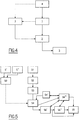
- a device for implementing a method according to the invention comprises, as shown in figure 4 , a module 1 for processing the images coming from the sensor 4, an integrator 2 for integrating the signal coming from the module 1, and a computer 3 making it possible to calculate the coefficients which will be used by the integrator 2.
- the processing module 1, the integrator 2, and the computer 3 can be on board or on the ground. In the case of a microscope, module 1, integrator 2, and calculator 3 can be remote.
- the method mainly comprises a step S4 according to which the integrator 2 integrates the vibratory signal x ⁇ ( t ) by performing a linear combination of m measurements ⁇ x ⁇ ( t k , ⁇ j ) for each instant t k from the module 1.
- Each coefficient w jk of the linear combination is a function of the known pulsations ⁇ i, of the known shifts ⁇ j , and of the position of the measurement ⁇ x ⁇ ( t k , ⁇ j ) in the time interval I. They are calculated by the computer 3 during a calibration step S0.
- the time shifts ⁇ j are generally a function of the geometric properties of the sensor 4 and / or of a displacement of the carrier 10. It is for this reason that they are known.
- the differential ⁇ ⁇ ( t , ⁇ j ) contains information for all the non-harmonic frequencies of 1 / ⁇ j .
- the vector ⁇ ( ⁇ , ⁇ j ) has at least one non-zero coordinate.
- Signals y ⁇ t and ⁇ y ⁇ t ⁇ j are both expressed as a function of the vector v ( a , ⁇ , ⁇ , t).
- a harmonic signal x ⁇ t composed of n stationary pulsations can be expressed as a linear combination of 2 ⁇ n diferentials ⁇ ⁇ x ⁇ t ⁇ j from module 1.
- the coefficients w j depend on the pulsations ⁇ i and on the offsets ⁇ j . They are not time dependent (they are stationary). To be able to calculate x ⁇ t depending on the measurements ⁇ x ⁇ t ⁇ j , it is therefore necessary to know the frequencies present on the signal, to obtain the pulsations ⁇ i and the shifts ⁇ j .
- the differentials ⁇ x ⁇ t ⁇ j will be measured discreetly by module 1, if possible at regular intervals dt, and will be noisy.
- the detectable frequencies are theoretically less than 1 / (2dt) (Nyquist frequency), and their amplitude must be greater than the signal / noise ratio.
- Module 1 therefore provides the measurements ⁇ x ⁇ ( t k , ⁇ j ) so that the time shifts ⁇ j are such that the frequencies f i can be considered as quasi-stationary between t- ⁇ j and t, despite the drift ⁇ i (t).
- the computer 3 removes, in the linear combination during step S0, the terms corresponding to the estimated differentials ⁇ y ⁇ t k ⁇ j (and therefore the measurements ⁇ x ⁇ ( t k , ⁇ j )) whose amplitude is less than a determined threshold, and can therefore be considered negligible.
- This threshold is relative to the average of the amplitudes of the coefficients w ik. And guided by the difference between the global variance and the variance restored by the non-eliminated variables reduced to noise.
- a new calibration step S0 is performed to redetermine the coefficients of the linear combination.
- the integrator 2 performs the integration step S4 by using the linear coefficients retained.
- the solution thus regularized is more stable, because a regularized statistical solution will present fewer cut-off frequencies.
- x ⁇ t w H ⁇ ⁇ x ⁇ t - p ⁇ dt , ⁇ 1 ⁇ ⁇ x ⁇ t - p ⁇ dt , ⁇ m ⁇ ⁇ x ⁇ t ⁇ 1 ⁇ ⁇ x ⁇ t ⁇ m ⁇ ⁇ x ⁇ t + p ⁇ dt , ⁇ 1 ⁇ ⁇ x ⁇ t + p ⁇ dt , ⁇ 1 ⁇ ⁇ x ⁇ t + p ⁇ dt , ⁇ m + ⁇ w
- ⁇ w represents the difference between the approximate model and reality.
- the integrator 2 then integrates the signal at the instant t.
- a method according to the invention is applied to signals of zero mean.
- the integrator 2 preferably performs, during a step S4 ′, a centering of the vibratory signal before applying the coefficients w jk during the step S5, to obtain a signal of zero mean.
- the integrator 2 therefore preferably performs, during a step S6 ′, a filtering on the signal x ⁇ ( t ) in order to be free from the restitution noise and to eliminate frequencies that are not very observable.
- the ws are calibrated on a priori knowledge of the frequencies (average, noise, drift).
- the real frequencies of the signal can therefore be slightly different from the simulation for the calculation of w.
- the integrator 2 therefore advantageously performs, during a step S6 ", a global rephasing of the vibratory signal x ⁇ ( t ) by minimization of the mean square error between the measurements ⁇ x ⁇ ( t k , ⁇ y ) coming from the module 1 and the estimated differentials ⁇ y ⁇ t k ⁇ j by calculator 3.
- the iterations (S6 "') include the centering (S4'), the possible filtering (S6 ') and the rephasing (S6").
- a method according to the invention searches for a harmonic signal with several pulsations which may be noisy (frequencies and amplitudes), from measurements noisy shift too.
- a corrector 5 (visible at figure 4 ) can then correct (during a step S5) the signal acquired by the image sensor 4 by removing the vibratory part thus integrated.
- a particular treatment will treat the beginnings of the shooting and the correlation holes.
- the correction attitude profile will then be frequency filtered to avoid correcting frequencies outside the desired restitution range.
- tellite images applies to more conventional images such as those taken, for example, by a camera or even a microscope.
- a method according to the invention is advantageously implemented for certain satellites to devibrate the images, in order to secure the image quality performance in flight, in the event that the attitude of the satellite is disturbed by high frequency phenomena.
Landscapes
- Engineering & Computer Science (AREA)
- Remote Sensing (AREA)
- Physics & Mathematics (AREA)
- General Physics & Mathematics (AREA)
- Multimedia (AREA)
- Astronomy & Astrophysics (AREA)
- Signal Processing (AREA)
- Radar, Positioning & Navigation (AREA)
- Aviation & Aerospace Engineering (AREA)
- Measurement Of Mechanical Vibrations Or Ultrasonic Waves (AREA)
Claims (20)
- Integrationsverfahren zum Erhalten eines harmonischen Vibrationssignals, das aus einem Bildsensor (4) stammt, der auf einem Träger (10) montiert ist, aus mindestens einer repräsentativen Messung einer Differenz des Vibrationssignals, wobei sich das Vibrationssignal aus n bekannten stationären oder quasi-stationären Pulsationen ω i zusammensetzt,
wobei das Verfahren dadurch gekennzeichnet ist, dass es die Schritte beinhaltet, wonach:- ein Integrator (2) das Vibrationssignal x̂(t) integriert (S4), indem er eine Linearkombination von m Messungen Δx̂(t k, τj ) für jeden Moment tk durchführt, die aus einem Verarbeitungsmodul (1) der Bilder stammen, die aus dem Sensor (4) stammen, wobei die Linearkombination in der folgenden Form ist: wobei m ≤ 2n ist;tk einem Zeitintervall I angehört, das t einschließt, wobei das Intervall I in der folgenden Form ist
 wobei dt der Stichprobenahme-Schritt der Messungen Δx̂(tk ,τj ) durch das Modul (1) ist;die Intervalle [0; p'] und [0; p] in den natürlichen ganzen Zahlen eingeschlossen sind.die m Messungen zwischen dem Moment tk und Momenten tk-τj erfolgen, die um bekannte Zeitverschiebungen τj beabstandet sind,jeder Koeffizient wjk der Linearkombination eine Funktion der bekannten Pulsationen ωi, der bekannten Verschiebungen τj und der Position der Messung Δx̂(t k, τj) in dem Zeitintervall I ist, und- das Signal als harmonisch stationär angesehen wird, wobei ein Rechner (3) somit das zu integrierende Signal in der folgenden Form modelliert:
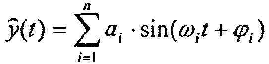
wobei das Verfahren weiter einen Schritt beinhaltet, wonach der Rechner (3) Folgendes ansetzt:

 wobei: (B(ω,τ)-1) H die transponierte Matrix der Matrix B(ω,τ)-1 istB(ω,τ)-1 der Kehrwert der Matrix B(ω,τ) ist,B(ω,τ) eine quadratische Matrix m x m der folgenden Form ist:
 α eine Säulenmatrix mit m Zeilen ist, die einen Koeffizienten 1 aufweist
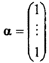
- Integrationsverfahren zum Erhalten eines quasi-harmonischen Vibrationssignals, das aus einem Bildsensor (4) stammt, der auf einem Träger (10) montiert ist, aus mindestens einer repräsentativen Messung einer Differenz des Vibrationssignals, wobei sich das Vibrationssignal aus n bekannten stationären oder quasi-stationären Pulsationen ω i zusammensetzt,
wobei das Verfahren dadurch gekennzeichnet ist, dass es die Schritte beinhaltet, wonach:- ein Integrator (2) das Vibrationssignal x̂(t) integriert (S4), indem er eine Linearkombination von m Messungen Δx̂(tk ,τj ) für jeden Moment tk durchführt, die aus einem Verarbeitungsmodul (1) der Bilder stammen, die aus dem Sensor (4) stammen, wobei die Linearkombination in der folgenden Form ist: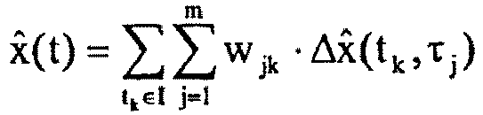 wobei m ≤ 2n ist;tk einem Zeitintervall I angehört, das t einschließt, wobei das Intervall I in der folgenden Form ist
 wobei dt der Stichprobenahme-Schritt der Messungen Δx̂(tk ,τj ) durch das Modul (1) ist;die Intervalle [0; p'] und [0; p] in den natürlichen ganzen Zahlen eingeschlossen sind;die m Messungen zwischen dem Moment tk und den Momenten tk-τj erfolgen, die um bekannte Zeitverschiebungen τj beabstandet sind,jeder Koeffizient wjk der Linearkombination eine Funktion der bekannten Pulsationen ωi, der bekannten Verschiebungen τj und der Position der Messung Δx̂(tk ,τj ) in dem Zeitintervall I ist, und- das Signal als quasi-harmonisch und quasi-stationär angesehen wird, wobei ein Rechner (3) somit das zu integrierende Signal in der folgenden Form modelliert:
 wobei (a i +εa ) die Amplitude der Pulsation ω i repräsentiert,ϕi ihre Phase repräsentiert, undwobei Rechner (3) Folgendes ansetzt:
 wobei ε a und ε f zufällige Variable einer Gauß-Verteilung mit Null-Mittelwert mit jeweiligen typischen Abweichungen σ f und σ h ist, die in jedem Moment tk gezogen werden,vi(tk) eine zeitliche Abdrift jeder Frequenz fi repräsentiert;wobei der Rechner (3) den Vektor w berechnet (S0), der die Koeffizienten wjk der Linearkombination durch das Verfahren der kleinsten Quadrate durch die folgende Formel zusammenfasst:
 wobei RΔy -1der Kehrwert der Matrix R Δy ist,RΔy die Varianz-Kovarianz-Matrix der Matrix Δŷ(t k,τ) ist, die die geschätzten Differenzen m x (p+p'+1) zusammenfasst, wobei jede in der folgenden Form ist:
 rΔ y.dy der gekreuzte Korrelationsvektor zwischen
- Verfahren nach Anspruch 2, wobei der Rechner (3) RΔ y und rΔy.dy dank der folgenden Formeln berechnet:


- Verfahren nach einem der Ansprüche 2 oder 3, wobei- der Rechner (3) in der Linearkombination die Termini löscht, die den geschätzten Differenzen
 - der Rechner (3) die Koeffizienten der Linearkombination neu berechnet;- der Integrator (2) das Signal integriert, indem er die gehaltenen Koeffizienten verwendet.
 - Verfahren nach einem der Ansprüche 2 bis 4, wobei der Rechner (3) das Messrauschen simuliert, indem er Folgendes ansetzt:

- Verfahren nach einem der Ansprüche 2 bis 5, wobei der Rechner (3) Folgendes ansetzt:

- Verfahren nach einem der Ansprüche 2 bis 6, wobei der Rechner (3) zur Durchführung (S0) der Berechnungen der Koeffizienten wjk verfügbare Messungen mit den Verschiebungen durchführt, die zu den Zeiten nahe der Zeit t im Intervall / erhalten werden, mit
wobei der Integrator (2) die Integration im Intervall I durchführt. - Verfahren nach Anspruch 7, wobei der Rechner p'=p ansetzt.
- Verfahren nach einem der Ansprüche 5 bis 8, wobei das Modul (1) die Messungen Δx̂( tk ,τj ) bereitstellt, sodass die kleinste Verschiebung τj lautet:
- Verfahren nach einem der Ansprüche 5 bis 9, wobei das Modul (1) die Messungen Δx̂(tk ,τj ) bereitstellt, sodass die Zeitverschiebungen τj derart sind, dass die Frequenzen fi zwischen t-τj und t als quasi-stationär angesehen werden können.
- Verfahren nach einem der Ansprüche 2 bis 10, wobei der Integrator (2) vor dem Anwenden (S4) der Koeffizienten wjk eine Zentrierung des Vibrationssignals durchführt (S4'), um ein Signal mit Null-Mittelwert zu erhalten.
- Verfahren nach einem der Ansprüche 2 bis 11, wobei der Integrator (2) eine Filterung am Signal x̂(t) durchführt (S6'), um wenig beobachtbare Frequenzen zu eliminieren.
- Verfahren nach einem der Ansprüche 2 bis 12, wobei der Integrator (2) einen globalen Phasenausgleich des Vibrationssignals x̂(t) durch Minimieren des mittleren quadratischen Fehlers zwischen den Messungen Δx̂(tk ,τj ) und den geschätzten Differenzen x̂(t)-x̂(t-τj ) durchführt (S6").
- Verfahren nach einem der Ansprüche 5 bis 13, wobei der Integrator (2) eine Iteration der folgenden Form durchführt (S6"'):1. Δx̂(tk ,τj ) =ursprüngliche Messung2. x̂(tk )=w H .(Δx̂(tk ,τ))
Danach, sofern Δx̂(t k, τj )>3σΔ, ∀j∈[1,m] ist3. Δx̂(tk ,τj )⇐Δx̂(tk ,τj )-(x̂(tk )-x̂(tk -τj ))4. x̂(t k )⇐x̂(tk )+w H ·(Δx̂(tk ,τ)) - Verfahren zum Korrigieren, in einem Moment t, des Vibrationsteils eines Signals, das durch einen Bildsensor (4) erfasst wird, der auf einem Träger (10) montiert ist,
wobei der Sensor (4) eine Vielzahl von Pixeln (40) beinhaltet,
wobei das Vibrationsteil in Form eines harmonischen oder quasi-harmonischen Vibrationssignals, das sich aus n bekannten stationären oder quasi-stationären Pulsationen ω i zusammensetzt, ist,
wobei die ωi von den Vibrationseigenschaften des Trägers (10) abhängig sind,
wobei das Verfahren dadurch gekennzeichnet ist, dass es die Schritte beinhaltet, wonach:- der Sensor (4) m Bildpaare einer selben Szene erfasst (S1), mit 1 ≤ m ≤ 2n,
wobei ein Bild eines jeden Paares in einem Moment (tk ) erfasst wird, der einem Zeitintervall I angehört, das t einschließt, und
das andere Paar des Paares in einem Moment (tk-τj ) erfasst wird, der um eine bekannte Zeitverschiebung τj beabstandet ist, die von den geometrischen Eigenschaften des Sensors (4) und/oder einem Versatz des Trägers (10) abhängig ist- ein Modul (1)
durch Korrelation in dem Moment (tk) zwischen den Bildern eines jeden Paares m räumliche Ausrichtunterschiede der Szene zwischen den Pixeln der Bilder eines jeden Paares berechnet (S2), und
dank eines geometrischen Modells die räumlichen Ausrichtunterschiede in m Lagedifferenzen des Trägers (10) Δx̂(tk ,τj ), die zwischen dem Moment tk und dem Moment (tk-τj ) angenommen werden, umwandelt (S3),- ein Integrator (2) das Vibrationssignal x̂(t) integriert (S4), indem er eine Linearkombination der m x (p+p'+1) Differenzen Δx̂(tk ,τj ), die aus dem Modul (1) stammen, für die Moment tk durchführt, wobei die Linearkombination in der folgenden Form ist: - ein Korrektor (5) das durch den Bildsensor (4) erfasste Signal korrigiert (S5), indem er das so integrierte Vibrationsteil entfernt.
 - Verfahren nach Anspruch 15, wobei die Korrektur des Vibrationsteils für jeden Moment t durchgeführt wird, und somit in Echtzeit den Vibrationen der Vibrationen des Trägers (10) folgen kann.
- Verfahren nach einem der Ansprüche 15 oder 16, wobei der Sensor (4) eine Vielzahl von Bändern beinhaltet.
- Verfahren nach einem der Ansprüche 15 bis 17, wobei der Sensor eine Detektionsmatrix (M) beinhaltet.
- Verfahren nach einem der Ansprüche 15 bis 18, wobei der Träger (10) ein künstlicher Satellit ist.
- Verfahren nach einem der Ansprüche 15 bis 18, wobei der Träger (10) in Bezug auf eine zu beobachtende Szene, vorzugsweise in der Art eines Mikroskops, quasi-statisch ist.
Applications Claiming Priority (2)
| Application Number | Priority Date | Filing Date | Title |
|---|---|---|---|
| FR0758435A FR2922708A1 (fr) | 2007-10-19 | 2007-10-19 | Procede d'integration d'un signal, vibratoire a partir de differentielles du signal et procede correspondant de correction d'un signal acquis par un capteur d'images |
| PCT/EP2008/064063 WO2009050280A1 (fr) | 2007-10-19 | 2008-10-17 | Procede d'integration d'un signal vibratoire a partir de differentielles du signal et procede correspondant de correction d'un signal acquis par un capteur d'images |
Publications (2)
| Publication Number | Publication Date |
|---|---|
| EP2210059A1 EP2210059A1 (de) | 2010-07-28 |
| EP2210059B1 true EP2210059B1 (de) | 2020-09-02 |
Family
ID=39682577
Family Applications (1)
| Application Number | Title | Priority Date | Filing Date |
|---|---|---|---|
| EP08839826.8A Active EP2210059B1 (de) | 2007-10-19 | 2008-10-17 | Verfahren zum integrieren eines vibrationssignals aus signaldifferenzen und entsprechendes verfahren zum korrigieren eines durch einen bildsensor erfassten signals |
Country Status (3)
| Country | Link |
|---|---|
| EP (1) | EP2210059B1 (de) |
| FR (1) | FR2922708A1 (de) |
| WO (1) | WO2009050280A1 (de) |
Families Citing this family (3)
| Publication number | Priority date | Publication date | Assignee | Title |
|---|---|---|---|---|
| FR2976699B1 (fr) * | 2011-06-15 | 2013-06-28 | Centre Nat Etd Spatiales | Procede de restitution d'attitude par l'image exploitant l'inclinaison d'une barrette de detecteurs |
| CN111144223B (zh) * | 2019-12-03 | 2023-09-15 | 天津大学 | 基于Tikhonov正则化的广义最小化求解的振动速度重建方法 |
| CN111222544B (zh) * | 2019-12-22 | 2023-05-02 | 同济大学 | 一种卫星颤振对相机成像影响的地面模拟测试系统 |
Family Cites Families (1)
| Publication number | Priority date | Publication date | Assignee | Title |
|---|---|---|---|---|
| FR2899344B1 (fr) * | 2006-04-03 | 2008-08-15 | Eads Astrium Sas Soc Par Actio | Procede de restitution de mouvements de la ligne de visee d'un instrument optique |
-
2007
- 2007-10-19 FR FR0758435A patent/FR2922708A1/fr not_active Withdrawn
-
2008
- 2008-10-17 EP EP08839826.8A patent/EP2210059B1/de active Active
- 2008-10-17 WO PCT/EP2008/064063 patent/WO2009050280A1/fr not_active Ceased
Non-Patent Citations (1)
| Title |
|---|
| DE LUSSY F ET AL: "Process line for geometrical image correction of disruptive microvibrations", PROCEEDINGS OF XXIST ISPRS CONGRESS, 3-11 JULY 2008, BEIJING, CHINA, 3 July 2008 (2008-07-03), pages 27 - 34, XP055025715, Retrieved from the Internet <URL:http://www.isprs.org/proceedings/XXXVII/congress/1_pdf/05.pdf> [retrieved on 20120426] * |
Also Published As
| Publication number | Publication date |
|---|---|
| FR2922708A1 (fr) | 2009-04-24 |
| WO2009050280A1 (fr) | 2009-04-23 |
| EP2210059A1 (de) | 2010-07-28 |
Similar Documents
| Publication | Publication Date | Title |
|---|---|---|
| EP3623758B1 (de) | Standortbestimmungssystem und entsprechendes standortbestimmungsverfahren | |
| EP1843295B1 (de) | Verfahren zur Wiedergabe von Bewegungen der Visierlinie eines optischen Instruments | |
| EP3213033B1 (de) | Verfahren zur schätzung eines navigationszustands, der in bezug auf beobachtbarkeit eingeschränkt ist | |
| EP1985233B1 (de) | Verfahren und Vorrichtung zur Erfassung einer extrem unveränderlichen Drehachse | |
| EP2718670B1 (de) | Vereinfachtes verfahren zur schätzung der ausrichtung eines objekts und lagesensor zur durchführung dieses verfahrens | |
| EP2502202B1 (de) | Verfahren zur schätzung der bewegung eines über einen himmelskörper fliegenden beobachtungsinstruments | |
| EP3807594B1 (de) | Verfahren zum kalibrieren von in einem objekt montierten magnetometern | |
| EP2243115B1 (de) | Korrektur von aufgenommenen und stabilisierten bildern | |
| EP2210059B1 (de) | Verfahren zum integrieren eines vibrationssignals aus signaldifferenzen und entsprechendes verfahren zum korrigieren eines durch einen bildsensor erfassten signals | |
| WO2019239063A1 (fr) | Procédé de calibration d'un gyromètre équipant un objet | |
| EP2460143B1 (de) | Verfahren zur erkennung von verschiebungen bei linienbildern von einem sensor in der luft oder im raum | |
| FR2929395A1 (fr) | Methode d'estimation d'attitude d'un senseur stellaire | |
| Li et al. | Modulation transfer function measurements using a learning approach from multiple diffractive grids for optical cameras | |
| EP2176633B1 (de) | Verfahren zur schätzung mindestens einer deformation der wellenfront eines optischen systems oder eines durch das optische system beobachteten objekts und diesbezügliche einrichtung | |
| EP1845403B1 (de) | System und Verfahren zur Stabilisierung einer Visierlinie | |
| EP4392739A1 (de) | Verfahren zur erzeugung eines bildes mittels eines satelliten durch bordfusion von mit dem satelliten aufgenommenen bildern | |
| Nuñez et al. | Stellar intensity interferometry: Imaging capabilities of air Cherenkov telescope arrays | |
| Hadj-Youcef | Spatio spectral reconstruction from low resolution multispectral data: application to the Mid-Infrared instrument of the James Webb Space Telescope | |
| EP3402178B1 (de) | Bewegungssensor und bildsensor | |
| EP3973249B1 (de) | Partikelfilterungsverfahren und navigationssystem mit messkorrelation | |
| Ivanov et al. | Estimating the subpixel shift of discrete images | |
| Jurling et al. | A Fast Approximation Method for Broadband Phase Retrieval | |
| EP2366986B1 (de) | Metrologieverfahren zur Messung optischer Gangunterschiede in einem statischen Interferometer | |
| CN119477751A (zh) | 空间相机在轨点扩散函数估计方法、存储介质及设备 | |
| FR2918744A1 (fr) | Procede et systeme pour l'acquisition et le traitement d'images stereoscopiques a faible coefficient stereoscopique et tres haute resolution |
Legal Events
| Date | Code | Title | Description |
|---|---|---|---|
| PUAI | Public reference made under article 153(3) epc to a published international application that has entered the european phase |
Free format text: ORIGINAL CODE: 0009012 |
|
| 17P | Request for examination filed |
Effective date: 20100507 |
|
| AK | Designated contracting states |
Kind code of ref document: A1 Designated state(s): AT BE BG CH CY CZ DE DK EE ES FI FR GB GR HR HU IE IS IT LI LT LU LV MC MT NL NO PL PT RO SE SI SK TR |
|
| AX | Request for extension of the european patent |
Extension state: AL BA MK RS |
|
| DAX | Request for extension of the european patent (deleted) | ||
| 17Q | First examination report despatched |
Effective date: 20120516 |
|
| GRAP | Despatch of communication of intention to grant a patent |
Free format text: ORIGINAL CODE: EPIDOSNIGR1 |
|
| STAA | Information on the status of an ep patent application or granted ep patent |
Free format text: STATUS: GRANT OF PATENT IS INTENDED |
|
| INTG | Intention to grant announced |
Effective date: 20200204 |
|
| RIN1 | Information on inventor provided before grant (corrected) |
Inventor name: GROSS-COLZY, LYDWINE Inventor name: GRESLOU, DANIEL Inventor name: DE LUSSY, FRANCOISE |
|
| GRAS | Grant fee paid |
Free format text: ORIGINAL CODE: EPIDOSNIGR3 |
|
| GRAA | (expected) grant |
Free format text: ORIGINAL CODE: 0009210 |
|
| STAA | Information on the status of an ep patent application or granted ep patent |
Free format text: STATUS: THE PATENT HAS BEEN GRANTED |
|
| AK | Designated contracting states |
Kind code of ref document: B1 Designated state(s): AT BE BG CH CY CZ DE DK EE ES FI FR GB GR HR HU IE IS IT LI LT LU LV MC MT NL NO PL PT RO SE SI SK TR |
|
| REG | Reference to a national code |
Ref country code: GB Ref legal event code: FG4D Free format text: NOT ENGLISH |
|
| REG | Reference to a national code |
Ref country code: AT Ref legal event code: REF Ref document number: 1309346 Country of ref document: AT Kind code of ref document: T Effective date: 20200915 Ref country code: CH Ref legal event code: EP |
|
| REG | Reference to a national code |
Ref country code: DE Ref legal event code: R096 Ref document number: 602008063216 Country of ref document: DE |
|
| REG | Reference to a national code |
Ref country code: IE Ref legal event code: FG4D Free format text: LANGUAGE OF EP DOCUMENT: FRENCH |
|
| REG | Reference to a national code |
Ref country code: LT Ref legal event code: MG4D |
|
| PG25 | Lapsed in a contracting state [announced via postgrant information from national office to epo] |
Ref country code: SE Free format text: LAPSE BECAUSE OF FAILURE TO SUBMIT A TRANSLATION OF THE DESCRIPTION OR TO PAY THE FEE WITHIN THE PRESCRIBED TIME-LIMIT Effective date: 20200902 Ref country code: FI Free format text: LAPSE BECAUSE OF FAILURE TO SUBMIT A TRANSLATION OF THE DESCRIPTION OR TO PAY THE FEE WITHIN THE PRESCRIBED TIME-LIMIT Effective date: 20200902 Ref country code: GR Free format text: LAPSE BECAUSE OF FAILURE TO SUBMIT A TRANSLATION OF THE DESCRIPTION OR TO PAY THE FEE WITHIN THE PRESCRIBED TIME-LIMIT Effective date: 20201203 Ref country code: BG Free format text: LAPSE BECAUSE OF FAILURE TO SUBMIT A TRANSLATION OF THE DESCRIPTION OR TO PAY THE FEE WITHIN THE PRESCRIBED TIME-LIMIT Effective date: 20201202 Ref country code: NO Free format text: LAPSE BECAUSE OF FAILURE TO SUBMIT A TRANSLATION OF THE DESCRIPTION OR TO PAY THE FEE WITHIN THE PRESCRIBED TIME-LIMIT Effective date: 20201202 Ref country code: HR Free format text: LAPSE BECAUSE OF FAILURE TO SUBMIT A TRANSLATION OF THE DESCRIPTION OR TO PAY THE FEE WITHIN THE PRESCRIBED TIME-LIMIT Effective date: 20200902 Ref country code: LT Free format text: LAPSE BECAUSE OF FAILURE TO SUBMIT A TRANSLATION OF THE DESCRIPTION OR TO PAY THE FEE WITHIN THE PRESCRIBED TIME-LIMIT Effective date: 20200902 |
|
| REG | Reference to a national code |
Ref country code: NL Ref legal event code: MP Effective date: 20200902 |
|
| REG | Reference to a national code |
Ref country code: AT Ref legal event code: MK05 Ref document number: 1309346 Country of ref document: AT Kind code of ref document: T Effective date: 20200902 |
|
| PG25 | Lapsed in a contracting state [announced via postgrant information from national office to epo] |
Ref country code: LV Free format text: LAPSE BECAUSE OF FAILURE TO SUBMIT A TRANSLATION OF THE DESCRIPTION OR TO PAY THE FEE WITHIN THE PRESCRIBED TIME-LIMIT Effective date: 20200902 Ref country code: PL Free format text: LAPSE BECAUSE OF FAILURE TO SUBMIT A TRANSLATION OF THE DESCRIPTION OR TO PAY THE FEE WITHIN THE PRESCRIBED TIME-LIMIT Effective date: 20200902 |
|
| PG25 | Lapsed in a contracting state [announced via postgrant information from national office to epo] |
Ref country code: EE Free format text: LAPSE BECAUSE OF FAILURE TO SUBMIT A TRANSLATION OF THE DESCRIPTION OR TO PAY THE FEE WITHIN THE PRESCRIBED TIME-LIMIT Effective date: 20200902 Ref country code: CZ Free format text: LAPSE BECAUSE OF FAILURE TO SUBMIT A TRANSLATION OF THE DESCRIPTION OR TO PAY THE FEE WITHIN THE PRESCRIBED TIME-LIMIT Effective date: 20200902 Ref country code: PT Free format text: LAPSE BECAUSE OF FAILURE TO SUBMIT A TRANSLATION OF THE DESCRIPTION OR TO PAY THE FEE WITHIN THE PRESCRIBED TIME-LIMIT Effective date: 20210104 Ref country code: NL Free format text: LAPSE BECAUSE OF FAILURE TO SUBMIT A TRANSLATION OF THE DESCRIPTION OR TO PAY THE FEE WITHIN THE PRESCRIBED TIME-LIMIT Effective date: 20200902 Ref country code: RO Free format text: LAPSE BECAUSE OF FAILURE TO SUBMIT A TRANSLATION OF THE DESCRIPTION OR TO PAY THE FEE WITHIN THE PRESCRIBED TIME-LIMIT Effective date: 20200902 |
|
| REG | Reference to a national code |
Ref country code: DE Ref legal event code: R119 Ref document number: 602008063216 Country of ref document: DE |
|
| PG25 | Lapsed in a contracting state [announced via postgrant information from national office to epo] |
Ref country code: AT Free format text: LAPSE BECAUSE OF FAILURE TO SUBMIT A TRANSLATION OF THE DESCRIPTION OR TO PAY THE FEE WITHIN THE PRESCRIBED TIME-LIMIT Effective date: 20200902 Ref country code: IS Free format text: LAPSE BECAUSE OF FAILURE TO SUBMIT A TRANSLATION OF THE DESCRIPTION OR TO PAY THE FEE WITHIN THE PRESCRIBED TIME-LIMIT Effective date: 20210102 Ref country code: ES Free format text: LAPSE BECAUSE OF FAILURE TO SUBMIT A TRANSLATION OF THE DESCRIPTION OR TO PAY THE FEE WITHIN THE PRESCRIBED TIME-LIMIT Effective date: 20200902 |
|
| REG | Reference to a national code |
Ref country code: CH Ref legal event code: PL |
|
| PG25 | Lapsed in a contracting state [announced via postgrant information from national office to epo] |
Ref country code: LU Free format text: LAPSE BECAUSE OF NON-PAYMENT OF DUE FEES Effective date: 20201017 Ref country code: MC Free format text: LAPSE BECAUSE OF FAILURE TO SUBMIT A TRANSLATION OF THE DESCRIPTION OR TO PAY THE FEE WITHIN THE PRESCRIBED TIME-LIMIT Effective date: 20200902 Ref country code: SK Free format text: LAPSE BECAUSE OF FAILURE TO SUBMIT A TRANSLATION OF THE DESCRIPTION OR TO PAY THE FEE WITHIN THE PRESCRIBED TIME-LIMIT Effective date: 20200902 |
|
| PLBE | No opposition filed within time limit |
Free format text: ORIGINAL CODE: 0009261 |
|
| STAA | Information on the status of an ep patent application or granted ep patent |
Free format text: STATUS: NO OPPOSITION FILED WITHIN TIME LIMIT |
|
| REG | Reference to a national code |
Ref country code: BE Ref legal event code: MM Effective date: 20201031 |
|
| PG25 | Lapsed in a contracting state [announced via postgrant information from national office to epo] |
Ref country code: DE Free format text: LAPSE BECAUSE OF NON-PAYMENT OF DUE FEES Effective date: 20210501 |
|
| 26N | No opposition filed |
Effective date: 20210603 |
|
| GBPC | Gb: european patent ceased through non-payment of renewal fee |
Effective date: 20201202 |
|
| PG25 | Lapsed in a contracting state [announced via postgrant information from national office to epo] |
Ref country code: SI Free format text: LAPSE BECAUSE OF FAILURE TO SUBMIT A TRANSLATION OF THE DESCRIPTION OR TO PAY THE FEE WITHIN THE PRESCRIBED TIME-LIMIT Effective date: 20200902 Ref country code: LI Free format text: LAPSE BECAUSE OF NON-PAYMENT OF DUE FEES Effective date: 20201031 Ref country code: BE Free format text: LAPSE BECAUSE OF NON-PAYMENT OF DUE FEES Effective date: 20201031 Ref country code: CH Free format text: LAPSE BECAUSE OF NON-PAYMENT OF DUE FEES Effective date: 20201031 Ref country code: DK Free format text: LAPSE BECAUSE OF FAILURE TO SUBMIT A TRANSLATION OF THE DESCRIPTION OR TO PAY THE FEE WITHIN THE PRESCRIBED TIME-LIMIT Effective date: 20200902 |
|
| PG25 | Lapsed in a contracting state [announced via postgrant information from national office to epo] |
Ref country code: IT Free format text: LAPSE BECAUSE OF FAILURE TO SUBMIT A TRANSLATION OF THE DESCRIPTION OR TO PAY THE FEE WITHIN THE PRESCRIBED TIME-LIMIT Effective date: 20200902 Ref country code: IE Free format text: LAPSE BECAUSE OF NON-PAYMENT OF DUE FEES Effective date: 20201017 |
|
| PG25 | Lapsed in a contracting state [announced via postgrant information from national office to epo] |
Ref country code: GB Free format text: LAPSE BECAUSE OF NON-PAYMENT OF DUE FEES Effective date: 20201202 |
|
| PG25 | Lapsed in a contracting state [announced via postgrant information from national office to epo] |
Ref country code: IS Free format text: LAPSE BECAUSE OF FAILURE TO SUBMIT A TRANSLATION OF THE DESCRIPTION OR TO PAY THE FEE WITHIN THE PRESCRIBED TIME-LIMIT Effective date: 20210102 Ref country code: TR Free format text: LAPSE BECAUSE OF FAILURE TO SUBMIT A TRANSLATION OF THE DESCRIPTION OR TO PAY THE FEE WITHIN THE PRESCRIBED TIME-LIMIT Effective date: 20200902 Ref country code: MT Free format text: LAPSE BECAUSE OF FAILURE TO SUBMIT A TRANSLATION OF THE DESCRIPTION OR TO PAY THE FEE WITHIN THE PRESCRIBED TIME-LIMIT Effective date: 20200902 Ref country code: CY Free format text: LAPSE BECAUSE OF FAILURE TO SUBMIT A TRANSLATION OF THE DESCRIPTION OR TO PAY THE FEE WITHIN THE PRESCRIBED TIME-LIMIT Effective date: 20200902 |
|
| PGFP | Annual fee paid to national office [announced via postgrant information from national office to epo] |
Ref country code: FR Payment date: 20250929 Year of fee payment: 18 |