EP2211104A2 - Venturi-Kühlsystem - Google Patents
Venturi-Kühlsystem Download PDFInfo
- Publication number
- EP2211104A2 EP2211104A2 EP09004835A EP09004835A EP2211104A2 EP 2211104 A2 EP2211104 A2 EP 2211104A2 EP 09004835 A EP09004835 A EP 09004835A EP 09004835 A EP09004835 A EP 09004835A EP 2211104 A2 EP2211104 A2 EP 2211104A2
- Authority
- EP
- European Patent Office
- Prior art keywords
- venturi
- combustor
- passageway
- cooling
- upstream
- Prior art date
- Legal status (The legal status is an assumption and is not a legal conclusion. Google has not performed a legal analysis and makes no representation as to the accuracy of the status listed.)
- Granted
Links
Images
Classifications
-
- F—MECHANICAL ENGINEERING; LIGHTING; HEATING; WEAPONS; BLASTING
- F23—COMBUSTION APPARATUS; COMBUSTION PROCESSES
- F23R—GENERATING COMBUSTION PRODUCTS OF HIGH PRESSURE OR HIGH VELOCITY, e.g. GAS-TURBINE COMBUSTION CHAMBERS
- F23R3/00—Continuous combustion chambers using liquid or gaseous fuel
- F23R3/002—Wall structures
-
- F—MECHANICAL ENGINEERING; LIGHTING; HEATING; WEAPONS; BLASTING
- F02—COMBUSTION ENGINES; HOT-GAS OR COMBUSTION-PRODUCT ENGINE PLANTS
- F02C—GAS-TURBINE PLANTS; AIR INTAKES FOR JET-PROPULSION PLANTS; CONTROLLING FUEL SUPPLY IN AIR-BREATHING JET-PROPULSION PLANTS
- F02C3/00—Gas-turbine plants characterised by the use of combustion products as the working fluid
- F02C3/14—Gas-turbine plants characterised by the use of combustion products as the working fluid characterised by the arrangement of the combustion chamber in the plant
-
- F—MECHANICAL ENGINEERING; LIGHTING; HEATING; WEAPONS; BLASTING
- F02—COMBUSTION ENGINES; HOT-GAS OR COMBUSTION-PRODUCT ENGINE PLANTS
- F02C—GAS-TURBINE PLANTS; AIR INTAKES FOR JET-PROPULSION PLANTS; CONTROLLING FUEL SUPPLY IN AIR-BREATHING JET-PROPULSION PLANTS
- F02C7/00—Features, components parts, details or accessories, not provided for in, or of interest apart form groups F02C1/00 - F02C6/00; Air intakes for jet-propulsion plants
- F02C7/12—Cooling of plants
- F02C7/16—Cooling of plants characterised by cooling medium
- F02C7/18—Cooling of plants characterised by cooling medium the medium being gaseous, e.g. air
-
- F—MECHANICAL ENGINEERING; LIGHTING; HEATING; WEAPONS; BLASTING
- F23—COMBUSTION APPARATUS; COMBUSTION PROCESSES
- F23R—GENERATING COMBUSTION PRODUCTS OF HIGH PRESSURE OR HIGH VELOCITY, e.g. GAS-TURBINE COMBUSTION CHAMBERS
- F23R3/00—Continuous combustion chambers using liquid or gaseous fuel
- F23R3/02—Continuous combustion chambers using liquid or gaseous fuel characterised by the air-flow or gas-flow configuration
- F23R3/04—Air inlet arrangements
-
- F—MECHANICAL ENGINEERING; LIGHTING; HEATING; WEAPONS; BLASTING
- F23—COMBUSTION APPARATUS; COMBUSTION PROCESSES
- F23R—GENERATING COMBUSTION PRODUCTS OF HIGH PRESSURE OR HIGH VELOCITY, e.g. GAS-TURBINE COMBUSTION CHAMBERS
- F23R3/00—Continuous combustion chambers using liquid or gaseous fuel
- F23R3/02—Continuous combustion chambers using liquid or gaseous fuel characterised by the air-flow or gas-flow configuration
- F23R3/26—Controlling the air flow
-
- F—MECHANICAL ENGINEERING; LIGHTING; HEATING; WEAPONS; BLASTING
- F23—COMBUSTION APPARATUS; COMBUSTION PROCESSES
- F23R—GENERATING COMBUSTION PRODUCTS OF HIGH PRESSURE OR HIGH VELOCITY, e.g. GAS-TURBINE COMBUSTION CHAMBERS
- F23R3/00—Continuous combustion chambers using liquid or gaseous fuel
- F23R3/42—Continuous combustion chambers using liquid or gaseous fuel characterised by the arrangement or form of the flame tubes or combustion chambers
-
- Y—GENERAL TAGGING OF NEW TECHNOLOGICAL DEVELOPMENTS; GENERAL TAGGING OF CROSS-SECTIONAL TECHNOLOGIES SPANNING OVER SEVERAL SECTIONS OF THE IPC; TECHNICAL SUBJECTS COVERED BY FORMER USPC CROSS-REFERENCE ART COLLECTIONS [XRACs] AND DIGESTS
- Y02—TECHNOLOGIES OR APPLICATIONS FOR MITIGATION OR ADAPTATION AGAINST CLIMATE CHANGE
- Y02T—CLIMATE CHANGE MITIGATION TECHNOLOGIES RELATED TO TRANSPORTATION
- Y02T50/00—Aeronautics or air transport
- Y02T50/60—Efficient propulsion technologies, e.g. for aircraft
Definitions
- the present invention relates to combustors that may be used in combustion turbines. More specifically, the present invention relates to a system for cooling the venturi throat region between the primary and secondary combustion chambers.
- Gas turbines play a significant role in a number of applications, such as aircraft propulsion, marine propulsion, power generation and driving processes, such as pumps and compressors.
- a gas turbine includes a compressor, a combustor and a turbine.
- air is fed into the system where it is compressed by the compressor and mixed with fuel in the combustor.
- the compressed air and fuel mixture are then burned within the combustor to cause an expansion of the air flow, which is responsible for driving the turbine.
- Combustion liners define the interior volume of the combustor and serve to protect the combustor casing and remaining engine parts from the extreme temperatures present within the combustor. In order to reduce NO x emissions and extend the longevity of engine components, it is desirable to use a portion of the compressed air exiting the compressor for cooling various combustor components, including the combustion liner.
- Combustion liners often include a venturi throat region that is used to influence the flame location within the combustor and to stabilize the combustion flame.
- a lowering of the NO x emissions is achieved by lowering peak flame temperatures through the burning of a lean, uniform mixture of fuel and air. Uniformity is typically achieved by pre-mixing fuel and air in the combustor upstream of the venturi and then firing the mixture downstream of the edge or apex of the venturi into the secondary combustion chamber.
- the venturi configuration by virtue of accelerating the flow preceding the throat portion, is intended to keep the flame from flashing back into the pre-mixing region or primary combustion chamber, upstream of the venturi throat.
- the flame holding region, upstream of the venturi, is also required to be cooled under certain operating conditions. Since flames can reside on each side of the venturi, both sides need to be cooled. However, if the flow of cooling air released downstream of the venturi is too large or is released too close to the venturi, it may adversely affect combustion performance.
- US 5,117,636 shows a cooling passageway within the venturi that is extended downstream from the venturi apex or throat, such that the cooling air does not re-enter the flame holding zone within the secondary combustion chamber. It is intended that the functions of flame holding and venturi cooling are decoupled.
- US 6,430,932 shows a cooling chamber within a venturi that directs the cooling flow counter to the combustion flow and dumps cooling air upstream of the venturi.
- a combustor for a gas turbine engine of the type having a nozzle assembly located at a first end of the combustor and a combustion chamber defined at a second end of the combustor, downstream of the nozzle.
- a venturi is positioned between the nozzle and the combustion chamber. The venturi defines a transition between the first end of the combustor and the second end of the combustor.
- the venturi includes a passageway therein for receipt of a cooling air flow.
- the passageway has a first side facing the nozzle and a second side facing the combustion chamber.
- a compressed air source is directed into the passageway with the flow inlet being in communication with both the first and second sides of the venturi passageway.
- the venturi passageway directs compressed air from the source in opposite directions within the venturi. Thus, the air flow in the first side and second side of the passageway are in opposite directions.
- a further aspect of the invention may include a secondary passageway that extends upstream of the second side of the venturi passageway. Further, the cooling flow inlet may be positioned closer to the nozzle or closer to the upstream side of the venturi apex.
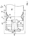
- Fig. 1 shows a simplified cross-section of a gas turbine combustion system incorporating an embodiment of the present invention.
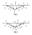
- Fig. 2 is a partial cross-sectional view of the venturi throat region of the combustion system illustrated in Fig. 1 .
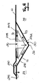
- Fig. 3 is a partial cross-sectional view of a further embodiment of a venturi system for use in a combustion system.
- Fig. 4 is a partial cross-sectional view of still a further embodiment of a venturi system for use in a combustion system.
- the combustor 10 includes a combustion liner 12 that is at least partially surrounded by a heat shield or flow sleeve 14. Compressed air is provided from an upstream compressor (not shown) and fed into a surrounding channel 16 formed between the heat shield 14 and combustion liner 12.
- a plurality of primary fuel nozzles 18 and a secondary fuel nozzle 20 are provided within the confines of the combustion liner 12.
- a combustor flow sleeve 22 is provided surrounding the secondary fuel nozzle 20, separating the secondary nozzle 20 from the primary nozzles 18.
- Fuel 24 is introduced into a controller 26 and fed to the nozzles 18, 20.
- the area between the combustion liner 12 and combustor flow sleeve 22 defines an upstream or primary combustion chamber 28.
- Downstream of the secondary nozzle 20 is a venturi 30 defining an annular restriction within the area defined by the combustion liner 12.
- the venturi 30 includes an apex 32 that defines a venturi throat portion.
- the apex 32 is positioned downstream of the nozzles 18, 20.
- a downstream or secondary combustion chamber 34 is positioned within the combustor downstream of the venturi apex 32.
- flame can reside on either side of the venturi 30, both in the upstream combustion chamber 28 and the downstream combustion chamber 34.
- fuel 24 is provided to the primary nozzles 18, with combustion occurring in the upstream combustion chamber and directed downstream through the venturi throat 32.
- fuel 24 is provided to the primary nozzles 18 as well as to the secondary nozzle 20. Combustion occurs in both the upstream combustion chamber 28 as well as the downstream combustion chamber 34.
- the combustor 10 may operate with fuel 24 directed solely to the secondary nozzle 20, creating combustion in the downstream combustion chamber 34. Additional fuel 24 may be provided to the primary nozzles 18 without flame being created in the upstream combustion chamber 28.
- the fuel and air pre-mix passing through the upstream chamber 28 is directed by the venturi 30 into the downstream combustion chamber 34 creating a pre-mix operation and a significant flame within the downstream chamber 34.
- cooling air in the surrounding channel 16 is directed on to the rear side of the venturi 30 and then directed along the inside walls of the venturi 30.
- the heat load on the upstream and downstream sides of the venturi 30 are contemplated to be different.
- movement of the cooling air back into the combustion chambers on either side of the venturi 30 also has an affect on operation of the combustor 10.
- FIG. 2 there is shown an enlarged schematic cross-sectional view of one side of the venturi 30 illustrated in Fig. 1 .
- Compressed air 36 is directed into a plenum 38 on the back side of the venturi 30.
- the inlet plenum 38 is positioned directly behind the apex 32 of the venturi 30.
- the cooling air directed to the venturi 30 by the inlet plenum is in fluid communication with two channels 40 and 42 that are generally parallel to a first or upstream side 41 of the venturi 30 and a second or downstream side 43 of the venturi 30.
- the cooling air 36 directed into the channel 40 is turned in an opposite direction from the cooling air directed into the channel 42.
- the air flow through the upstream channel 40 on the upstream side 41 of the venturi 30 is directed through an upstream exit 44 and into the primary combustion chamber 28.
- the cooling flow passing through the downstream channel 42 and along the downstream side 43 is directed through exit 46, positioned adjacent the combustion liner 12, and into the downstream combustion chamber 34.
- exit 46 positioned adjacent the combustion liner 12, and into the downstream combustion chamber 34.
- the cooling air 36 is directed from the channel 16 into an inlet plenum 138 having an outlet that is positioned adjacent the downstream side 43 of the venturi 30.
- the inlet plenum 138 is in direct fluid communication with the downstream channel 142. Cooling air is directed in a downstream direction through the channel 142 toward the downstream exit 46. An additional flow of cooling air is directed within the downstream channel portion 142a in the opposite direction from the downstream exit 46. Cooling channel portion 142a communicates with upstream channel 140, positioned behind the upstream side 41 of the venturi 30.
- the cooling air within the upstream channel 140 is directed through the upstream exit 44 and into the upstream combustion chamber 28. Positioning the cooling channel on the downstream face of the venturi reduces the cooling required for the downstream portion of the venturi.
- the inlet plenum 138 may be positioned adjacent the upstream side 41 of the venturi 30.
- the venturi defines a transition between the first and second ends of the combustor.
- the internal passageway within the venturi includes a first side and a second side on opposite sides of an apex of the venturi.
- the cooling inlet for the compressed air flow is in fluid communication with the first and second sides of the venturi passageway and the compressed air from the cooling inlet is directed through the venturi passageway in opposite directions within the first side and second side.
- the cooling inlet may communicate with the venturi passageway at a position in line with or offset from the apex of the venturi.
- the cooling inlet may be formed as a radial plenum positioned behind the venturi or may take any number of other forms.
- a further embodiment of a venturi cooling system is provided.
- the cooling air 36 is directed from the channel 16 into an inlet plenum 238.
- the inlet plenum 238 directs the cooling air into the channels 240, 242 on the rear side of the venturi 30.
- the inlet plenum 238 is positioned adjacent the rear of the apex 32 of the venturi 30, with the upstream channel 240 directing cooling air along the upstream side 41 and the downstream channel 242 directing cooling air along the downstream side 43.
- the downstream end of channel 242 is in fluid communication with a secondary passageway 248. The cooling air within the channel 242 reverses in direction as it enters the secondary passageway 248.
- the secondary passageway 248 extends toward the upstream side of the combustor and joins with the upstream channel 240, adjacent an exhaust channel 250.
- the combined flow from the upstream channel 240 and secondary passageway 248 passes through the exhaust channel 250 and is exhausted through the upstream exit 244 into the combustion chamber 28 on the upstream side of the venturi 30.
- inlet plenum 238 may comprise something other than a continuous slot or annular channel.
- the inlet plenum 238 and secondary passageway 248 may be formed by a series of pipes that cross over one another.
- the inlet plenum 238 feeds the back side of the venturi 30 after crossing over the series of pipes that form the passageway 248.
- Repositioning of the inlet plenum 238 with respect to the axial position of the apex 32 of the venturi 30 may also be utilized to adjust the cooling effect on the venturi 30.
- the relative size and formation of the channels and passageways may be varied so as to adjust the air flow and pressure drop of the cooling air as it moves inside the venturi walls and is then directed into the combustion chambers.
Landscapes
- Engineering & Computer Science (AREA)
- Chemical & Material Sciences (AREA)
- Combustion & Propulsion (AREA)
- Mechanical Engineering (AREA)
- General Engineering & Computer Science (AREA)
- Turbine Rotor Nozzle Sealing (AREA)
- Gas Burners (AREA)
- Spray-Type Burners (AREA)
- Fluidized-Bed Combustion And Resonant Combustion (AREA)
Applications Claiming Priority (1)
| Application Number | Priority Date | Filing Date | Title |
|---|---|---|---|
| US12/357,029 US7712314B1 (en) | 2009-01-21 | 2009-01-21 | Venturi cooling system |
Publications (3)
| Publication Number | Publication Date |
|---|---|
| EP2211104A2 true EP2211104A2 (de) | 2010-07-28 |
| EP2211104A3 EP2211104A3 (de) | 2014-08-06 |
| EP2211104B1 EP2211104B1 (de) | 2017-06-14 |
Family
ID=40566393
Family Applications (1)
| Application Number | Title | Priority Date | Filing Date |
|---|---|---|---|
| EP09004835.6A Active EP2211104B1 (de) | 2009-01-21 | 2009-04-01 | Venturi-Kühlsystem |
Country Status (15)
| Country | Link |
|---|---|
| US (2) | US7712314B1 (de) |
| EP (1) | EP2211104B1 (de) |
| JP (1) | JP4933578B2 (de) |
| KR (1) | KR101131646B1 (de) |
| CN (1) | CN101782232B (de) |
| AR (2) | AR072358A1 (de) |
| AU (1) | AU2009201420B8 (de) |
| BR (1) | BRPI0901605A2 (de) |
| CA (1) | CA2661248C (de) |
| CL (1) | CL2009001101A1 (de) |
| IL (1) | IL198653A (de) |
| MX (1) | MX2009004301A (de) |
| MY (1) | MY149412A (de) |
| SG (2) | SG177888A1 (de) |
| TW (2) | TWI452242B (de) |
Cited By (1)
| Publication number | Priority date | Publication date | Assignee | Title |
|---|---|---|---|---|
| CN109084329A (zh) * | 2018-07-05 | 2018-12-25 | 西北工业大学 | 一种多点直接喷射燃烧室头部结构 |
Families Citing this family (24)
| Publication number | Priority date | Publication date | Assignee | Title |
|---|---|---|---|---|
| US8707704B2 (en) * | 2007-05-31 | 2014-04-29 | General Electric Company | Method and apparatus for assembling turbine engines |
| US8096133B2 (en) * | 2008-05-13 | 2012-01-17 | General Electric Company | Method and apparatus for cooling and dilution tuning a gas turbine combustor liner and transition piece interface |
| US8646277B2 (en) * | 2010-02-19 | 2014-02-11 | General Electric Company | Combustor liner for a turbine engine with venturi and air deflector |
| RU2519014C2 (ru) * | 2010-03-02 | 2014-06-10 | Дженерал Электрик Компани | Диффузор для камеры сгорания турбины (варианты) и камера сгорания турбины |
| US8894363B2 (en) | 2011-02-09 | 2014-11-25 | Siemens Energy, Inc. | Cooling module design and method for cooling components of a gas turbine system |
| US8959886B2 (en) * | 2010-07-08 | 2015-02-24 | Siemens Energy, Inc. | Mesh cooled conduit for conveying combustion gases |
| US20120047895A1 (en) * | 2010-08-26 | 2012-03-01 | General Electric Company | Systems and apparatus relating to combustor cooling and operation in gas turbine engines |
| US9518739B2 (en) | 2013-03-08 | 2016-12-13 | Pratt & Whitney Canada Corp. | Combustor heat shield with carbon avoidance feature |
| US9453424B2 (en) * | 2013-10-21 | 2016-09-27 | Siemens Energy, Inc. | Reverse bulk flow effusion cooling |
| CN104566463B (zh) * | 2014-11-29 | 2016-12-07 | 哈尔滨广瀚燃气轮机有限公司 | 燃气轮机低排放燃烧室空气调节装置 |
| US10100730B2 (en) | 2015-03-11 | 2018-10-16 | Pratt & Whitney Canada Corp. | Secondary air system with venturi |
| CN104807042A (zh) * | 2015-05-15 | 2015-07-29 | 中国航空工业集团公司沈阳发动机设计研究所 | 一种燃烧室 |
| CN105157063B (zh) * | 2015-09-18 | 2018-04-13 | 中国航空工业集团公司沈阳发动机设计研究所 | 一种流量分配可调的火焰筒 |
| CN105465455B (zh) * | 2015-12-25 | 2021-09-07 | 深圳荣钜源科技有限公司 | 出水单元、喷头以及花洒 |
| CN107013941B (zh) * | 2016-01-27 | 2019-09-17 | 中国航发商用航空发动机有限责任公司 | 燃烧室燃油喷嘴装置 |
| US10316803B2 (en) * | 2017-09-25 | 2019-06-11 | Woodward, Inc. | Passive pumping for recirculating exhaust gas |
| US10995705B2 (en) | 2019-02-07 | 2021-05-04 | Woodward, Inc. | Modular exhaust gas recirculation system |
| CN213175878U (zh) | 2020-01-08 | 2021-05-11 | 伍德沃德有限公司 | 排气气体再循环混合器和发动机系统 |
| US11174809B1 (en) | 2020-12-15 | 2021-11-16 | Woodward, Inc. | Controlling an internal combustion engine system |
| US11215132B1 (en) | 2020-12-15 | 2022-01-04 | Woodward, Inc. | Controlling an internal combustion engine system |
| CN116265810B (zh) | 2021-12-16 | 2025-09-26 | 通用电气公司 | 利用成形冷却栅栏的旋流器反稀释 |
| US11835236B1 (en) | 2022-07-05 | 2023-12-05 | General Electric Company | Combustor with reverse dilution air introduction |
| US11747019B1 (en) * | 2022-09-02 | 2023-09-05 | General Electric Company | Aerodynamic combustor liner design for emissions reductions |
| US12416409B2 (en) | 2024-02-08 | 2025-09-16 | General Electric Company | Gas turbine engine having a combustion section with steam provided to second combustor plenum |
Citations (2)
| Publication number | Priority date | Publication date | Assignee | Title |
|---|---|---|---|---|
| US5117636A (en) | 1990-02-05 | 1992-06-02 | General Electric Company | Low nox emission in gas turbine system |
| US6430932B1 (en) | 2001-07-19 | 2002-08-13 | Power Systems Mfg., Llc | Low NOx combustion liner with cooling air plenum recesses |
Family Cites Families (107)
| Publication number | Priority date | Publication date | Assignee | Title |
|---|---|---|---|---|
| US2935841A (en) * | 1956-06-18 | 1960-05-10 | Bell Aircraft Corp | Thrust chamber with integrated cooling and structural members |
| US3656303A (en) | 1970-04-13 | 1972-04-18 | Robert C La Force | Combustion engine pollution control |
| US4010607A (en) | 1973-01-02 | 1977-03-08 | Hopping Alvin S | Internal combustion engine with afterburner, venturi cooler and exhaust turbine |
| US3904307A (en) | 1974-04-10 | 1975-09-09 | United Technologies Corp | Gas generator turbine cooling scheme |
| US3938324A (en) * | 1974-12-12 | 1976-02-17 | General Motors Corporation | Premix combustor with flow constricting baffle between combustion and dilution zones |
| UST962010I4 (en) | 1976-03-25 | 1977-09-06 | Variable venturi carburetor idle speed fuel control | |
| US4250856A (en) | 1980-01-25 | 1981-02-17 | Abbey Harold | Fuel-air ratio automatic control system using variable venturi structure |
| US4200124A (en) | 1978-02-21 | 1980-04-29 | Eaton Corporation | Valve assembly |
| DE7810865U1 (de) | 1978-04-12 | 1978-09-21 | Dolmar Maschinen-Fabrik Gmbh & Co, 2000 Hamburg | Abgasschalldaempfer fuer auspuffvorrichtungen von brennkraftmaschinen, insbesondere von brennkraftmaschinenangetriebenen handarbeitsgeraeten |
| US4303374A (en) | 1978-12-15 | 1981-12-01 | General Electric Company | Film cooled airfoil body |
| US4420929A (en) | 1979-01-12 | 1983-12-20 | General Electric Company | Dual stage-dual mode low emission gas turbine combustion system |
| US4292801A (en) | 1979-07-11 | 1981-10-06 | General Electric Company | Dual stage-dual mode low nox combustor |
| US4361010A (en) * | 1980-04-02 | 1982-11-30 | United Technologies Corporation | Combustor liner construction |
| US4413477A (en) * | 1980-12-29 | 1983-11-08 | General Electric Company | Liner assembly for gas turbine combustor |
| US4690245A (en) | 1983-03-17 | 1987-09-01 | Stemco, Inc. | Flattened venturi, method and apparatus for making |
| US4719748A (en) | 1985-05-14 | 1988-01-19 | General Electric Company | Impingement cooled transition duct |
| US4984429A (en) * | 1986-11-25 | 1991-01-15 | General Electric Company | Impingement cooled liner for dry low NOx venturi combustor |
| US4982570A (en) | 1986-11-25 | 1991-01-08 | General Electric Company | Premixed pilot nozzle for dry low Nox combustor |
| US5329773A (en) | 1989-08-31 | 1994-07-19 | Alliedsignal Inc. | Turbine combustor cooling system |
| US5101624A (en) | 1989-09-07 | 1992-04-07 | General Electric Company | Exhaust nozzle hinge |
| US5285631A (en) | 1990-02-05 | 1994-02-15 | General Electric Company | Low NOx emission in gas turbine system |
| US5123248A (en) | 1990-03-28 | 1992-06-23 | General Electric Company | Low emissions combustor |
| US5127221A (en) | 1990-05-03 | 1992-07-07 | General Electric Company | Transpiration cooled throat section for low nox combustor and related process |
| US5125227A (en) | 1990-07-10 | 1992-06-30 | General Electric Company | Movable combustion system for a gas turbine |
| US5257499A (en) | 1991-09-23 | 1993-11-02 | General Electric Company | Air staged premixed dry low NOx combustor with venturi modulated flow split |
| US5253478A (en) | 1991-12-30 | 1993-10-19 | General Electric Company | Flame holding diverging centerbody cup construction for a dry low NOx combustor |
| US5487275A (en) | 1992-12-11 | 1996-01-30 | General Electric Co. | Tertiary fuel injection system for use in a dry low NOx combustion system |
| US5377483A (en) | 1993-07-07 | 1995-01-03 | Mowill; R. Jan | Process for single stage premixed constant fuel/air ratio combustion |
| US5454221A (en) | 1994-03-14 | 1995-10-03 | General Electric Company | Dilution flow sleeve for reducing emissions in a gas turbine combustor |
| SE504431C2 (sv) | 1994-06-29 | 1997-02-10 | Iggesund Tools Ab | Knivanordning |
| US5584651A (en) | 1994-10-31 | 1996-12-17 | General Electric Company | Cooled shroud |
| US5612006A (en) | 1995-07-05 | 1997-03-18 | Fisk; James C. | Catalytic converter and phase-spreading spiral muffler assembly |
| JP3619599B2 (ja) | 1995-11-30 | 2005-02-09 | 株式会社東芝 | ガスタービンプラント |
| GB2311596B (en) | 1996-03-29 | 2000-07-12 | Europ Gas Turbines Ltd | Combustor for gas - or liquid - fuelled turbine |
| US5787703A (en) | 1996-05-10 | 1998-08-04 | Fougerousse; Russell | Combined ramjet and rocket engine having rectilinear duct |
| US5950417A (en) | 1996-07-19 | 1999-09-14 | Foster Wheeler Energy International Inc. | Topping combustor for low oxygen vitiated air streams |
| US6250066B1 (en) | 1996-11-26 | 2001-06-26 | Honeywell International Inc. | Combustor with dilution bypass system and venturi jet deflector |
| US5829245A (en) | 1996-12-31 | 1998-11-03 | Westinghouse Electric Corporation | Cooling system for gas turbine vane |
| US5738493A (en) | 1997-01-03 | 1998-04-14 | General Electric Company | Turbulator configuration for cooling passages of an airfoil in a gas turbine engine |
| US5896742A (en) | 1997-03-20 | 1999-04-27 | General Electric Co. | Tapered cross-fire tube for gas turbine combustors |
| US6139257A (en) | 1998-03-23 | 2000-10-31 | General Electric Company | Shroud cooling assembly for gas turbine engine |
| CA2288557C (en) | 1998-11-12 | 2007-02-06 | Mitsubishi Heavy Industries, Ltd. | Gas turbine combustor cooling structure |
| GB2345942B (en) | 1998-12-24 | 2002-08-07 | Rolls Royce Plc | Gas turbine engine internal air system |
| RU2158841C2 (ru) * | 1999-01-21 | 2000-11-10 | Открытое акционерное общество "НПО Энергомаш им. акад. В.П. Глушко" | Камера жидкостного ракетного двигателя и ее корпус |
| US6925809B2 (en) | 1999-02-26 | 2005-08-09 | R. Jan Mowill | Gas turbine engine fuel/air premixers with variable geometry exit and method for controlling exit velocities |
| DE19912365A1 (de) | 1999-03-19 | 2000-09-21 | Roche Diagnostics Gmbh | Mehrschichtiges analytisches Hilfsmittel |
| US6037684A (en) | 1999-04-28 | 2000-03-14 | Campbell Haufeld/Scott Fetzer Company | HVLP motor assembly |
| GB9926257D0 (en) | 1999-11-06 | 2000-01-12 | Rolls Royce Plc | Wall elements for gas turbine engine combustors |
| US6267106B1 (en) | 1999-11-09 | 2001-07-31 | Caterpillar Inc. | Induction venturi for an exhaust gas recirculation system in an internal combustion engine |
| DE10019437A1 (de) | 2000-04-19 | 2001-12-20 | Rolls Royce Deutschland | Verfahren und Vorrichtung zum Kühlen der Gehäuse von Turbinen von Strahltriebwerken |
| US6446438B1 (en) | 2000-06-28 | 2002-09-10 | Power Systems Mfg., Llc | Combustion chamber/venturi cooling for a low NOx emission combustor |
| WO2003093664A1 (en) * | 2000-06-28 | 2003-11-13 | Power Systems Mfg. Llc | Combustion chamber/venturi cooling for a low nox emission combustor |
| US6374594B1 (en) | 2000-07-12 | 2002-04-23 | Power Systems Mfg., Llc | Silo/can-annular low emissions combustor |
| US6427446B1 (en) | 2000-09-19 | 2002-08-06 | Power Systems Mfg., Llc | Low NOx emission combustion liner with circumferentially angled film cooling holes |
| US6672570B2 (en) | 2000-11-17 | 2004-01-06 | Walbro Japan, Inc. | Variable venturi carburetor |
| US6536201B2 (en) | 2000-12-11 | 2003-03-25 | Pratt & Whitney Canada Corp. | Combustor turbine successive dual cooling |
| US6623160B2 (en) | 2000-12-21 | 2003-09-23 | Mccarthy, Jr. Joseph H. | Method and system for cooling heat-generating component in a closed-loop system |
| US6698924B2 (en) | 2000-12-21 | 2004-03-02 | Tank, Inc. | Cooling system comprising a circular venturi |
| FR2836986B1 (fr) | 2002-03-07 | 2004-11-19 | Snecma Moteurs | Systeme d'injection multi-modes d'un melange air/carburant dans une chambre de combustion |
| US6705088B2 (en) | 2002-04-05 | 2004-03-16 | Power Systems Mfg, Llc | Advanced crossfire tube cooling scheme for gas turbine combustors |
| US6772595B2 (en) | 2002-06-25 | 2004-08-10 | Power Systems Mfg., Llc | Advanced cooling configuration for a low emissions combustor venturi |
| US6832482B2 (en) | 2002-06-25 | 2004-12-21 | Power Systems Mfg, Llc | Pressure ram device on a gas turbine combustor |
| US6675581B1 (en) | 2002-07-15 | 2004-01-13 | Power Systems Mfg, Llc | Fully premixed secondary fuel nozzle |
| US6898937B2 (en) | 2002-07-15 | 2005-05-31 | Power Systems Mfg., Llc | Gas only fin mixer secondary fuel nozzle |
| US6691516B2 (en) | 2002-07-15 | 2004-02-17 | Power Systems Mfg, Llc | Fully premixed secondary fuel nozzle with improved stability |
| US7290394B2 (en) | 2002-11-21 | 2007-11-06 | Parker-Hannifin Corporation | Fuel injector flexible feed with moveable nozzle tip |
| US6969230B2 (en) | 2002-12-17 | 2005-11-29 | General Electric Company | Venturi outlet turbine airfoil |
| US6865892B2 (en) * | 2002-12-17 | 2005-03-15 | Power Systems Mfg, Llc | Combustion chamber/venturi configuration and assembly method |
| DE602004027993D1 (de) | 2003-02-24 | 2010-08-19 | Pratt & Whitney Canada | Eingebautes kühlsystem für einen umlaufmotor |
| US6912838B2 (en) | 2003-03-06 | 2005-07-05 | Power Systems Mfg, Llc | Coated crossfire tube assembly |
| US6981846B2 (en) | 2003-03-12 | 2006-01-03 | Florida Turbine Technologies, Inc. | Vortex cooling of turbine blades |
| US6935116B2 (en) | 2003-04-28 | 2005-08-30 | Power Systems Mfg., Llc | Flamesheet combustor |
| US6986254B2 (en) | 2003-05-14 | 2006-01-17 | Power Systems Mfg, Llc | Method of operating a flamesheet combustor |
| US7051524B1 (en) | 2003-06-30 | 2006-05-30 | Bernard A Kraft | Venturi device |
| JP4040556B2 (ja) | 2003-09-04 | 2008-01-30 | 株式会社日立製作所 | ガスタービン設備及び冷却空気供給方法 |
| US7021892B2 (en) | 2003-11-19 | 2006-04-04 | Massachusetts Institute Of Technology | Method for assembling gas turbine engine components |
| US7096668B2 (en) | 2003-12-22 | 2006-08-29 | Martling Vincent C | Cooling and sealing design for a gas turbine combustion system |
| US7082770B2 (en) | 2003-12-24 | 2006-08-01 | Martling Vincent C | Flow sleeve for a low NOx combustor |
| US6951109B2 (en) | 2004-01-06 | 2005-10-04 | General Electric Company | Apparatus and methods for minimizing and/or eliminating dilution air leakage in a combustion liner assembly |
| JP4495603B2 (ja) | 2004-01-15 | 2010-07-07 | 株式会社日立製作所 | ガスタービン発電装置およびそれに用いる消音装置 |
| US7127899B2 (en) | 2004-02-26 | 2006-10-31 | United Technologies Corporation | Non-swirl dry low NOx (DLN) combustor |
| US7013649B2 (en) | 2004-05-25 | 2006-03-21 | General Electric Company | Gas turbine engine combustor mixer |
| US7007482B2 (en) | 2004-05-28 | 2006-03-07 | Power Systems Mfg., Llc | Combustion liner seal with heat transfer augmentation |
| US7152410B2 (en) | 2004-06-10 | 2006-12-26 | Honeywell International, Inc. | System and method for dumping surge flow into eductor primary nozzle for free turbine |
| US6983600B1 (en) | 2004-06-30 | 2006-01-10 | General Electric Company | Multi-venturi tube fuel injector for gas turbine combustors |
| US7003958B2 (en) | 2004-06-30 | 2006-02-28 | General Electric Company | Multi-sided diffuser for a venturi in a fuel injector for a gas turbine |
| EP1769147B1 (de) | 2004-07-19 | 2009-07-29 | Alstom Technology Ltd | Verfahren zum betrieb einer gasturbogruppe |
| US7153488B2 (en) | 2004-08-03 | 2006-12-26 | Millennium Inorganic Chemicals, Inc. | Suppression of the formation of noxious substances during chloride processes |
| US20060042257A1 (en) | 2004-08-27 | 2006-03-02 | Pratt & Whitney Canada Corp. | Combustor heat shield and method of cooling |
| US7237384B2 (en) | 2005-01-26 | 2007-07-03 | Peter Stuttaford | Counter swirl shear mixer |
| US7389643B2 (en) * | 2005-01-31 | 2008-06-24 | General Electric Company | Inboard radial dump venturi for combustion chamber of a gas turbine |
| US7677025B2 (en) | 2005-02-01 | 2010-03-16 | Power Systems Mfg., Llc | Self-purging pilot fuel injection system |
| US7386980B2 (en) | 2005-02-02 | 2008-06-17 | Power Systems Mfg., Llc | Combustion liner with enhanced heat transfer |
| US7513115B2 (en) | 2005-05-23 | 2009-04-07 | Power Systems Mfg., Llc | Flashback suppression system for a gas turbine combustor |
| US7451600B2 (en) | 2005-07-06 | 2008-11-18 | Pratt & Whitney Canada Corp. | Gas turbine engine combustor with improved cooling |
| CN1932316B (zh) | 2005-09-16 | 2010-09-29 | 深圳富泰宏精密工业有限公司 | 多段式转轴结构 |
| US7559203B2 (en) | 2005-09-16 | 2009-07-14 | Pratt & Whitney Canada Corp. | Cooled support boss for a combustor in a gas turbine engine |
| US7546737B2 (en) | 2006-01-24 | 2009-06-16 | Honeywell International Inc. | Segmented effusion cooled gas turbine engine combustor |
| FR2897107B1 (fr) | 2006-02-09 | 2013-01-18 | Snecma | Paroi transversale de chambre de combustion munie de trous de multiperforation |
| US7770395B2 (en) | 2006-02-27 | 2010-08-10 | Mitsubishi Heavy Industries, Ltd. | Combustor |
| US7624577B2 (en) | 2006-03-31 | 2009-12-01 | Pratt & Whitney Canada Corp. | Gas turbine engine combustor with improved cooling |
| US8109098B2 (en) | 2006-05-04 | 2012-02-07 | Siemens Energy, Inc. | Combustor liner for gas turbine engine |
| US7669411B2 (en) | 2006-05-10 | 2010-03-02 | Caterpillar Inc. | Cooling device |
| FR2904048B1 (fr) | 2006-07-19 | 2012-12-14 | Snecma | Systeme de ventilation de paroi de chambre de combustion dans une turbomachine |
| US7631503B2 (en) | 2006-09-12 | 2009-12-15 | Pratt & Whitney Canada Corp. | Combustor with enhanced cooling access |
| US8182199B2 (en) | 2007-02-01 | 2012-05-22 | Pratt & Whitney Canada Corp. | Turbine shroud cooling system |
| US20090019854A1 (en) | 2007-07-16 | 2009-01-22 | General Electric Company | APPARATUS/METHOD FOR COOLING COMBUSTION CHAMBER/VENTURI IN A LOW NOx COMBUSTOR |
-
2009
- 2009-01-21 US US12/357,029 patent/US7712314B1/en active Active
- 2009-04-01 EP EP09004835.6A patent/EP2211104B1/de active Active
- 2009-04-02 SG SG2011091501A patent/SG177888A1/en unknown
- 2009-04-02 CA CA2661248A patent/CA2661248C/en active Active
- 2009-04-02 SG SG200902292-2A patent/SG163466A1/en unknown
- 2009-04-08 AU AU2009201420A patent/AU2009201420B8/en active Active
- 2009-04-22 MX MX2009004301A patent/MX2009004301A/es active IP Right Grant
- 2009-04-28 JP JP2009110007A patent/JP4933578B2/ja active Active
- 2009-05-05 CN CN2009101359487A patent/CN101782232B/zh active Active
- 2009-05-05 AR ARP090101612A patent/AR072358A1/es active IP Right Grant
- 2009-05-07 MY MYPI20091855A patent/MY149412A/en unknown
- 2009-05-07 CL CL2009001101A patent/CL2009001101A1/es unknown
- 2009-05-07 IL IL198653A patent/IL198653A/en active IP Right Grant
- 2009-05-07 BR BRPI0901605-8A patent/BRPI0901605A2/pt not_active Application Discontinuation
- 2009-05-08 KR KR1020090040209A patent/KR101131646B1/ko active Active
- 2009-05-11 TW TW101113646A patent/TWI452242B/zh active
- 2009-05-11 TW TW098115593A patent/TWI376484B/zh active
- 2009-08-06 US US12/536,861 patent/US7707836B1/en active Active
-
2013
- 2013-10-04 AR ARP130103609A patent/AR092910A2/es active IP Right Grant
Patent Citations (2)
| Publication number | Priority date | Publication date | Assignee | Title |
|---|---|---|---|---|
| US5117636A (en) | 1990-02-05 | 1992-06-02 | General Electric Company | Low nox emission in gas turbine system |
| US6430932B1 (en) | 2001-07-19 | 2002-08-13 | Power Systems Mfg., Llc | Low NOx combustion liner with cooling air plenum recesses |
Cited By (1)
| Publication number | Priority date | Publication date | Assignee | Title |
|---|---|---|---|---|
| CN109084329A (zh) * | 2018-07-05 | 2018-12-25 | 西北工业大学 | 一种多点直接喷射燃烧室头部结构 |
Also Published As
| Publication number | Publication date |
|---|---|
| AU2009201420A1 (en) | 2010-08-05 |
| KR20100085810A (ko) | 2010-07-29 |
| TWI376484B (en) | 2012-11-11 |
| IL198653A (en) | 2013-01-31 |
| AU2009201420B8 (en) | 2011-02-17 |
| JP2010169076A (ja) | 2010-08-05 |
| US7712314B1 (en) | 2010-05-11 |
| TW201241369A (en) | 2012-10-16 |
| MY149412A (en) | 2013-08-30 |
| AR072358A1 (es) | 2010-08-25 |
| EP2211104B1 (de) | 2017-06-14 |
| SG163466A1 (en) | 2010-08-30 |
| BRPI0901605A2 (pt) | 2010-12-21 |
| TW201028622A (en) | 2010-08-01 |
| EP2211104A3 (de) | 2014-08-06 |
| IL198653A0 (en) | 2010-02-17 |
| CN101782232A (zh) | 2010-07-21 |
| MX2009004301A (es) | 2010-07-20 |
| AU2009201420B2 (en) | 2011-01-27 |
| CA2661248C (en) | 2011-02-08 |
| CA2661248A1 (en) | 2010-07-21 |
| CL2009001101A1 (es) | 2011-08-19 |
| JP4933578B2 (ja) | 2012-05-16 |
| SG177888A1 (en) | 2012-02-28 |
| AR092910A2 (es) | 2015-05-06 |
| TWI452242B (zh) | 2014-09-11 |
| CN101782232B (zh) | 2012-11-28 |
| US7707836B1 (en) | 2010-05-04 |
| HK1146108A1 (en) | 2011-05-13 |
| KR101131646B1 (ko) | 2012-03-28 |
Similar Documents
| Publication | Publication Date | Title |
|---|---|---|
| CA2661248C (en) | Venturi cooling system | |
| KR102334882B1 (ko) | 패널 연료 분사기를 갖는 연소 시스템 | |
| US12085281B2 (en) | Fuel nozzle and swirler | |
| EP4202302A1 (de) | Brennstoffdüse und verwirbler | |
| JP2016041929A (ja) | 燃焼タービンエンジンの燃料噴射器組立体 | |
| JP4997018B2 (ja) | 一次燃料噴射器及び複数の二次燃料噴射ポートを有するガスタービンエンジン燃焼器のミキサ組立体のためのパイロットミキサ | |
| US20230194091A1 (en) | Gas turbine fuel nozzle having a fuel passage within a swirler | |
| KR101774630B1 (ko) | 가스 터빈 엔진에 사용되는 예비혼합된 연료와 공기를 가진 접선방향의 애뉼러형 연소실 | |
| JP5052783B2 (ja) | ガスタービンエンジンおよび燃料供給装置 | |
| EP4206534B1 (de) | Vormischer für einen turbinenmotor | |
| US11906165B2 (en) | Gas turbine nozzle having an inner air swirler passage and plural exterior fuel passages | |
| KR101774094B1 (ko) | 가스 터빈 엔진에서 사용되는 예비혼합형 접선방향 연료-공기 노즐을 가진 캔-애뉼러형 연소실 | |
| CN116518417A (zh) | 具有燃料喷射器的燃烧器 | |
| US20250251133A1 (en) | Turbine engine having a combustion section with a fuel supply assembly | |
| HK1146108B (en) | Venturi cooling system | |
| CA2572044C (en) | Combustor construction | |
| CA2596789A1 (en) | Pilot mixer for mixer assembly of a gas turbine engine combustor having a primary fuel injector and a plurality of secondary fuel injection ports |
Legal Events
| Date | Code | Title | Description |
|---|---|---|---|
| PUAI | Public reference made under article 153(3) epc to a published international application that has entered the european phase |
Free format text: ORIGINAL CODE: 0009012 |
|
| 17P | Request for examination filed |
Effective date: 20090401 |
|
| AK | Designated contracting states |
Kind code of ref document: A2 Designated state(s): AT BE BG CH CY CZ DE DK EE ES FI FR GB GR HR HU IE IS IT LI LT LU LV MC MK MT NL NO PL PT RO SE SI SK TR |
|
| AX | Request for extension of the european patent |
Extension state: AL BA RS |
|
| PUAL | Search report despatched |
Free format text: ORIGINAL CODE: 0009013 |
|
| AK | Designated contracting states |
Kind code of ref document: A3 Designated state(s): AT BE BG CH CY CZ DE DK EE ES FI FR GB GR HR HU IE IS IT LI LT LU LV MC MK MT NL NO PL PT RO SE SI SK TR |
|
| AX | Request for extension of the european patent |
Extension state: AL BA RS |
|
| RIC1 | Information provided on ipc code assigned before grant |
Ipc: F23R 3/04 20060101ALI20140701BHEP Ipc: F23R 3/00 20060101AFI20140701BHEP Ipc: F23R 3/42 20060101ALI20140701BHEP |
|
| GRAP | Despatch of communication of intention to grant a patent |
Free format text: ORIGINAL CODE: EPIDOSNIGR1 |
|
| STAA | Information on the status of an ep patent application or granted ep patent |
Free format text: STATUS: GRANT OF PATENT IS INTENDED |
|
| INTG | Intention to grant announced |
Effective date: 20170210 |
|
| RAP1 | Party data changed (applicant data changed or rights of an application transferred) |
Owner name: GAS TURBINE EFFICIENCY SWEDEN AB |
|
| GRAS | Grant fee paid |
Free format text: ORIGINAL CODE: EPIDOSNIGR3 |
|
| GRAA | (expected) grant |
Free format text: ORIGINAL CODE: 0009210 |
|
| STAA | Information on the status of an ep patent application or granted ep patent |
Free format text: STATUS: THE PATENT HAS BEEN GRANTED |
|
| AK | Designated contracting states |
Kind code of ref document: B1 Designated state(s): AT BE BG CH CY CZ DE DK EE ES FI FR GB GR HR HU IE IS IT LI LT LU LV MC MK MT NL NO PL PT RO SE SI SK TR |
|
| REG | Reference to a national code |
Ref country code: GB Ref legal event code: FG4D |
|
| REG | Reference to a national code |
Ref country code: CH Ref legal event code: EP Ref country code: AT Ref legal event code: REF Ref document number: 901350 Country of ref document: AT Kind code of ref document: T Effective date: 20170615 |
|
| REG | Reference to a national code |
Ref country code: IE Ref legal event code: FG4D |
|
| REG | Reference to a national code |
Ref country code: DE Ref legal event code: R096 Ref document number: 602009046574 Country of ref document: DE |
|
| REG | Reference to a national code |
Ref country code: SE Ref legal event code: TRGR |
|
| REG | Reference to a national code |
Ref country code: CH Ref legal event code: NV Representative=s name: KASCHE AND PARTNER AG, CH |
|
| REG | Reference to a national code |
Ref country code: NL Ref legal event code: MP Effective date: 20170614 |
|
| REG | Reference to a national code |
Ref country code: LT Ref legal event code: MG4D |
|
| PG25 | Lapsed in a contracting state [announced via postgrant information from national office to epo] |
Ref country code: ES Free format text: LAPSE BECAUSE OF FAILURE TO SUBMIT A TRANSLATION OF THE DESCRIPTION OR TO PAY THE FEE WITHIN THE PRESCRIBED TIME-LIMIT Effective date: 20170614 Ref country code: GR Free format text: LAPSE BECAUSE OF FAILURE TO SUBMIT A TRANSLATION OF THE DESCRIPTION OR TO PAY THE FEE WITHIN THE PRESCRIBED TIME-LIMIT Effective date: 20170915 Ref country code: FI Free format text: LAPSE BECAUSE OF FAILURE TO SUBMIT A TRANSLATION OF THE DESCRIPTION OR TO PAY THE FEE WITHIN THE PRESCRIBED TIME-LIMIT Effective date: 20170614 Ref country code: NO Free format text: LAPSE BECAUSE OF FAILURE TO SUBMIT A TRANSLATION OF THE DESCRIPTION OR TO PAY THE FEE WITHIN THE PRESCRIBED TIME-LIMIT Effective date: 20170914 Ref country code: HR Free format text: LAPSE BECAUSE OF FAILURE TO SUBMIT A TRANSLATION OF THE DESCRIPTION OR TO PAY THE FEE WITHIN THE PRESCRIBED TIME-LIMIT Effective date: 20170614 Ref country code: LT Free format text: LAPSE BECAUSE OF FAILURE TO SUBMIT A TRANSLATION OF THE DESCRIPTION OR TO PAY THE FEE WITHIN THE PRESCRIBED TIME-LIMIT Effective date: 20170614 |
|
| REG | Reference to a national code |
Ref country code: AT Ref legal event code: MK05 Ref document number: 901350 Country of ref document: AT Kind code of ref document: T Effective date: 20170614 |
|
| PG25 | Lapsed in a contracting state [announced via postgrant information from national office to epo] |
Ref country code: NL Free format text: LAPSE BECAUSE OF FAILURE TO SUBMIT A TRANSLATION OF THE DESCRIPTION OR TO PAY THE FEE WITHIN THE PRESCRIBED TIME-LIMIT Effective date: 20170614 Ref country code: LV Free format text: LAPSE BECAUSE OF FAILURE TO SUBMIT A TRANSLATION OF THE DESCRIPTION OR TO PAY THE FEE WITHIN THE PRESCRIBED TIME-LIMIT Effective date: 20170614 Ref country code: BG Free format text: LAPSE BECAUSE OF FAILURE TO SUBMIT A TRANSLATION OF THE DESCRIPTION OR TO PAY THE FEE WITHIN THE PRESCRIBED TIME-LIMIT Effective date: 20170914 |
|
| PG25 | Lapsed in a contracting state [announced via postgrant information from national office to epo] |
Ref country code: EE Free format text: LAPSE BECAUSE OF FAILURE TO SUBMIT A TRANSLATION OF THE DESCRIPTION OR TO PAY THE FEE WITHIN THE PRESCRIBED TIME-LIMIT Effective date: 20170614 Ref country code: CZ Free format text: LAPSE BECAUSE OF FAILURE TO SUBMIT A TRANSLATION OF THE DESCRIPTION OR TO PAY THE FEE WITHIN THE PRESCRIBED TIME-LIMIT Effective date: 20170614 Ref country code: RO Free format text: LAPSE BECAUSE OF FAILURE TO SUBMIT A TRANSLATION OF THE DESCRIPTION OR TO PAY THE FEE WITHIN THE PRESCRIBED TIME-LIMIT Effective date: 20170614 Ref country code: SK Free format text: LAPSE BECAUSE OF FAILURE TO SUBMIT A TRANSLATION OF THE DESCRIPTION OR TO PAY THE FEE WITHIN THE PRESCRIBED TIME-LIMIT Effective date: 20170614 Ref country code: AT Free format text: LAPSE BECAUSE OF FAILURE TO SUBMIT A TRANSLATION OF THE DESCRIPTION OR TO PAY THE FEE WITHIN THE PRESCRIBED TIME-LIMIT Effective date: 20170614 |
|
| PG25 | Lapsed in a contracting state [announced via postgrant information from national office to epo] |
Ref country code: IS Free format text: LAPSE BECAUSE OF FAILURE TO SUBMIT A TRANSLATION OF THE DESCRIPTION OR TO PAY THE FEE WITHIN THE PRESCRIBED TIME-LIMIT Effective date: 20171014 Ref country code: PL Free format text: LAPSE BECAUSE OF FAILURE TO SUBMIT A TRANSLATION OF THE DESCRIPTION OR TO PAY THE FEE WITHIN THE PRESCRIBED TIME-LIMIT Effective date: 20170614 |
|
| REG | Reference to a national code |
Ref country code: DE Ref legal event code: R097 Ref document number: 602009046574 Country of ref document: DE |
|
| PLBE | No opposition filed within time limit |
Free format text: ORIGINAL CODE: 0009261 |
|
| STAA | Information on the status of an ep patent application or granted ep patent |
Free format text: STATUS: NO OPPOSITION FILED WITHIN TIME LIMIT |
|
| REG | Reference to a national code |
Ref country code: FR Ref legal event code: PLFP Year of fee payment: 10 |
|
| PG25 | Lapsed in a contracting state [announced via postgrant information from national office to epo] |
Ref country code: DK Free format text: LAPSE BECAUSE OF FAILURE TO SUBMIT A TRANSLATION OF THE DESCRIPTION OR TO PAY THE FEE WITHIN THE PRESCRIBED TIME-LIMIT Effective date: 20170614 |
|
| 26N | No opposition filed |
Effective date: 20180315 |
|
| PG25 | Lapsed in a contracting state [announced via postgrant information from national office to epo] |
Ref country code: SI Free format text: LAPSE BECAUSE OF FAILURE TO SUBMIT A TRANSLATION OF THE DESCRIPTION OR TO PAY THE FEE WITHIN THE PRESCRIBED TIME-LIMIT Effective date: 20170614 |
|
| PG25 | Lapsed in a contracting state [announced via postgrant information from national office to epo] |
Ref country code: MC Free format text: LAPSE BECAUSE OF FAILURE TO SUBMIT A TRANSLATION OF THE DESCRIPTION OR TO PAY THE FEE WITHIN THE PRESCRIBED TIME-LIMIT Effective date: 20170614 |
|
| REG | Reference to a national code |
Ref country code: BE Ref legal event code: MM Effective date: 20180430 |
|
| REG | Reference to a national code |
Ref country code: IE Ref legal event code: MM4A |
|
| PG25 | Lapsed in a contracting state [announced via postgrant information from national office to epo] |
Ref country code: LU Free format text: LAPSE BECAUSE OF NON-PAYMENT OF DUE FEES Effective date: 20180401 |
|
| PG25 | Lapsed in a contracting state [announced via postgrant information from national office to epo] |
Ref country code: BE Free format text: LAPSE BECAUSE OF NON-PAYMENT OF DUE FEES Effective date: 20180430 |
|
| PG25 | Lapsed in a contracting state [announced via postgrant information from national office to epo] |
Ref country code: IE Free format text: LAPSE BECAUSE OF NON-PAYMENT OF DUE FEES Effective date: 20180401 |
|
| PG25 | Lapsed in a contracting state [announced via postgrant information from national office to epo] |
Ref country code: MT Free format text: LAPSE BECAUSE OF NON-PAYMENT OF DUE FEES Effective date: 20180401 |
|
| PG25 | Lapsed in a contracting state [announced via postgrant information from national office to epo] |
Ref country code: TR Free format text: LAPSE BECAUSE OF FAILURE TO SUBMIT A TRANSLATION OF THE DESCRIPTION OR TO PAY THE FEE WITHIN THE PRESCRIBED TIME-LIMIT Effective date: 20170614 |
|
| PG25 | Lapsed in a contracting state [announced via postgrant information from national office to epo] |
Ref country code: HU Free format text: LAPSE BECAUSE OF FAILURE TO SUBMIT A TRANSLATION OF THE DESCRIPTION OR TO PAY THE FEE WITHIN THE PRESCRIBED TIME-LIMIT; INVALID AB INITIO Effective date: 20090401 Ref country code: PT Free format text: LAPSE BECAUSE OF FAILURE TO SUBMIT A TRANSLATION OF THE DESCRIPTION OR TO PAY THE FEE WITHIN THE PRESCRIBED TIME-LIMIT Effective date: 20170614 |
|
| PG25 | Lapsed in a contracting state [announced via postgrant information from national office to epo] |
Ref country code: MK Free format text: LAPSE BECAUSE OF NON-PAYMENT OF DUE FEES Effective date: 20170614 Ref country code: CY Free format text: LAPSE BECAUSE OF FAILURE TO SUBMIT A TRANSLATION OF THE DESCRIPTION OR TO PAY THE FEE WITHIN THE PRESCRIBED TIME-LIMIT Effective date: 20170614 |
|
| P01 | Opt-out of the competence of the unified patent court (upc) registered |
Effective date: 20230505 |
|
| PGFP | Annual fee paid to national office [announced via postgrant information from national office to epo] |
Ref country code: DE Payment date: 20250424 Year of fee payment: 17 |
|
| PGFP | Annual fee paid to national office [announced via postgrant information from national office to epo] |
Ref country code: IT Payment date: 20250430 Year of fee payment: 17 |
|
| PGFP | Annual fee paid to national office [announced via postgrant information from national office to epo] |
Ref country code: FR Payment date: 20250425 Year of fee payment: 17 |
|
| PGFP | Annual fee paid to national office [announced via postgrant information from national office to epo] |
Ref country code: CH Payment date: 20250501 Year of fee payment: 17 |
|
| PGFP | Annual fee paid to national office [announced via postgrant information from national office to epo] |
Ref country code: SE Payment date: 20250423 Year of fee payment: 17 |
|
| REG | Reference to a national code |
Ref country code: CH Ref legal event code: R17 Free format text: ST27 STATUS EVENT CODE: U-0-0-R10-R17 (AS PROVIDED BY THE NATIONAL OFFICE) Effective date: 20251212 |
|
| PGFP | Annual fee paid to national office [announced via postgrant information from national office to epo] |
Ref country code: GB Payment date: 20260327 Year of fee payment: 18 |
|
| REG | Reference to a national code |
Ref country code: CH Ref legal event code: U11 Free format text: ST27 STATUS EVENT CODE: U-0-0-U10-U11 (AS PROVIDED BY THE NATIONAL OFFICE) Effective date: 20260501 |