EP2211154B1 - Monochromateur à réseau accordable - Google Patents
Monochromateur à réseau accordable Download PDFInfo
- Publication number
- EP2211154B1 EP2211154B1 EP09151155.0A EP09151155A EP2211154B1 EP 2211154 B1 EP2211154 B1 EP 2211154B1 EP 09151155 A EP09151155 A EP 09151155A EP 2211154 B1 EP2211154 B1 EP 2211154B1
- Authority
- EP
- European Patent Office
- Prior art keywords
- grating
- collimated
- wavelength
- narrow band
- light
- Prior art date
- Legal status (The legal status is an assumption and is not a legal conclusion. Google has not performed a legal analysis and makes no representation as to the accuracy of the status listed.)
- Not-in-force
Links
Images


Classifications
-
- G—PHYSICS
- G01—MEASURING; TESTING
- G01J—MEASUREMENT OF INTENSITY, VELOCITY, SPECTRAL CONTENT, POLARISATION, PHASE OR PULSE CHARACTERISTICS OF INFRARED, VISIBLE OR ULTRAVIOLET LIGHT; COLORIMETRY; RADIATION PYROMETRY
- G01J3/00—Spectrometry; Spectrophotometry; Monochromators; Measuring colours
- G01J3/12—Generating the spectrum; Monochromators
- G01J3/18—Generating the spectrum; Monochromators using diffraction elements, e.g. grating
- G01J3/1804—Plane gratings
-
- G—PHYSICS
- G01—MEASURING; TESTING
- G01J—MEASUREMENT OF INTENSITY, VELOCITY, SPECTRAL CONTENT, POLARISATION, PHASE OR PULSE CHARACTERISTICS OF INFRARED, VISIBLE OR ULTRAVIOLET LIGHT; COLORIMETRY; RADIATION PYROMETRY
- G01J3/00—Spectrometry; Spectrophotometry; Monochromators; Measuring colours
- G01J3/02—Details
-
- G—PHYSICS
- G01—MEASURING; TESTING
- G01J—MEASUREMENT OF INTENSITY, VELOCITY, SPECTRAL CONTENT, POLARISATION, PHASE OR PULSE CHARACTERISTICS OF INFRARED, VISIBLE OR ULTRAVIOLET LIGHT; COLORIMETRY; RADIATION PYROMETRY
- G01J3/00—Spectrometry; Spectrophotometry; Monochromators; Measuring colours
- G01J3/02—Details
- G01J3/0205—Optical elements not provided otherwise, e.g. optical manifolds, diffusers, windows
- G01J3/0237—Adjustable, e.g. focussing
-
- G—PHYSICS
- G01—MEASURING; TESTING
- G01J—MEASUREMENT OF INTENSITY, VELOCITY, SPECTRAL CONTENT, POLARISATION, PHASE OR PULSE CHARACTERISTICS OF INFRARED, VISIBLE OR ULTRAVIOLET LIGHT; COLORIMETRY; RADIATION PYROMETRY
- G01J3/00—Spectrometry; Spectrophotometry; Monochromators; Measuring colours
- G01J3/28—Investigating the spectrum
- G01J3/30—Measuring the intensity of spectral lines directly on the spectrum itself
- G01J3/32—Investigating bands of a spectrum in sequence by a single detector
-
- G—PHYSICS
- G02—OPTICS
- G02B—OPTICAL ELEMENTS, SYSTEMS OR APPARATUS
- G02B5/00—Optical elements other than lenses
- G02B5/18—Diffraction gratings
- G02B5/1828—Diffraction gratings having means for producing variable diffraction
Definitions
- the present invention relates generally to the field of spectroscopy, more particularly to the field of monochromators comprising a grating.
- the purpose of a monochromator is to analyse the spectrum of an input light, by separating the narrow bands of wavelengths composing the input light.
- These monochromators could be used for example in a spectrometer in order to analyse the spectrum of the light reflected by a sample and to obtain quantitative and/or qualitative information about this sample. By identifying and measuring the narrow bands of wavelength of the light reflected by the sample, it is possible to identify and / or quantify the chemical compounds of the sample.
- a monochromator generally comprises:
- a spectrometer can be obtained by adding a light detector, for measuring the wavelengths composing the spectrum.
- the dispersion device can consist in a prism, and the diffraction device can consist in a diffraction grating, working either in transmission or in reflection.
- a light detector measures the intensity of the light projected onto it, and can consist for example in a photodiode.
- the spectrum shall be projected onto an array of light detectors, the using of which being, depending on the considered wavelength range, costly and power-consuming. Additionally, a trade-off between the size and the resolution of the array has to be made. Increasing the number of light detectors improves the resolution but also increases the size of the array of light detectors. The resolution is linked to the number of different narrow bands of wavelength measured, and consequently to the width of the narrowest band of wavelength that can be measured. The resolution is improved when the number of measured bands increases or when the width of the bands decreases.
- the power consumption of the array of light detectors can be high. It could be a concern when designing a handheld spectrometer.
- the second category of spectrometer avoids using an array of light detectors by projecting sequentially each narrow band of wavelength onto a single light detector. It is therefore possible to measure successively the whole spectrum by using only one light detector, and consequently resulting in a compacter, less expensive and less power-consuming spectrometer.
- Different solutions can be used in order to selectively project a narrow band of wavelength onto a single light detector.
- a diffraction grating or a prism is used to generate the spectrum, it is possible to rotate the grating or the prism. This rotation causes the direction of the spectrum to change.
- this solution is difficult to implement since it requires mechanical means in order to rotate the grating.
- it is not possible to diffract or disperse the input light more than once with a single grating.
- a second solution is to project the spectrum onto a microelectromechanical system (MEMS), this MEMS being used to selectively reflect a narrow band or a band of wavelength onto a single light detector.
- MEMS microelectromechanical system
- this solution has the drawback to require one grating and an additional MEMS for the wavelength selection.
- the grating is composed of a plurality of beams, each beam having a tilted reflective flat surface.
- the grating is stretchable, i.e. the distance between the beams is uniformly adjustable.
- An input collimated light is projected onto the grating, following a direction normal to the flat surfaces. This configuration, where the input light and the diffracted light are in auto-collimation is called the Littrow configuration, and is known to produce the best energetic efficiency of the diffraction.
- the present invention proposes a monochromator and its use in a spectrometer in which these drawbacks are avoided.
- this monochromator comprises:
- said collimated input light is arranged to be parallel to a plane P1, said plane P1 being oriented longitudinally to said beams and perpendicular to the first tilted reflective flat surfaces, said collimated input light being projected onto said first tilted surface at an angle ⁇ to the normal N of said first tilted reflective surface and being diffracted by said first grating into a first collimated narrow band of wavelength.
- Said first mirror and second mirror are arranged in order for said first collimated narrow band of wavelength to be parallel to a plane P2 after reflection on the first mirror and on the second mirror, said plane P2 being oriented longitudinally to the longitudinal axis of said beams and perpendicular to the second tilted reflective flat surfaces, said first collimated narrow band of wavelength being projected onto said second tilted surface at an angle ⁇ to the normal N of said second tilted reflective surface and being diffracted by said first grating into a second collimated narrow band of wavelength.
- Figure 1 depicts a spectrometer 1 according to a first preferred embodiment of the present invention.
- the spectrometer 1 comprises:
- the entrance aperture, the tunable step grating 2 and the exit aperture act as a monochromator.
- the step grating 2 comprises a plurality of juxtaposed steps 4, each step having at his top a reflective flat surface 4a.
- the steps are juxtaposed along an axis x.
- the reflective flat surfaces 4a do not overlap and are parallel. They are spaced by a distance d 1 between two consecutive reflective flat surfaces 4a, in the direction of the normal to the flat surfaces 4a. This distance d 1 is the same for the whole grating 2 and is tunable.
- An input collimated light 5 is projected onto the grating 2, in a direction parallel to a plan P, the plan P being perpendicular to the axis x. Additionally, the input collimated light 5 is projected onto the grating 2 with an angle ⁇ , the angle ⁇ being defined as the angle between the direction of the input collimated light 5 and the normal N to the reflective flat surface 4a.
- the angle ⁇ should be different from 0°.
- the angle ⁇ shall be within the range [10°; 70°]. More preferably, the angle ⁇ shall be within the range [20°; 60°].
- each reflective flat surface 4a When projecting the input collimated light 5 on the plurality of reflective flat surfaces 4a, the combination of the light reflected by each reflective flat surface 4a produces a diffraction of the input collimated light 5, the diffraction being represented as a spectrum 6.
- figure 1 shows only one narrow band of wavelength 6b, but actually it has to be considered as a plurality of collimated narrow band of wavelength.
- the single light detector 3 which can be as known in the art a photodiode, is disposed such as to collect the light diffracted parallel to the plan P. Consequently, the single light detector will only measure the intensity of the narrow band of wavelength that is parallel to the plan P, 6b for figure 1 .
- Figure 1b depicts the same spectrometer as in figure 1a , except that the distance between two consecutive flat surfaces is uniformly modified, and is in that case equal to d 1 ', with d 1 ' > d 1 .
- the orientation of the spectrum is modified, and a different narrow band of wavelength 6a is projected onto the single light detector 3.
- the spectrum characteristics are sequentially obtained, i.e. the intensity of the wavelengths composing the input collimated light 5.
- the orientation of the input collimated light 5 gives two main advantages.
- the grating 5 can also consist in a blazed grating, comprising a plurality of tilted parallel flat surfaces.
- a blazed grating comprising a plurality of tilted parallel flat surfaces.
- the tunable blazed grating disclosed in document WO/2007/082952 is suitable.
- the collimated input light is projected onto the flat surfaces in the same way as described in reference to figures 1a and 1b , leading to the same advantages.
- Figure 2 depicts another embodiment of the present invention, which is a variation of the system described in figure 1 , providing the same advantages.
- a light source 11 produces a light the spectrum of which is to be analysed.
- the light from the light source 11 is distributed to a collimator 13 using an optical fibre 12.
- the collimator transforms the light distributed by the optical fibre 12 into a collimated light 14.
- the collimated light 14 is projected onto a tunable grating 15, using the configuration described in figure 1 .
- a collimated narrow band of wavelength 16 is produced by the grating 15.
- a collimator 17 collects the collimated light 16 and distributes it to a detector 19, using an optical fibre 18.
- the narrow band of wavelength collected by the collimator 17 depends on the value of the distance d 1 between two consecutive flat surfaces of the grating 15.
- the spectrum of the light source 11 is measured sequentially by setting successively different values for the distance d 1 of the grating 15, and by measuring the intensity of the light projected onto the detector 19.
- Figure 3 depicts another embodiment of the present invention.
- a light source 11 produces a light the spectrum of which is to be analysed.
- the light source is distributed to the collimator 13 using a circulator 21 and a fibre 12.
- a collimated light 14 is projected onto the tunable grating 15, using the configuration described in figure 1 .
- a first collimated narrow band of wavelength 16a is produced by the grating 15.
- a single mirror 20, being arranged such as his reflective surface is perpendicular to the first collimated narrow band of wavelength 16a, reflects the first collimated narrow band of wavelength 16a in the direction 16b.
- the first collimated narrow band of wavelength 16a is projected a again onto the grating 15, producing a second narrow band of wavelength 16c, in a direction opposite to the collimated light 14.
- the second narrow band of wavelength 16c is collected by the collimator 13, and distributed to a detector 19, through the fibre 12 and the circulator 21.
- the spectrum of the light source 11 is measured sequentially by setting successively different values for the distance d 1 of the grating 15, and measuring the intensity of the light projected onto the detector 19.
- the circulator 21 is implemented in order to distribute the light from the source 11 to the collimator 13, and to distribute the light from the collimator 13 to the detector 19.
- the collimated input light is diffracted twice by simply adding a mirror compared to a solution where the Littrow condition (where the input light is diffracted only once).
- a collimated light onto a grating selects a first narrow band of wavelength. Projecting this first narrow band of wavelength a second time selects a narrower band of wavelength.
- the resolution of the spectrometer is consequently improved (because the width of the narrowest band of wavelength the intensity of which is measured is reduced).
- Figure 4 describes another embodiment of the present invention.
- a collimated light 14 is projected onto a first tunable grating 15, using the configuration described in figure 1 .
- a first collimated narrow band of wavelength 16 is produced by the grating 15.
- the first narrow band of wavelength 16 is reflected by a mirror 20, in the direction of a second grating 23, using the configuration described in figure 1 .
- the second grating 23 is also tunable, the distance between two consecutive reflective flat surfaces being called d 2 .
- a second collimated narrow band of wavelength 24 is produced by the grating 23.
- a collimator 17 collects the collimated light 16 and distributes it to a detector 19, using an optical fibre 18.
- the setting environment described on figure 4 can be used in two grating configurations :
- a grating has a periodic spectral response, being composed of a plurality of periodic peaks.
- some peaks are undesirable, and it could be an objective to suppress (or at least drastically reduce) some peaks.
- one of the peaks may mask a lower peak of interest (i.e. it may be difficult to measure one peak close to a higher peak).
- An example of the spectral response of the grating 15 is represented by the peaks 50 of figure 5a , the peaks 50 having a periodicity T 1 .
- An example of the spectral response of the grating 23 is represented on figure 5b , referring to the peaks 51, the peaks 51 having a periodicity T 2 , T 2 being greater than T 1 .
- the spectral response of the two gratings (i.e. the spectral response resulting from the successive use of the two gratings) is obtained by multiplying the spectral response of the grating 50 by the spectral response, and the result is given on figure 5c .
- the spectral response of the two gratings is also composed of a plurality of peaks 52, but the amplitude of all the peaks between peaks 52a and 52b have been highly reduced. According to this embodiment, two wavelengths, corresponding to the peaks 52a and 52b, have been selected.
- Figure 6 represents a double-sided tunable grating 30.
- the grating 30 comprises a plurality of parallel elongated beams 32, lying on a substrate 31.
- the beams are disposed along an axis x, the longitudinal axis of each beam being perpendicular to the axis x.
- Two consecutive beams 32 are separated by a distance e in the direction of the axis x.
- each beam 32 comprises, on a first longitudinal side, a first tilted reflective flat surface 32a, and on the second longitudinal side, a second tilted reflective flat surface 32b.
- the flat surfaces 32a of two consecutive beams 32 are parallel and are separated by a distance d in the direction of the normal of the flat surfaces 32a.
- the flat surfaces 32b of two consecutive beams 32 are parallel and are separated by the distance d in the direction of the normal of the flat surfaces 32b.
- the grating 30 is stretchable, i.e. the distance e between two consecutive beams can be uniformly modified, modifying consequently the distance d between two consecutive flat surfaces.
- the double-sided tunable grating 30 can be made using known micro fabrication techniques.
- the double-sided tunable grating 30 of figure 6 is advantageously used in a spectrometer according to figure 7 .
- the collimated input light 14 is projected onto the flat surfaces 32a of the grating 30, using the orientation described on figure 1 .
- a first collimated narrow band of wavelength 16 is produced by the grating 30.
- the first collimated narrow band of wavelength 16 is reflected by a first mirror 41 and by a second mirror 42, and projected onto the flat surfaces 32b of the grating 30, still using the orientation described on figure 1 .
- a second collimated narrow band of wavelength 24 is produced by the grating 30.
- the second collimated narrow band of wavelength 24 is then collected and measured by the detector 19.
- the spectrum of the light source 11 is measured sequentially by setting successively different values for the distance d of the grating 30, and measuring the intensity of the light projected onto the detector 19.
- the collimated input light 14 is diffracted twice by the grating, providing the same improvement of the resolution as for the system of figure 3 .
- FIG 8 Another embodiment of the present invention is presented on figure 8 .
- the input collimated light 14 is projected onto the flat surfaces 32a of a double-sided grating 30, using the orientation described in figure 1 .
- a first collimated narrow band of wavelength is produced by the grating 30.
- the first collimated narrow band of wavelength is reflected by a first mirror 41, a second mirror 42, and projected onto the flat surfaces 32b of the grating 30, still using the orientation described on figure 1 .
- a second collimated narrow band of wavelength is produced by the grating 30.
- the second collimated narrow band of wavelength is then reflected by a third mirror 43, the mirror being arranged such as his reflective surface is perpendicular to the second collimated narrow band of wavelength.
- the third mirror 43 projects the second collimated narrow band of wavelength onto the flat surfaces 32b of the grating 30, producing a third collimated narrow band of wavelength, which is reflected by the second mirror 42 and by the first mirror 41.
- the third collimated narrow band of wavelength is projected again onto the flat surfaces 32a of the grating 30, producing a fourth collimated narrow band of wavelength.
- the fourth collimated narrow band of wavelength is collected by the collimator 13, and distributed to a detector 19, through the fibre 12 and the circulator 21.
- the spectrum of the light source 11 is measured sequentially by setting successively different values for the distance d of the grating 30, and measuring the intensity of the light projected onto the detector 19.
- the collimated input light is diffracted four times using the same grating.
- the resolution of such a spectrometer can be very high thanks to the four successive diffractions, but requires only a few additional equipments (three mirrors), compared to a spectrometer using the Littrow condition, performing only one diffraction of the input light.
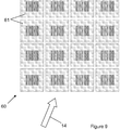
- FIG. 9 depicts another embodiment of the present invention.
- the spectrometer consists in a plurality of spectrometers 61, disposed in a 2D-matrix 60.
- Each spectrometer 61 comprises at least a grating and a detector, the grating being of any above-mentioned type (step, blazed or doubly-blazed) and being tunable or not.
- Each grating has a different distance d .
- the input collimated light 14 is projected simultaneously onto each spectrometer 61 of the 2D-matrix 60, respecting the configuration described on figure 1 .
- the detector of each spectrometer 61 (not represented on the figure) measures the intensity of the narrow band of wavelength produced by each grating. Thanks to the orientation described in figure 1 , the detectors can easily be disposed in such a way that it collects only the narrow band of wavelength produced by its corresponding grating without preventing the measurement of the other narrow bands of wavelength produced by the other gratings.
- the spectrum is measured in parallel, reducing the time required to get the entire spectrum. If the grating of each spectrometer 61 is not tunable, the whole spectrum is measured simultaneously, each spectrometer 61 measuring a given wavelength. The resolution of such a spectrometer is limited to the number of spectrometers 61 in the matrix 60.
- each spectrometer 61 measures a set of wavelength.
- the measurement of the spectrum is both sequential and parallel, reducing the measurement time but giving a good resolution.
- the mirrors used to project again the light onto a grating could also be concave in order to re-collimate the light before diffracting it again.
Landscapes
- Physics & Mathematics (AREA)
- Spectroscopy & Molecular Physics (AREA)
- General Physics & Mathematics (AREA)
- Optics & Photonics (AREA)
- Spectrometry And Color Measurement (AREA)
Claims (4)
- Monochromateur comprenant :- une ouverture d'entrée,- un collimateur, produisant, depuis une source de lumière (11), une lumière d'entrée collimatée (14),- un premier réseau (30) prévu pour diffracter ladite lumière d'entrée collimatée (14) et comprenant une pluralité de barreaux allongés (32) placés sur un substrat (31), lesdits barreaux allongés (32) étant placés parallèlement les uns aux autres le long d'un axe x, l'axe longitudinal de chacun desdits barreaux étant perpendiculaire à l'axe x, et les distances d1 entre deux barreaux consécutifs dans la direction de x étant égales et réglables, la partie supérieure de chaque barreau (32) comprenant, sur un premier côté longitudinal, une première surface plane réfléchissante inclinée (32a), et, sur un second côté longitudinal, une seconde surface plane réfléchissante inclinée (32b),- un premier miroir (41) et un second miroir (42),- une ouverture de sortie, etcaractérisé en ce que ladite lumière d'entrée collimatée (14) est prévue pour être parallèle à un plan P1, ledit plan P1 étant orienté de façon longitudinale par rapport auxdits barreaux (32) et de façon perpendiculaire par rapport aux premières surfaces planes réfléchissantes inclinées (32a), ladite lumière d'entrée collimatée (14) étant projetée sur ladite première surface inclinée (32a) à un angle a par rapport à la normale N de ladite première surface réfléchissante inclinée, et étant diffractée par le dit premier réseau (30) selon une première bande de longueur d'onde étroite collimatée,
et en ce que ledit premier miroir (41) et ledit second miroir (42) sont prévus de sorte que ladite première bande de longueur d'onde étroite collimatée soit parallèle à un plan P2 après réflexion sur le premier miroir (41) et sur le second miroir (42), ledit plan P2 étant orienté de façon longitudinale par rapport à l'axe longitudinal desdits barreaux (32), et de façon perpendiculaire par rapport aux secondes surfaces planes réfléchissantes inclinées (32b), ladite première bande de longueur d'onde étroite collimatée étant projetée sur ladite seconde surface inclinée (32b) à un angle a par rapport à la normale N de ladite seconde surface réfléchissante inclinée (32b), et étant diffractée par ledit premier réseau (30) selon une seconde bande de longueur d'onde étroite collimatée. - Monochromateur selon la revendication 1, caractérisé en ce que ledit monochromateur comprend en outre un troisième miroir (43), ledit troisième miroir (43) réfléchissant la seconde bande de longueur d'onde étroite collimatée, la normale dudit troisième miroir (43) étant parallèle à ladite seconde bande de longueur d'onde étroite collimatée.
- Spectromètre comprenant un monochromateur selon l'une quelconque des revendications précédentes, et un détecteur prévu pour mesurer l'intensité de la bande de longueur d'onde étroite collimatée produite par le monochromateur.
- Spectromètre de la revendication 3, caractérisé en ce que ledit spectromètre comprend en outre :- une pluralité de réseaux, lesdits réseaux étant prévus sous forme d'une matrice en 2D,
et- une pluralité de détecteurs, chacun étant prévu pour mesurer l'intensité de la bande de longueur d'onde étroite collimatée produite par l'un desdits réseaux.
Priority Applications (3)
| Application Number | Priority Date | Filing Date | Title |
|---|---|---|---|
| EP09151155.0A EP2211154B1 (fr) | 2009-01-22 | 2009-01-22 | Monochromateur à réseau accordable |
| US13/145,239 US8786853B2 (en) | 2009-01-22 | 2010-01-22 | Monochromator having a tunable grating |
| PCT/EP2010/050729 WO2010084174A2 (fr) | 2009-01-22 | 2010-01-22 | Spectromètre |
Applications Claiming Priority (1)
| Application Number | Priority Date | Filing Date | Title |
|---|---|---|---|
| EP09151155.0A EP2211154B1 (fr) | 2009-01-22 | 2009-01-22 | Monochromateur à réseau accordable |
Publications (2)
| Publication Number | Publication Date |
|---|---|
| EP2211154A1 EP2211154A1 (fr) | 2010-07-28 |
| EP2211154B1 true EP2211154B1 (fr) | 2017-03-15 |
Family
ID=40651353
Family Applications (1)
| Application Number | Title | Priority Date | Filing Date |
|---|---|---|---|
| EP09151155.0A Not-in-force EP2211154B1 (fr) | 2009-01-22 | 2009-01-22 | Monochromateur à réseau accordable |
Country Status (3)
| Country | Link |
|---|---|
| US (1) | US8786853B2 (fr) |
| EP (1) | EP2211154B1 (fr) |
| WO (1) | WO2010084174A2 (fr) |
Families Citing this family (2)
| Publication number | Priority date | Publication date | Assignee | Title |
|---|---|---|---|---|
| DE102015109340A1 (de) * | 2015-06-11 | 2016-12-15 | Sick Ag | Spektrometer und Analysevorrichtung |
| CN109211404A (zh) * | 2018-11-13 | 2019-01-15 | 徐州诺派激光技术有限公司 | 光纤光栅测试系统及光纤光栅性能测试方法 |
Family Cites Families (19)
| Publication number | Priority date | Publication date | Assignee | Title |
|---|---|---|---|---|
| US3775010A (en) | 1972-02-29 | 1973-11-27 | Cary Instruments | Assymmetric double pass grating monochromator |
| CA1229897A (fr) * | 1984-12-03 | 1987-12-01 | Gilbert M. Levy | Systeme optique spectrometre d'emission |
| JPH08145795A (ja) * | 1994-11-21 | 1996-06-07 | Anritsu Corp | 複単色計 |
| US5596407A (en) * | 1995-06-07 | 1997-01-21 | Varian Associates, Inc | Optical detector for echelle spectrometer |
| US5905571A (en) | 1995-08-30 | 1999-05-18 | Sandia Corporation | Optical apparatus for forming correlation spectrometers and optical processors |
| DE19708462A1 (de) * | 1997-02-17 | 1998-08-27 | Lla Umwelttechnische Analytik | Verfahren und Vorrichtung zur zeitaufgelösten optischen Spektralanalyse von laserinduzierten Mikroplasmen |
| JP2001304963A (ja) * | 2000-04-21 | 2001-10-31 | Ando Electric Co Ltd | 4段式分光器 |
| US6643065B1 (en) * | 2001-01-18 | 2003-11-04 | Donn Michael Silberman | Variable spacing diffraction grating |
| US6661513B1 (en) * | 2001-11-21 | 2003-12-09 | Roygbiv, Llc | Refractive-diffractive spectrometer |
| JP2003222556A (ja) * | 2002-01-31 | 2003-08-08 | Ando Electric Co Ltd | マルチパスモノクロメータ |
| US7027688B2 (en) * | 2002-05-14 | 2006-04-11 | Wildnauer Kenneth R | Tunable optical filter based on a physically-deformable diffractive element |
| DE102004028001A1 (de) * | 2004-06-09 | 2006-01-05 | Gesellschaft zur Förderung angewandter Optik, Optoelektronik, Quantenelektronik und Spektroskopie e.V. | Echelle-Spektrometer mit verbesserter Detektorausnutzung |
| US7342659B2 (en) * | 2005-01-21 | 2008-03-11 | Carl Zeiss Meditec, Inc. | Cross-dispersed spectrometer in a spectral domain optical coherence tomography system |
| US7458691B2 (en) * | 2005-06-09 | 2008-12-02 | Texas Instruments Incorporated | Holographic combiners for illumination of spatial light modulators in projection systems |
| US20070019194A1 (en) * | 2005-07-21 | 2007-01-25 | Liangyao Chen | Full spectral range spectrometer |
| EP1994433B1 (fr) | 2006-01-21 | 2009-07-08 | CSEM Centre Suisse d'Electronique et de Microtechnique SA Recherche et Développement | Laser sans saut de mode comportant un réseau blazé microfabriqué |
| WO2007089770A2 (fr) | 2006-01-31 | 2007-08-09 | Polychromix Corporation | Appareil et procédé de production d'un spectromètre à main |
| DE102006017705B4 (de) * | 2006-04-15 | 2010-01-07 | Carl Zeiss Microimaging Gmbh | Spektralanalytische Einheit mit einem Beugungsgitter und Laserscanning-Mikroskop |
| US20080309936A1 (en) * | 2007-06-18 | 2008-12-18 | Oxford Instruments Analytical Oy | Spectrometer with multiple gratings |
-
2009
- 2009-01-22 EP EP09151155.0A patent/EP2211154B1/fr not_active Not-in-force
-
2010
- 2010-01-22 US US13/145,239 patent/US8786853B2/en not_active Expired - Fee Related
- 2010-01-22 WO PCT/EP2010/050729 patent/WO2010084174A2/fr not_active Ceased
Non-Patent Citations (1)
| Title |
|---|
| None * |
Also Published As
| Publication number | Publication date |
|---|---|
| WO2010084174A3 (fr) | 2010-09-16 |
| US20110299078A1 (en) | 2011-12-08 |
| EP2211154A1 (fr) | 2010-07-28 |
| WO2010084174A2 (fr) | 2010-07-29 |
| US8786853B2 (en) | 2014-07-22 |
Similar Documents
| Publication | Publication Date | Title |
|---|---|---|
| US11307096B2 (en) | Spectral resolution enhancement device | |
| JP5517621B2 (ja) | 高感度スペクトル分析ユニット | |
| US8873048B2 (en) | Spectrometer arrangement | |
| US20210123809A1 (en) | Optical Interference Device | |
| US9207122B2 (en) | Fourier-transform interferometer with staircase reflective element | |
| JPH0339572B2 (fr) | ||
| US9638635B2 (en) | Spectrometer for analysing the spectrum of a light beam | |
| EP2724129B1 (fr) | Spectrographe à dilatation anamorphique des faisceaux | |
| US20100014082A1 (en) | Angle limiting reflector and optical dispersive device including the same | |
| EP3788329B1 (fr) | Spectromètre à haute résolution et à haut rendement | |
| WO2014159544A1 (fr) | Spectroscopie hadamard basée sur des mems à haute résolution | |
| US20010052980A1 (en) | Spectroscope for measuring spectral distribution | |
| US9638577B2 (en) | Spectrometer comprising a plurality of diffraction gratings | |
| CN101802572B (zh) | 光谱计装置 | |
| EP2211154B1 (fr) | Monochromateur à réseau accordable | |
| JP2009121986A (ja) | 分光装置 | |
| CN110501074B (zh) | 高通量宽谱段高分辨率的相干色散光谱成像方法及装置 | |
| CN110926613A (zh) | 一种消慧差宽带高分辨光谱仪 | |
| JP4009818B2 (ja) | 分光器及びそれを用いた光スペクトラムアナライザ | |
| CN209513049U (zh) | 光谱仪色散组件及光谱仪 | |
| US6583874B1 (en) | Spectrometer with holographic and echelle gratings | |
| KR102255340B1 (ko) | 역반사 표면을 갖는 분광기 및 관련 기구 | |
| JP2001116618A (ja) | 分光計 | |
| US20040145810A1 (en) | Method and apparatus for realizing an optical filter with an arbitrary narrow band impulse response | |
| JP2001264169A (ja) | 分光装置 |
Legal Events
| Date | Code | Title | Description |
|---|---|---|---|
| PUAI | Public reference made under article 153(3) epc to a published international application that has entered the european phase |
Free format text: ORIGINAL CODE: 0009012 |
|
| AK | Designated contracting states |
Kind code of ref document: A1 Designated state(s): AT BE BG CH CY CZ DE DK EE ES FI FR GB GR HR HU IE IS IT LI LT LU LV MC MK MT NL NO PL PT RO SE SI SK TR |
|
| AX | Request for extension of the european patent |
Extension state: AL BA RS |
|
| 17P | Request for examination filed |
Effective date: 20110128 |
|
| AKX | Designation fees paid |
Designated state(s): AT BE BG CH CY CZ DE DK EE ES FI FR GB GR HR HU IE IS IT LI LT LU LV MC MK MT NL NO PL PT RO SE SI SK TR |
|
| 17Q | First examination report despatched |
Effective date: 20110527 |
|
| GRAP | Despatch of communication of intention to grant a patent |
Free format text: ORIGINAL CODE: EPIDOSNIGR1 |
|
| INTG | Intention to grant announced |
Effective date: 20160818 |
|
| GRAS | Grant fee paid |
Free format text: ORIGINAL CODE: EPIDOSNIGR3 |
|
| GRAA | (expected) grant |
Free format text: ORIGINAL CODE: 0009210 |
|
| AK | Designated contracting states |
Kind code of ref document: B1 Designated state(s): AT BE BG CH CY CZ DE DK EE ES FI FR GB GR HR HU IE IS IT LI LT LU LV MC MK MT NL NO PL PT RO SE SI SK TR |
|
| REG | Reference to a national code |
Ref country code: CH Ref legal event code: EP Ref country code: GB Ref legal event code: FG4D |
|
| REG | Reference to a national code |
Ref country code: CH Ref legal event code: NV Representative=s name: NOVAGRAAF INTERNATIONAL SA, CH |
|
| REG | Reference to a national code |
Ref country code: IE Ref legal event code: FG4D |
|
| REG | Reference to a national code |
Ref country code: AT Ref legal event code: REF Ref document number: 876058 Country of ref document: AT Kind code of ref document: T Effective date: 20170415 |
|
| REG | Reference to a national code |
Ref country code: DE Ref legal event code: R096 Ref document number: 602009044714 Country of ref document: DE |
|
| REG | Reference to a national code |
Ref country code: NL Ref legal event code: MP Effective date: 20170315 |
|
| REG | Reference to a national code |
Ref country code: LT Ref legal event code: MG4D |
|
| PG25 | Lapsed in a contracting state [announced via postgrant information from national office to epo] |
Ref country code: NO Free format text: LAPSE BECAUSE OF FAILURE TO SUBMIT A TRANSLATION OF THE DESCRIPTION OR TO PAY THE FEE WITHIN THE PRESCRIBED TIME-LIMIT Effective date: 20170615 Ref country code: FI Free format text: LAPSE BECAUSE OF FAILURE TO SUBMIT A TRANSLATION OF THE DESCRIPTION OR TO PAY THE FEE WITHIN THE PRESCRIBED TIME-LIMIT Effective date: 20170315 Ref country code: GR Free format text: LAPSE BECAUSE OF FAILURE TO SUBMIT A TRANSLATION OF THE DESCRIPTION OR TO PAY THE FEE WITHIN THE PRESCRIBED TIME-LIMIT Effective date: 20170616 Ref country code: HR Free format text: LAPSE BECAUSE OF FAILURE TO SUBMIT A TRANSLATION OF THE DESCRIPTION OR TO PAY THE FEE WITHIN THE PRESCRIBED TIME-LIMIT Effective date: 20170315 Ref country code: LT Free format text: LAPSE BECAUSE OF FAILURE TO SUBMIT A TRANSLATION OF THE DESCRIPTION OR TO PAY THE FEE WITHIN THE PRESCRIBED TIME-LIMIT Effective date: 20170315 |
|
| REG | Reference to a national code |
Ref country code: AT Ref legal event code: MK05 Ref document number: 876058 Country of ref document: AT Kind code of ref document: T Effective date: 20170315 |
|
| PG25 | Lapsed in a contracting state [announced via postgrant information from national office to epo] |
Ref country code: SE Free format text: LAPSE BECAUSE OF FAILURE TO SUBMIT A TRANSLATION OF THE DESCRIPTION OR TO PAY THE FEE WITHIN THE PRESCRIBED TIME-LIMIT Effective date: 20170315 Ref country code: BG Free format text: LAPSE BECAUSE OF FAILURE TO SUBMIT A TRANSLATION OF THE DESCRIPTION OR TO PAY THE FEE WITHIN THE PRESCRIBED TIME-LIMIT Effective date: 20170615 Ref country code: LV Free format text: LAPSE BECAUSE OF FAILURE TO SUBMIT A TRANSLATION OF THE DESCRIPTION OR TO PAY THE FEE WITHIN THE PRESCRIBED TIME-LIMIT Effective date: 20170315 |
|
| PG25 | Lapsed in a contracting state [announced via postgrant information from national office to epo] |
Ref country code: NL Free format text: LAPSE BECAUSE OF FAILURE TO SUBMIT A TRANSLATION OF THE DESCRIPTION OR TO PAY THE FEE WITHIN THE PRESCRIBED TIME-LIMIT Effective date: 20170315 |
|
| PG25 | Lapsed in a contracting state [announced via postgrant information from national office to epo] |
Ref country code: EE Free format text: LAPSE BECAUSE OF FAILURE TO SUBMIT A TRANSLATION OF THE DESCRIPTION OR TO PAY THE FEE WITHIN THE PRESCRIBED TIME-LIMIT Effective date: 20170315 Ref country code: CZ Free format text: LAPSE BECAUSE OF FAILURE TO SUBMIT A TRANSLATION OF THE DESCRIPTION OR TO PAY THE FEE WITHIN THE PRESCRIBED TIME-LIMIT Effective date: 20170315 Ref country code: AT Free format text: LAPSE BECAUSE OF FAILURE TO SUBMIT A TRANSLATION OF THE DESCRIPTION OR TO PAY THE FEE WITHIN THE PRESCRIBED TIME-LIMIT Effective date: 20170315 Ref country code: SK Free format text: LAPSE BECAUSE OF FAILURE TO SUBMIT A TRANSLATION OF THE DESCRIPTION OR TO PAY THE FEE WITHIN THE PRESCRIBED TIME-LIMIT Effective date: 20170315 Ref country code: RO Free format text: LAPSE BECAUSE OF FAILURE TO SUBMIT A TRANSLATION OF THE DESCRIPTION OR TO PAY THE FEE WITHIN THE PRESCRIBED TIME-LIMIT Effective date: 20170315 Ref country code: ES Free format text: LAPSE BECAUSE OF FAILURE TO SUBMIT A TRANSLATION OF THE DESCRIPTION OR TO PAY THE FEE WITHIN THE PRESCRIBED TIME-LIMIT Effective date: 20170315 |
|
| PG25 | Lapsed in a contracting state [announced via postgrant information from national office to epo] |
Ref country code: IS Free format text: LAPSE BECAUSE OF FAILURE TO SUBMIT A TRANSLATION OF THE DESCRIPTION OR TO PAY THE FEE WITHIN THE PRESCRIBED TIME-LIMIT Effective date: 20170715 Ref country code: PL Free format text: LAPSE BECAUSE OF FAILURE TO SUBMIT A TRANSLATION OF THE DESCRIPTION OR TO PAY THE FEE WITHIN THE PRESCRIBED TIME-LIMIT Effective date: 20170315 Ref country code: PT Free format text: LAPSE BECAUSE OF FAILURE TO SUBMIT A TRANSLATION OF THE DESCRIPTION OR TO PAY THE FEE WITHIN THE PRESCRIBED TIME-LIMIT Effective date: 20170717 |
|
| REG | Reference to a national code |
Ref country code: DE Ref legal event code: R097 Ref document number: 602009044714 Country of ref document: DE |
|
| PLBE | No opposition filed within time limit |
Free format text: ORIGINAL CODE: 0009261 |
|
| STAA | Information on the status of an ep patent application or granted ep patent |
Free format text: STATUS: NO OPPOSITION FILED WITHIN TIME LIMIT |
|
| REG | Reference to a national code |
Ref country code: FR Ref legal event code: PLFP Year of fee payment: 10 |
|
| PG25 | Lapsed in a contracting state [announced via postgrant information from national office to epo] |
Ref country code: DK Free format text: LAPSE BECAUSE OF FAILURE TO SUBMIT A TRANSLATION OF THE DESCRIPTION OR TO PAY THE FEE WITHIN THE PRESCRIBED TIME-LIMIT Effective date: 20170315 |
|
| 26N | No opposition filed |
Effective date: 20171218 |
|
| PG25 | Lapsed in a contracting state [announced via postgrant information from national office to epo] |
Ref country code: SI Free format text: LAPSE BECAUSE OF FAILURE TO SUBMIT A TRANSLATION OF THE DESCRIPTION OR TO PAY THE FEE WITHIN THE PRESCRIBED TIME-LIMIT Effective date: 20170315 Ref country code: IT Free format text: LAPSE BECAUSE OF FAILURE TO SUBMIT A TRANSLATION OF THE DESCRIPTION OR TO PAY THE FEE WITHIN THE PRESCRIBED TIME-LIMIT Effective date: 20170315 |
|
| PG25 | Lapsed in a contracting state [announced via postgrant information from national office to epo] |
Ref country code: LU Free format text: LAPSE BECAUSE OF NON-PAYMENT OF DUE FEES Effective date: 20180122 |
|
| REG | Reference to a national code |
Ref country code: IE Ref legal event code: MM4A |
|
| REG | Reference to a national code |
Ref country code: BE Ref legal event code: MM Effective date: 20180131 |
|
| PG25 | Lapsed in a contracting state [announced via postgrant information from national office to epo] |
Ref country code: BE Free format text: LAPSE BECAUSE OF NON-PAYMENT OF DUE FEES Effective date: 20180131 |
|
| PG25 | Lapsed in a contracting state [announced via postgrant information from national office to epo] |
Ref country code: IE Free format text: LAPSE BECAUSE OF NON-PAYMENT OF DUE FEES Effective date: 20180122 |
|
| PGFP | Annual fee paid to national office [announced via postgrant information from national office to epo] |
Ref country code: CH Payment date: 20190130 Year of fee payment: 11 Ref country code: GB Payment date: 20190130 Year of fee payment: 11 Ref country code: FR Payment date: 20190130 Year of fee payment: 11 Ref country code: DE Payment date: 20190130 Year of fee payment: 11 |
|
| PG25 | Lapsed in a contracting state [announced via postgrant information from national office to epo] |
Ref country code: MC Free format text: LAPSE BECAUSE OF FAILURE TO SUBMIT A TRANSLATION OF THE DESCRIPTION OR TO PAY THE FEE WITHIN THE PRESCRIBED TIME-LIMIT Effective date: 20170315 |
|
| PG25 | Lapsed in a contracting state [announced via postgrant information from national office to epo] |
Ref country code: MT Free format text: LAPSE BECAUSE OF NON-PAYMENT OF DUE FEES Effective date: 20180122 |
|
| PG25 | Lapsed in a contracting state [announced via postgrant information from national office to epo] |
Ref country code: TR Free format text: LAPSE BECAUSE OF FAILURE TO SUBMIT A TRANSLATION OF THE DESCRIPTION OR TO PAY THE FEE WITHIN THE PRESCRIBED TIME-LIMIT Effective date: 20170315 |
|
| PG25 | Lapsed in a contracting state [announced via postgrant information from national office to epo] |
Ref country code: HU Free format text: LAPSE BECAUSE OF FAILURE TO SUBMIT A TRANSLATION OF THE DESCRIPTION OR TO PAY THE FEE WITHIN THE PRESCRIBED TIME-LIMIT; INVALID AB INITIO Effective date: 20090122 |
|
| PG25 | Lapsed in a contracting state [announced via postgrant information from national office to epo] |
Ref country code: MK Free format text: LAPSE BECAUSE OF NON-PAYMENT OF DUE FEES Effective date: 20170315 Ref country code: CY Free format text: LAPSE BECAUSE OF FAILURE TO SUBMIT A TRANSLATION OF THE DESCRIPTION OR TO PAY THE FEE WITHIN THE PRESCRIBED TIME-LIMIT Effective date: 20170315 |
|
| REG | Reference to a national code |
Ref country code: DE Ref legal event code: R119 Ref document number: 602009044714 Country of ref document: DE |
|
| REG | Reference to a national code |
Ref country code: CH Ref legal event code: PL |
|
| GBPC | Gb: european patent ceased through non-payment of renewal fee |
Effective date: 20200122 |
|
| PG25 | Lapsed in a contracting state [announced via postgrant information from national office to epo] |
Ref country code: GB Free format text: LAPSE BECAUSE OF NON-PAYMENT OF DUE FEES Effective date: 20200122 Ref country code: FR Free format text: LAPSE BECAUSE OF NON-PAYMENT OF DUE FEES Effective date: 20200131 Ref country code: DE Free format text: LAPSE BECAUSE OF NON-PAYMENT OF DUE FEES Effective date: 20200801 |
|
| PG25 | Lapsed in a contracting state [announced via postgrant information from national office to epo] |
Ref country code: CH Free format text: LAPSE BECAUSE OF NON-PAYMENT OF DUE FEES Effective date: 20200131 Ref country code: LI Free format text: LAPSE BECAUSE OF NON-PAYMENT OF DUE FEES Effective date: 20200131 |