EP2211363A2 - Verfahren zur Herstellung eines luftdichten Behälters und Bildanzeigevorrichtung - Google Patents
Verfahren zur Herstellung eines luftdichten Behälters und Bildanzeigevorrichtung Download PDFInfo
- Publication number
- EP2211363A2 EP2211363A2 EP10151276A EP10151276A EP2211363A2 EP 2211363 A2 EP2211363 A2 EP 2211363A2 EP 10151276 A EP10151276 A EP 10151276A EP 10151276 A EP10151276 A EP 10151276A EP 2211363 A2 EP2211363 A2 EP 2211363A2
- Authority
- EP
- European Patent Office
- Prior art keywords
- sealant
- container
- hole
- plate member
- cover member
- Prior art date
- Legal status (The legal status is an assumption and is not a legal conclusion. Google has not performed a legal analysis and makes no representation as to the accuracy of the status listed.)
- Granted
Links
- 238000004519 manufacturing process Methods 0.000 title claims abstract description 41
- 239000000565 sealant Substances 0.000 claims abstract description 179
- 125000006850 spacer group Chemical group 0.000 claims abstract description 72
- 238000007789 sealing Methods 0.000 claims abstract description 40
- 238000003825 pressing Methods 0.000 claims abstract description 20
- 238000010438 heat treatment Methods 0.000 claims description 12
- 239000004020 conductor Substances 0.000 claims description 4
- 238000000034 method Methods 0.000 abstract description 65
- 230000008569 process Effects 0.000 description 52
- 230000007246 mechanism Effects 0.000 description 21
- 239000011521 glass Substances 0.000 description 11
- 238000002844 melting Methods 0.000 description 10
- 230000008018 melting Effects 0.000 description 9
- 230000000694 effects Effects 0.000 description 8
- 239000000463 material Substances 0.000 description 5
- 229910001030 Iron–nickel alloy Inorganic materials 0.000 description 4
- 229910045601 alloy Inorganic materials 0.000 description 4
- 239000000956 alloy Substances 0.000 description 4
- 229910052738 indium Inorganic materials 0.000 description 4
- 229910052751 metal Inorganic materials 0.000 description 4
- 239000002184 metal Substances 0.000 description 4
- 229910000838 Al alloy Inorganic materials 0.000 description 3
- 230000003247 decreasing effect Effects 0.000 description 3
- 239000005361 soda-lime glass Substances 0.000 description 3
- 239000000758 substrate Substances 0.000 description 3
- 230000002950 deficient Effects 0.000 description 2
- 238000003303 reheating Methods 0.000 description 2
- 230000004044 response Effects 0.000 description 2
- 238000001179 sorption measurement Methods 0.000 description 2
- 229920002449 FKM Polymers 0.000 description 1
- 229910000846 In alloy Inorganic materials 0.000 description 1
- 229910001128 Sn alloy Inorganic materials 0.000 description 1
- 229910000831 Steel Inorganic materials 0.000 description 1
- 239000000853 adhesive Substances 0.000 description 1
- 230000001070 adhesive effect Effects 0.000 description 1
- 230000008859 change Effects 0.000 description 1
- 230000006378 damage Effects 0.000 description 1
- 230000003028 elevating effect Effects 0.000 description 1
- 230000006872 improvement Effects 0.000 description 1
- APFVFJFRJDLVQX-UHFFFAOYSA-N indium atom Chemical compound [In] APFVFJFRJDLVQX-UHFFFAOYSA-N 0.000 description 1
- 238000010030 laminating Methods 0.000 description 1
- 230000004048 modification Effects 0.000 description 1
- 238000012986 modification Methods 0.000 description 1
- 230000002093 peripheral effect Effects 0.000 description 1
- 230000000452 restraining effect Effects 0.000 description 1
- 238000004904 shortening Methods 0.000 description 1
- 229910052709 silver Inorganic materials 0.000 description 1
- 239000010959 steel Substances 0.000 description 1
- 230000003746 surface roughness Effects 0.000 description 1
- 238000004381 surface treatment Methods 0.000 description 1
- 238000004506 ultrasonic cleaning Methods 0.000 description 1
Images




Classifications
-
- H—ELECTRICITY
- H01—ELECTRIC ELEMENTS
- H01J—ELECTRIC DISCHARGE TUBES OR DISCHARGE LAMPS
- H01J9/00—Apparatus or processes specially adapted for the manufacture, installation, removal, maintenance of electric discharge tubes, discharge lamps, or parts thereof; Recovery of material from discharge tubes or lamps
- H01J9/40—Closing vessels
-
- H—ELECTRICITY
- H01—ELECTRIC ELEMENTS
- H01J—ELECTRIC DISCHARGE TUBES OR DISCHARGE LAMPS
- H01J29/00—Details of cathode-ray tubes or of electron-beam tubes of the types covered by group H01J31/00
- H01J29/86—Vessels; Containers; Vacuum locks
-
- H—ELECTRICITY
- H01—ELECTRIC ELEMENTS
- H01J—ELECTRIC DISCHARGE TUBES OR DISCHARGE LAMPS
- H01J9/00—Apparatus or processes specially adapted for the manufacture, installation, removal, maintenance of electric discharge tubes, discharge lamps, or parts thereof; Recovery of material from discharge tubes or lamps
- H01J9/24—Manufacture or joining of vessels, leading-in conductors or bases
- H01J9/26—Sealing together parts of vessels
- H01J9/261—Sealing together parts of vessels the vessel being for a flat panel display
-
- H—ELECTRICITY
- H01—ELECTRIC ELEMENTS
- H01J—ELECTRIC DISCHARGE TUBES OR DISCHARGE LAMPS
- H01J2209/00—Apparatus and processes for manufacture of discharge tubes
- H01J2209/26—Sealing parts of the vessel to provide a vacuum enclosure
-
- Y—GENERAL TAGGING OF NEW TECHNOLOGICAL DEVELOPMENTS; GENERAL TAGGING OF CROSS-SECTIONAL TECHNOLOGIES SPANNING OVER SEVERAL SECTIONS OF THE IPC; TECHNICAL SUBJECTS COVERED BY FORMER USPC CROSS-REFERENCE ART COLLECTIONS [XRACs] AND DIGESTS
- Y10—TECHNICAL SUBJECTS COVERED BY FORMER USPC
- Y10T—TECHNICAL SUBJECTS COVERED BY FORMER US CLASSIFICATION
- Y10T29/00—Metal working
- Y10T29/49—Method of mechanical manufacture
- Y10T29/49002—Electrical device making
- Y10T29/49117—Conductor or circuit manufacturing
- Y10T29/49124—On flat or curved insulated base, e.g., printed circuit, etc.
- Y10T29/4913—Assembling to base an electrical component, e.g., capacitor, etc.
- Y10T29/49146—Assembling to base an electrical component, e.g., capacitor, etc. with encapsulating, e.g., potting, etc.
-
- Y—GENERAL TAGGING OF NEW TECHNOLOGICAL DEVELOPMENTS; GENERAL TAGGING OF CROSS-SECTIONAL TECHNOLOGIES SPANNING OVER SEVERAL SECTIONS OF THE IPC; TECHNICAL SUBJECTS COVERED BY FORMER USPC CROSS-REFERENCE ART COLLECTIONS [XRACs] AND DIGESTS
- Y10—TECHNICAL SUBJECTS COVERED BY FORMER USPC
- Y10T—TECHNICAL SUBJECTS COVERED BY FORMER US CLASSIFICATION
- Y10T29/00—Metal working
- Y10T29/49—Method of mechanical manufacture
- Y10T29/49002—Electrical device making
- Y10T29/49117—Conductor or circuit manufacturing
- Y10T29/49124—On flat or curved insulated base, e.g., printed circuit, etc.
- Y10T29/49147—Assembling terminal to base
-
- Y—GENERAL TAGGING OF NEW TECHNOLOGICAL DEVELOPMENTS; GENERAL TAGGING OF CROSS-SECTIONAL TECHNOLOGIES SPANNING OVER SEVERAL SECTIONS OF THE IPC; TECHNICAL SUBJECTS COVERED BY FORMER USPC CROSS-REFERENCE ART COLLECTIONS [XRACs] AND DIGESTS
- Y10—TECHNICAL SUBJECTS COVERED BY FORMER USPC
- Y10T—TECHNICAL SUBJECTS COVERED BY FORMER US CLASSIFICATION
- Y10T29/00—Metal working
- Y10T29/49—Method of mechanical manufacture
- Y10T29/49826—Assembling or joining
-
- Y—GENERAL TAGGING OF NEW TECHNOLOGICAL DEVELOPMENTS; GENERAL TAGGING OF CROSS-SECTIONAL TECHNOLOGIES SPANNING OVER SEVERAL SECTIONS OF THE IPC; TECHNICAL SUBJECTS COVERED BY FORMER USPC CROSS-REFERENCE ART COLLECTIONS [XRACs] AND DIGESTS
- Y10—TECHNICAL SUBJECTS COVERED BY FORMER USPC
- Y10T—TECHNICAL SUBJECTS COVERED BY FORMER US CLASSIFICATION
- Y10T29/00—Metal working
- Y10T29/49—Method of mechanical manufacture
- Y10T29/49826—Assembling or joining
- Y10T29/49908—Joining by deforming
- Y10T29/49915—Overedge assembling of seated part
Definitions
- the present invention relates to a manufacturing method of an airtight container.
- the present invention relates to a manufacturing method of a vacuum airtight container (envelope) used for a flat panel image displaying apparatus.
- An image displaying apparatus in which a number of electron-emitting devices for emitting electrons according to image signals are provided on a rear plate and a fluorescent film for displaying an image by emitting light in response to irradiation of electrons is provided on a face plate, and of which the inside is maintained with vacuum, has been known.
- the face plate and the rear plate are bonded to each other through a support frame, thereby forming an envelope.
- Such an exhausting process can be achieved by several kinds of methods. As one of these methods, a method of exhausting the inside of a container through a through-hole provided on the surface of the container and thereafter sealing the through-hole by a cover member has been known.
- Japanese Patent Application Laid-Open No. 2003-192399 discloses a technique for tapering the face of a cover member opposite to a through-hole. More specifically, in the patent document 1, the distance between the tapered face and the face on which the through-hole has been formed becomes wider as the tapered face goes apart from the periphery of the through-hole. Then, a melted sealant is deformed due to the weight of the sealant itself, and the deformed sealant moves toward the tapered portion, thereby restraining the sealant from flowing into the through-hole.
- United States Patent No. 6,261,145 discloses a technique for closing up a circular through-hole by a spherical metal cap or the like, externally filling up a sealant to the contact portion between the through-hole and the metal cap, and thus sealing the through-hole. More specifically, in the patent document 2, since the cap is fit into the tapered through-hole, the force toward the inside of a container is applied to the cap if the inside of the cap is vacuum. Thus, since the cap is in tightly contact with the through-hole easily, it becomes difficult for the sealant to flow into the through-hole.
- the present invention aims, in a manufacturing method of an airtight container including a process of sealing a through-hole by a cover member, to provide the manufacturing method which can secure sealing performance and also restrain a sealant from flowing into the through-hole. Moreover, the present invention aims to provide a manufacturing method of an image displaying apparatus, which uses the relevant manufacturing method of the airtight container.
- An airtight container manufacturing method in the present invention comprises: (a) exhausting an inside of a container through a through-hole provided on the container; (b) arranging a spacer member along a periphery of the through-hole on an outer surface of the container the inside of which has been exhausted; (c) arranging a plate member so that the spacer member and the through-hole are covered by the plate member and a gap is formed along a side surface of the spacer member between the plate member and the outer surface of the container; and (d) arranging a cover member so as to cover the plate member and bonding the arranged cover member and the outer surface of the container to each other via a sealant positioned between the cover member and the outer surface of the container, wherein the bonding includes hardening the sealant after deforming the sealant as pressing the plate member by the cover member so that the gap is infilled with the sealant.
- Another airtight container manufacturing method in the present invention comprises: (a) exhausting an inside of a container through a through-hole provided on the container, and preparing a laminated body in which a spacer member, a plate member and a cover member are laminated with a sealant interposed between the plate member and the cover member; and (b) pressing the laminated body toward the outer surface of the container the inside of which has been exhausted, so that the through-hole is covered by the plate member, and bonding the cover member and the outer surface of the container to each other via the sealant, wherein the bonding includes arranging the laminated body so that a gap is formed along a side surface of the spacer member between the plate member and the outer surface of the container, and the bonding further includes hardening the sealant after deforming the sealant as pressing the plate member by the cover member so that the gap is infilled with the sealant.
- a manufacturing method of an image displaying apparatus comprises manufacturing an envelope an inside of which has been vacuumized, by using the airtight container manufacturing methods described as above.
- the airtight container manufacturing method including sealing the through-hole by the cover member
- the airtight container manufacturing method which can efficiently secure the sealing performance and also restrain the sealant from flowing into the through-hole.
- the image displaying apparatus manufacturing method which uses the airtight container manufacturing method described as above.
- FIGS. 1A, 1B, 1C, 1D, 1E and 1F are schematic step views indicating a sealing process of the first embodiment.
- FIGS. 2A, 2B, 2C, 2D and 2E are schematic step views indicating a sealing process of the second embodiment.
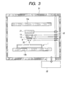
- FIG. 3 is a view indicating the first embodiment.
- FIG. 4 is a view indicating the second embodiment.
- FIGS. 5A, 5B, 5C, 5D and 5E are views indicating the third embodiment.
- FIG. 6 is a view indicating the third embodiment.
- FIG. 7 is a view indicating the fourth embodiment.
- a manufacturing method of an airtight container of the present invention can be widely applied to a manufacturing method of an airtight container of which the inside is exhausted to be vacuumized.
- the present invention can be preferably applied to a manufacturing method of an envelope of a flat panel image displaying apparatus of which the inside is exhausted to be vacuumized.
- FIGS. 1A to 1F are the schematic step views indicating a sealing process, which can be particularly preferably used in a case where a through-hole is sealed under a state that the through-hole of an airtight container is placed on the upper surface of an envelope.
- the container 1 can have desired materials and constitution. In case of a flat panel image displaying apparatus, a part of the container 1 is usually manufactured by glass.
- the container 1 is composed of a face plate 2, a rear plate 3 and a support frame 4, which are mutually bonded by a proper means such as a glass frit or the like, to form an airtight container.
- a large number of electron emitters (not illustrated) for emitting electrons in accordance with an image signal are provided on the rear plate 3.
- a fluorescent film (not illustrated), which emits light upon receiving irradiation of electrons and thus displays images, is provided on the face plate 2.
- the through-hole 5 which is an aperture nearly equal to a circular form, is provided on the rear plate 3.
- the position and the size of the through-hole 5 are properly set in consideration of a desired degree of vacuum in the container 1, a desired exhausting time, and the like.
- only one through-hole 5 is provided, however plural through-holes may be provided.
- a surface treatment may be performed to the circumference portion of the through-hole 5 on an outer surface 6 of the container 1 by use of an ultrasonic cleaning process, or a metal film may be deposited.
- An exhaust unit of the container 1 is selected so that the inside of the container 1 becomes a desired degree of vacuum.
- the exhaust unit is not especially limited if the inside of the container 1 can be exhausted by the exhaust unit via the through-hole 5 and thus a process to be described later can be performed.
- moving mechanisms rotating/vertical moving mechanisms 20 and 23 in the later-described examples
- later-described respective members a plate member 8, a cover member 13, a spacer member 32, etc.
- the spacer member 32 is arranged along a periphery 9 of the through-hole 5 on the outer surface 6 of the container 1, of which the inside S has been exhausted.
- the plate member 8 is arranged so that the spacer member 32 and the through-hole 5 are covered by the plate member 8 and a gap 14b is formed along the side surface of the spacer member 32 between the plate member 8 and the outer surface of the container 1. More specifically, the spacer member 32 is arranged so that the outer surface of the container 1 along the periphery of the through-hole 5 is in contact with the spacer member 32.
- the plate member 8 is arranged so that the spacer member 32 is interposed between the outer surface of the container 1 and the plate member 8 and the through-hole 5 is covered by the plate member 8.
- the plate member 8 of which the size is larger than that of the through-hole 5 is a circular member of which the diameter is larger than that of the through-hole 5, in the present embodiment.
- the spacer member 32 of which the plate area (i.e., the inner-side area of the periphery of the ring portion) is smaller than that of the plate member 8 is a ring-shaped member of which the outside diameter is smaller than that of the plate member 8 and of which the bore diameter is larger than the diameter of the through-hole 5, in the present embodiment.
- the plate member 8, the spacer member 32 and the through-hole 5 are almost concentrically arranged.
- a contact surface 10a between the plate member 8 and the spacer member 32 and a contact surface 10b between the spacer member 32 and the outer surface of the container 1 together prevent that the sealant 12 flows into the through-hole 5. Therefore, it is desirable that the configuration and surface roughness of each of the plate member 8, the spacer member 32 and the outer surface of the container 1 are defined so that gaps (leak paths) between the respective members at the contact surfaces 10a and 10b become tight.
- the thickness of the plate member 8 and the thickness of the spacer member 32 are properly defined in consideration of sealing performance and deformation characteristic of the sealant 12.
- the sealant 12 is provided on a surface 11 (refer to FIG. 1B ) of the plate member 8 opposite to the contact surface 10a between the plate member 8 and the spacer member 32.
- the sufficient amount of the sealant 12 is provided so that the sealant 12 covers the plate member 8 by protruding to the outside of the plate member 8 and the sealant 12 becomes thicker than the plate member 8.
- the material of the sealant 12 is not especially limited if it can obtain desired sealing performance and adhesive characteristic.
- a glass frit, or low-melting metal such as an In alloy, a Sn alloy or the like is used as the sealant 12 in consideration of high sealing performance or stress in heating.
- the cover member 13 is arranged on the sealant 12.
- the cover member 13 is arranged so as to cover the plate member 8.
- the sealant 12 is pressed in the vertical downward direction (direction indicated by an outline arrow) by the cover member 13 to deform the sealant 12.
- the sealant 12 is pressed by the cover member 13 so that the sealant 12 fills up a space 14a between the cover member 13 and the outer surface 6 of the container 1 and a space 14b between the plate member 8 and the outer surface 6 of the container 1 along an outer circumference portion 15a of the plate member 8 and an outer circumference portion 15b of the spacer member 32.
- the sealant 12 is deformed and thus moved to the space 14a so that a part of the sealant 12 wraps around the outer circumference portion 15a of the plate member 8. Further, if the sealant 12 is further pressed by the cover member 13, the sealant 12 is moved up to the space 14b.
- the spaces 14a and 14b are completely infilled with the sealant 12, and the width of the sealant 12 is extended to such a width nearly equal to that of the cover member 13. After that, the sealant 12 is heated, and then cooled down to be hardened.
- the sealant 12 is not always required to be deformed to become such the condition.
- the sealant 12 is not required to be extended to the same width as that of the cover member 13.
- the space 14a between the cover member 13 and the outer surface 6 of the container 1 and the space 14b between the plate member 8 and the outer surface 6 of the container 1 are not always required to be infilled with the sealant.
- the sealant 12 does not remain between the plate member 8 and the cover member 13 in FIG. 1F , a part of the sealant 12 may remain between the plate member 8 and the cover member 13.
- the heat from the plate member 8, the cover member 13 or the spacer member 32 is transmitted to the sealant 12, and a heating effect for the sealant 12 can be obtained. It is desirable that the heating temperature is set so that the plate member 8, the cover member 13 or the spacer member 32 is not destroyed by a sudden change of temperature.
- a method of applying the load can be properly selected.
- a means of using a spring, mechanically applying the press force or arranging a weight can be enumerated.
- the applying of the load to keep the position of the cover member 13 and the applying of the load to deform the sealant 12 are realized by the same load, different means may be used.
- a force of sufficiently squashing the sealant is required so that the sealant keeps at least airtightness.
- the sealant 12 When the sealant 12 is deformed, the sealant 12 may be pressed by the cover member 13 while rotating the cover member 13 around an axis parallel to the direction of pressing the sealant 12 (for example, a central axis C of the cover member 13) as a center of rotation as indicated in FIG. 1E .
- the sealant 12 is more effectively deformed, whereby the spaces 14a and 14b are uniformly infilled with the sealant 12.
- the sealant 12 is deformed while the plate member 8 is being pressed by the cover member 13, and then the sealant 12 is hardened, whereby sealing and bonding are completed. That is, when the sealant 12 is melted and deformed, the plate member 8 and the spacer member 32 close up the through-hole 5 while being pressed toward the through-hole 5. Therefore, the sealing performance at the contact surface 10a between the plate member 8 and the spacer member 32 and at the contact surface 10b between the spacer member 32 and the outer surface 6 of the container 1 is enhanced, whereby the melted sealant 12 becomes hard to flow into the through-hole 5.
- both the sealing effect at the space 14a between the outer surface 6 of the container 1 and the cover member 13 by the sealant 12 and the sealing effect at the space 14b between the plate member 8 and the outer surface 6 of the container 1 by the sealant 12 can be expected.
- the two sealing portions are arranged in series as described above, the sealing performance itself is improved, and also defective airtightness can be easily prevented.
- the total thickness of the plate member 8 and the spacer member 32 results to define the minimum value of the thickness of the sealant 12. Therefore, even if the pressing load is large in some degree, deformation of the sealant 12 is prevented to be fixed to such a level less than the total thickness of the plate member 8 and the spacer member 32, and this fact leads to an improvement of reliability of airtightness.
- the plate member 8, the cover member 13 and the spacer member 32 it is not desirable to increase the pressing load particularly.
- the sealant 12 is arranged on the back surface 11 of the plate member 8.
- a sealing process may be performed by applying the sealant 12 to the side of the plate member 8 little thicker while pressing (squashing) the sealant 12 and the plate member 8 by the cover member 13. That is, if the cover member 13 and the outer surface 6 of the container 1 are finally bonded to each other via the sealant 12 positioned at the space 14a and the plate member 8 and the outer surface 6 of the container 1 are finally bonded to each other via the sealant 12 positioned at the space 14b, the position of initially providing the sealant 12 can be properly determined.
- the present embodiment is different from the first embodiment in a point that the through-hole is sealed by bringing a laminated body composed of the spacer member, the plate member, the sealant and the cover member into contact with the through-hole from the downside of the through-hole, and other points in the present embodiment are the same as those in the first embodiment. Therefore, in the following description, the point different from the first embodiment will be mainly described. Namely, as to the matters not described in the following, the description in the first embodiment should be referred.
- FIGS. 2A to 2E are the schematic step views indicating a sealing process which can be especially preferably used in a case where the through-hole is sealed in a state that the through-hole of the airtight container was opened to the vertical downward direction.
- the inside of the container 1 is exhausted via the through-hole 5 provided on the surface of the container 1. This step is the same as that in the first embodiment.
- a laminated body 16, in which a plate member 8a and the cover member 13 are laminated with the sealant 12 interposed between the plate member 8a and the cover member 13, is prepared.
- the cover member 13 which is the same as that in the first embodiment, can be used.
- the plate member the plate member 8 in the first embodiment can be used.
- the plate member 8a which has a cylindrical or semispherical projection 18 capable of being inserted inside a through-hole 5a, is used.
- the spacer member 32 which has a ring shape, is laminated in the state that the projection 18 of the plate member 8a is being inserted in the spacer member 32.
- the projection 18 is inserted into the through-hole 5a. That is, the projection 18 functions as a guide when the plate member 8a is pressed to the through-hole 5a. Therefore, it is desirable that the projection 18 has such a size (diameter) to be naturally set in the through-hole 5a.
- the sealant 12 which is the same as that in the first embodiment, can be used.
- at least one of the plate member 8a and the cover member 13 may be heated within a range that the sealant 12 is not melted.
- the laminated body 16 is arranged on the outer surface 6 of the container 1 of which the inside has been exhausted so that the spacer member 32 is in contact with the outer surface 6 along the periphery 9 (refer to FIG. 2A ) of the through-hole 5a and the through-hole 5a is covered by the plate member 8a.
- the laminated body 16 is arranged so that the space 14b along the side surface of the spacer member 32 is formed between the plate member 8a and the outer surface 6 of the container 1.
- the above operation is performed in a state that the through-hole 5a is opened in the vertical downward direction, as described above. Since the projection 18 is inserted in the through-hole 5a and the spacer member 32, positioning is easily performed.
- the whole or a part of the laminated body 16 may be heated to the extent that the sealant 12 is not melted.
- the sealant 12 is pressed in the vertical upward direction (i.e., the direction indicated by the outline arrow) by the cover member 13.
- a means of applying load can be properly selected as well as the first embodiment. While maintaining this condition, the sealant 12 is heated to a temperature of melting the sealant 12. The melted sealant 12 is then deformed so that the space 14a between the cover member 13 and the outer surface 6 of the container 1 and the space 14b between the plate member 8a and the outer surface 6 of the container 1 are respectively infilled with the sealant 12 along an outer circumference portion 15a of the spacer member 32 and an outer circumference portion 15b of the plate member 8a. More specifically, when the sealant 12 is pressed by the cover member 13, as indicated in FIG.
- a part of the sealant 12 is moved to the lateral direction of the plate member 8a while the sealant 12 is being deformed. Further, another part of the sealant 12 is dragged by the cover member, and thus extended to the lateral direction.
- the sealant 12 is further pressed by the cover member 13, as indicated in FIG. 2E , the spaces 14a and 14b are completely infilled with the sealant 12, and the width of the sealant 12 is extended to such a width nearly equal to that of the cover member 13. Thereafter, the sealant 12 is heated, and then cooled down to be hardened.
- the laminated body is pressed so that the plate member closes up the through-hole, and the cover member and the outer surface of the container are bonded via the sealant, whereby the container 1 is sealed.
- the sealing process includes a process of hardening the sealant after deforming the sealant while pressing the plate member by the cover member is substantially the same as that in the first embodiment.
- the through-hole can be sealed in a state that the through-hole is opened in the vertical downward direction, and the same effect as that in the first embodiment can be achieved. That is, the melted sealant 12 hardly flows into the through-hole 5a.
- a discharge phenomenon caused by the sealant 12 flowing in the apparatus can be easily prevented.
- a negative influence to the electron emitter or the like due to gas hardly occurs.
- sealing performance itself is improved, and defective airtightness can be easily prevented. Even if the pressing load is large in some degree, it can be prevented that the sealant 12 is deformed to have a thickness equal to or less than the total thickness of the plate member 8a and the spacer member 32, thereby improving reliability of airtightness.
- a process of sequentially providing the spacer member 32, the plate member 8a, the sealant 12 and the cover member 13 is not required, and a process of forming the laminated body 16 can be individually performed. Therefore, also an effect capable of rationalizing the sealing process is obtained.
- the laminated body composed of the spacer member, the plate member, the sealant and the cover member is brought into contact with the airtight container from the downward side.
- the present invention is not limited to this. That is, the laminated body may be brought into contact with the airtight container from the upward side or the horizontal side according to a position of the through-hole.
- the laminated body may be brought into contact with the airtight container from the upward side or the horizontal side according to a position of the through-hole.
- the spacer member is provided independently of the plate member.
- the same effect can be obtained even if the spacer member and the plate member are integrated.
- working processes can be totally reduced.
- the container 1 was stored in a vacuum-exhaust chamber 31, and the vacuum-exhaust chamber 31 was then exhausted to be vacuumized by using an exhaust unit 22 containing a turbo molecular pump and a dry scroll pump. Further, heaters 19a and 19b used as heating units were provided in the vacuum-exhaust chamber 31, and the through-hole 5 having the diameter of 3mm was provided on the upper surface of the container 1.
- a soda lime glass having the diameter of 5mm and the thickness of 300 ⁇ m was prepared.
- sealant 12 a glass frit, which was molded to have the diameter of 7mm and the thickness of 400 ⁇ m by pre-baking and from which a paste component had been eliminated, was prepared.
- cover member 13 a soda lime glass having the diameter of 8mm and the thickness of 800 ⁇ m was prepared.
- spacer member 32 soda lime glass having the outside diameter of 4mm, the bore diameter of 3mm and the thickness of 800 ⁇ m was prepared.
- a load applying weight 21 a weight of 150g made by SUS340 (Steel Use Stainless 340) was prepared. After then, these members were mounted on the rotating/vertical moving mechanism 20 capable of individually performing vertical movement and rotational movement for each of the members, and the mounted members were arranged in the vacuum-exhaust chamber 31.
- the exhaust unit 22 was operated to exhaust the inside of the vacuum-exhaust chamber 31, and the vacuum degree of the inside of the container 1 was decreased to a level equal to or less than 1 ⁇ 10 -3 Pa via the through-hole 5.
- the heaters 19a and 19b were operated in correspondence with the exhausting process, and the respective members arranged inside the vacuum-exhaust chamber 31 were heated to 350°C which is equal to or less than a softening temperature of the glass frit serving as the sealant 12.
- the spacer member 32 and the plate member 8 were arranged immediately above the through-hole 5 by using the rotating/vertical moving mechanism 20.
- the sealant 12 was arranged immediately above the plate member 8 by using the rotating/vertical moving mechanism 20.
- the cover member 13 was arranged immediately above the sealant 12 by using the rotating/vertical moving mechanism 20. After then, the load applying weight 21 was rotationally moved to the position immediately above the cover member 13 by using the rotating/vertical moving mechanism 20. The load applying weight 21 was slowly descended at speed of 1mm/min by using the rotating/vertical moving mechanism 20 so that the load was not rapidly added, and then the load applying weight 21 was mounted on the cover member 13.
- the heating process was executed to reach a softening temperature of the glass frit.
- the load applying weight 21 was cooled to a room temperature while being mounted on the cover member 13, the inside of the vacuum-exhaust chamber 31 was then purged, and the manufactured container 1 was taken out from the vacuum-exhaust chamber 31.
- the vacuum airtight container of which the through-hole had been sealed by the sealant and the inside had been exhausted to be vacuumized was manufactured.
- the glass frit was formed closely in the space 14a between the cover member 13 and the outer surface 6 of the container 1 and in the space 14b between the plate member 8 and the outer surface 6 of the container 1.
- the plate member 8 and the spacer member 32 were continuously pressed toward the periphery of the through-hole 5 while the glass frit serving as the sealant was melted and squashed in the process (e) by the fact that the load applying weight 21 was mounted on the cover member 13 in the process (d). For this reason, a fact that the sealant 12 flowed into the through-hole 5 was not confirmed.
- the vacuum airtight container having sufficient airtightness could be obtained.
- the container 1 was stored in a vacuum-exhaust chamber 31, and the vacuum-exhaust chamber 31 was then exhausted to be vacuumized by using an exhaust unit 22 having a turbo-molecular pump and a dry scroll pump. Further, heaters 19a and 19b used as heating units were provided in the vacuum-exhaust chamber 31.
- the container 1 had two substrates oppositely arranged each other, and surface conduction electron-emitting devices (not illustrated) were formed on the inner surface of one substrate and an anode electrode and a light emission member (not illustrated) were formed on the inner surface of the other substrate. Further, the container 1 had the through-hole 5a having the diameter of 4mm, on its lower surface.
- non-alkaline glass having the diameter of 10mm and the thickness of 500 ⁇ m was prepared.
- the sealant 12 composed of In (indium) and molded to have the diameter of 8mm and the thickness of 400 ⁇ m was provided on the cover member 13.
- the plate member 8a of non-alkaline glass having the diameter of 5mm and the thickness of 300 ⁇ m and having at its center the projection 18 having the diameter of 1mm and the height of 2mm was mounted on the sealant 12, and the spacer member 32 of an aluminum alloy having the outside diameter of 4.8mm, the bore diameter of 4mm and the thickness of 50 ⁇ m was mounted on the plate member 8a, whereby the laminated body 16 was prepared.
- the rotating/vertical moving mechanism 23 was equipped with a stage 24 capable of applying pressing force to be operated in the vertical upward direction by a spring member 25 having the spring constant of about 1N/mm (100gf/mm).
- the laminated body 16 set on the stage 24 was arranged in the vacuum-exhaust chamber 31.
- the laminated body 16 was escaped to a position not to be heated by the heaters 19a and 19b, by using the rotating/vertical moving mechanism 23.
- the exhaust unit 22 was operated to exhaust the inside of the vacuum-exhaust chamber 31, and the vacuum degree of the inside of the container 1 was decreased to a level equal to or less than 1 ⁇ 10 -4 Pa via the through-hole 5a.
- the heaters 19a and 19b were operated in correspondence with the exhausting process, and the container 1 was heated at 350°C for an hour by the heaters 19a and 19b to exhaust adsorption gas in the container 1. After that, the heaters 19a and 19b and the container 1 were naturally cooled to reach the temperature of 100°C.
- the laminated body 16 was moved to the position immediately below the through-hole 5a by the rotating/vertical moving mechanism 23. Subsequently, a reheating process was performed by the heaters 19a and 19b while the inside of the vacuum-exhaust chamber 31 was being exhausted continuously.
- the container 1, the stage 24 including the spring member 25, and the laminated body 16 were respectively heated to 100°C being equal to or less than a melting temperature of In, so as to have the same temperature as that of the container 1.
- the laminated body 16 held by the stage 24 was slowly moved upward by using the rotating/vertical moving mechanism 23 until the spacer member 32 came into contact with the periphery of the through-hole 5a in a state of the projection 18 of the plate member 8a being inserted in the through-hole 5a. Subsequently, the rotating/vertical moving mechanism 23 was moved upward by 5mm at speed of 1mm/sec so that the plate member 8a was pressed by the spring member 25.
- the temperatures of the container 1 and the respective members were raised to 160°C, which is equal to or higher than the melting temperature of In, at a speed rate of 3°C/min by the heaters 19a and 19b. Also, when In was melted, since the respective members were being continuously pressed toward the through-hole 5a by the spring member 25, the sealant 12 was deformed according to melting of In, whereby the through-hole 5a was sealed.
- the temperature was cooled down to the room temperature while the laminated body 16 was being pressed by the spring member 25. Then, the inside of the vacuum-exhaust chamber 31 was purged, and the manufactured container 1 was taken out from the vacuum-exhaust chamber 31.
- an image forming apparatus of which the inside had been exhausted to be vacuumized, having therein surface conduction electron-emitting devices could be obtained.
- voltage of 15kV was applied between an anode electrode and a cathode electrode of the image forming apparatus for 24 hours, any electric discharge was not generated in an area of the image forming apparatus and its peripheral area, and it was confirmed that electron accelerating voltage could be stably applied.
- the container 1 had a through-hole having the diameter of 2mm on its lower surface, and had therein a support member (a spacer for withstand atmosphere pressure) 26 so as not to be destroyed even if the load was locally applied to the periphery of an aperture from the outside of the container.
- a flange 30 serving as an exhaust pipe and having the bore diameter larger than that of the through-hole had therein the rotating/vertical moving mechanism 23 according to a straight line manipulator, the spring member 25 and an internal heater 19c connected to the spring member. If the heater was pressed to the container side by the rotating/vertical moving mechanism, the load could be applied according to a pressing degree.
- the exhaust unit 22 having the turbo-molecular pump and the dry scroll pump was connected to the flange 30, so as to be able to exhaust the inside of the flange 30 to be vacuumized.
- the plate member 8a which had a projection having the diameter of 1.9mm and the height of 500 ⁇ m on a disc-like plate having the diameter of 5mm and the height of 500 ⁇ m, was formed by PD-200 available from Asahi Glass Co., Ltd.
- the sealant 12 was formed from an alloy of In and Ag molded to have the diameter of 5mm and the thickness of 1.45mm.
- a cover member 13a a tray-like member having a concave portion having the diameter of 7mm and the depth of 1mm was formed by PD-200.
- As the spacer member 32 a ring-like member having the outside diameter of 3mm, the bore diameter of 2mm and the thickness of 50 ⁇ m was formed by an aluminum alloy. Then, the spacer member 32, the plate member 8a, the sealant 12 and the cover member 13a were laminated mutually in this order to form the laminated body, and the formed laminated body was arranged within the exhaust pipe.
- the cover member 13a, the sealant 12, the plate member 8a and the spacer member 32 were sequentially laminated and arranged on the internal heater 19c arranged inside the flange 30 so that the centers of the respective diameters of these members were coincided with others.
- An O-ring 29 composed of a material Viton® (registered trademark) was arranged on the aperture of the flange 30.
- Vacuum exhaust was started by the exhaust unit 22 while the O-ring 29 was being pressed by the container 1 and the flange 30 at a position where the O-ring 29 was in contact with the periphery of the through-hole 5a of the container 1 and the centers of the diameters of the respective members in the process (a) coincided with the center of the through-hole 5a.
- the inside of the container 1 was exhausted to be vacuumized.
- the internal heater 19c in the flange 30 was heated up to 150°C and held, the temperature was raised to 170°C at a speed rate of 1°C/min. Subsequently, the laminated body composed of the spacer member 32, the plate member 8a, the sealant 12 and the cover member 13a was moved along the exhaust pipe by elevating the rotating/vertical moving mechanism in the flange at speed of 1mm/min, and the laminated body was pressed to the outer surface of the container while being arranged so as to close up through-hole.
- the internal heater 19c was naturally cooled to the room temperature while the state of applying the press force in the process (d) was kept. Then, after the sealant 12 was hardened, the exhausting process by the exhaust unit 22 was stopped, the inside of the flange 30 was purged by air, and then the O-ring 29 was separated from the container 1.
- the container was sealed by bonding the outer surface of the container to the cover member and bonding the outer surface of the container to the plate member respectively via the sealant, and the vacuum airtight container of which the inside had been exhausted to be vacuumized was manufactured.
- the process (d) since the plate member 8a and the spacer member 32 were continuously pressed toward the through-hole 5a while the sealant 12 was being melted and deformed, it was able to prevent the sealant 12 from flowing into the through-hole 5a.
- the vacuum airtight container having sufficient airtightness could be obtained.
- the tray shape of the cover member 13a was formed so as to hold the plate member 8a and the spacer member 32 in a state that the side wall of the tray shape was in contact with the outer surface 6 of the container 1, it was able to prevent the sealant 12 from overflowing outside the tray shape of the cover member.
- the capacity of the inside of the tray shape (i.e., the capacity of the concave portion) of the cover member 13a and the sum of the volume of the plate member 8a held inside the tray shape of the cover member 13a and the volume of the sealant were aligned. For this reason, the sealant was formed closely in the inside (i.e., the concave portion) of the cover member 13a, an appearance with the sealant not overflowing outside the cover member 13a was obtained.
- an anode electrode 28 was provided inside the container 1 serving as an envelope, and a spring terminal 27 serving as a terminal unit composed of a conductive material was provided on the plate member 8a having the projection.
- the constitution in this example is similar to that in the example 2 except that the spring terminal 27 was provided and the materials of the plate member and the cover member were respectively different.
- the container 1 was held in the vacuum-exhaust chamber 31, and the vacuum-exhaust chamber 31 was exhausted to be vacuumized by using the exhaust unit 22 having the turbo-molecular pump and the dry scroll pump.
- the heaters 19a and 19b were included in the vacuum-exhaust chamber 31 as the heating units. Further, as indicated in FIG.
- the container 1 had the face plate 2 and the rear plate 3 opposite to each other. Furthermore, surface conduction electron-emitting devices (not illustrated) were formed on the inner surface of the rear plate 3 having the through-hole, and the anode electrode 28 and light emission members (not illustrated) were formed on the inner surface of the face plate 2. Further, an envelope (the container 1) was formed so that the surface-conduction electron-emitting devices, the anode electrode and the light emission members were arranged in the envelope.
- the container 1 had the through-hole 5a having the diameter of 2mm on its lower surface, and the distance from the outside of the hole to the anode electrode was 3.4mm.
- an Fe-Ni alloy having the diameter of 6mm and the thickness of 1mm, which had the tray shape having the diameter of 4.6mm and the depth of 0.6mm was prepared as the cover member 13.
- the sealant 12 of In molded to have the diameter of 4mm and the thickness of 0.25mm was provided on the cover member 13, the sealant 12 of In molded to have the diameter of 4mm and the thickness of 0.25mm was provided.
- the plate member 8a of Fe-Ni allow which had the diameter of 4.4mm and the thickness of 0.45mm and had at its center the projection 18 having the diameter of 1.8mm and the height of 0.8mm, was provided.
- the spring terminal 27 made by a conductive material was welded to the upper portion of the projection.
- the spacer member 32 of aluminum alloy having the outside diameter of 2.4mm, the bore diameter of 1.85mm and the thickness of 50 ⁇ m was laminated, whereby the laminated body 16 was prepared.
- the length of the spring terminal was 4mm.
- the rotating/vertical moving mechanism 23 was equipped with the stage 24 capable of applying the press force to be operated in the vertical upward direction by the spring member 25 having the spring constant of about 1N/mm (100gf/mm). Then, the laminated body 16 set on the stage 24 was arranged in the vacuum-exhaust chamber 31.
- the laminated body 16 was arranged to a position not to be heated by the heaters 19a and 19b, by the rotating/vertical moving mechanism 23.
- the exhaust unit 22 was operated to exhaust the inside of the vacuum-exhaust chamber 31, and the vacuum degree of the inside of the container 1 was decreased to a level equal to or less than 1 ⁇ 10 -4 Pa via the through-hole 5a.
- the heaters 19a and 19b were operated in conformity with the exhausting process, and the container 1 was heated at 350°C for an hour by the heaters 19a and 19b to exhaust adsorption gas in the container 1. After then, the heaters 19a and 19b and the container 1 were naturally cooled to reach the temperature of 100°C.
- the laminated body 16 was moved to the position immediately below the through-hole 5a by the rotating/vertical moving mechanism 23. Subsequently, a reheating process was performed by the heaters 19a and 19b while the inside of the vacuum-exhaust chamber 31 was being exhausted continuously.
- the container 1, the stage 24 including the spring member 25, and the respective members of the laminated body 16 were respectively heated to 100°C being equal to or less than a melting temperature of In, so as to have the same temperature as that of the container 1.
- the laminated body 16 held by the stage 24 was slowly moved upward by using the rotating/vertical moving mechanism 23 until the spacer member 32 came into contact with the periphery of the through-hole 5a in a state of the projection 18 of the plate member 8a being inserted in the through-hole 5a. Subsequently, the rotating/vertical moving mechanism 23 was moved upward by 5mm at speed of 1mm/sec so that the plate member 8a was pressed by the spring member 25.
- the temperatures of the container 1 and the respective members were raised to 160°C, which is equal to or higher than the melting temperature of In, at a speed rate of 3°C/min by the heaters 19a and 19b. Also, when In was melted, since the respective members were being continuously pressed toward the through-hole 5a by the spring member 25, the sealant did not flow into the through-hole even if the sealant 12 was deformed according to the melting of In, whereby the container 1 was sealed.
- the spring member serving as a terminal unit was fixed in the state that the spring member kept shortened by 1.6mm was in contact with the anode electrode 28.
- the temperature was cooled down to the room temperature while the laminated body 16 was being pressed by the spring member 25. Then, the inside of the vacuum-exhaust chamber 31 was purged, and the manufactured container 1 was taken out from the vacuum-exhaust chamber 31.
- an image forming apparatus of which the inside had been exhausted to be vacuumized, having therein surface conduction electron-emitting devices could be obtained.
- the spring terminal 27 made by the conductive material was held in the state that the sprint terminal 27 was in contact with the anode electrode 28 in the image displaying apparatus.
- the plate member 8a welded with the spring terminal 27 was the Fe-Ni alloy, the sealant 12 was In, and the cover member 13 was also the Fe-Ni alloy, then the cover member 13 and the anode electrode 28 are electrically conductive.
- the conductive electrode to the inside of the vacuum container could be made at the same time when the container was sealed.
- the envelope of the image displaying apparatus was manufactured by using the laminated body obtained by laminating the spacer member, the plate member, the sealant and the cover member.
- the manufacturing method is not limited to this. That is, this method is also applicable to the method described in the first embodiment, and, in this case, the same effect can be obtained.
- the method comprises: (a) exhausting inside of a container through the through-hole; (b) arranging a spacer along periphery of the through-hole on an outer surface of the container the inside of which has been exhausted; (c) arranging a plate so that the spacer and the through-hole are covered by the plate and gap is formed along a side surface of the spacer between the plate and the container outer surface; and (d) arranging the cover to cover the plate and bonding the cover and the container outer surface via sealant positioned between the cover and the container outer surface, wherein the sealing includes hardening the sealant after deforming the sealant as pressing the plate by the cover so that the gap is infilled with the sealant.
Landscapes
- Engineering & Computer Science (AREA)
- Manufacturing & Machinery (AREA)
- Manufacture Of Electron Tubes, Discharge Lamp Vessels, Lead-In Wires, And The Like (AREA)
- Devices For Indicating Variable Information By Combining Individual Elements (AREA)
Applications Claiming Priority (1)
| Application Number | Priority Date | Filing Date | Title |
|---|---|---|---|
| JP2009012911A JP2010170873A (ja) | 2009-01-23 | 2009-01-23 | 気密容器及び画像表示装置の製造方法 |
Publications (3)
| Publication Number | Publication Date |
|---|---|
| EP2211363A2 true EP2211363A2 (de) | 2010-07-28 |
| EP2211363A3 EP2211363A3 (de) | 2010-12-08 |
| EP2211363B1 EP2211363B1 (de) | 2012-03-14 |
Family
ID=42116016
Family Applications (1)
| Application Number | Title | Priority Date | Filing Date |
|---|---|---|---|
| EP10151276A Not-in-force EP2211363B1 (de) | 2009-01-23 | 2010-01-21 | Verfahren zur Herstellung eines luftdichten Behälters und Bildanzeigevorrichtung |
Country Status (5)
| Country | Link |
|---|---|
| US (1) | US8341836B2 (de) |
| EP (1) | EP2211363B1 (de) |
| JP (1) | JP2010170873A (de) |
| CN (1) | CN101789344B (de) |
| AT (1) | ATE549736T1 (de) |
Cited By (1)
| Publication number | Priority date | Publication date | Assignee | Title |
|---|---|---|---|---|
| EP3048634A1 (de) * | 2015-01-21 | 2016-07-27 | Varian Medical Systems, Inc. | Vakuumanordnungen und verfahren zur herstellung |
Families Citing this family (7)
| Publication number | Priority date | Publication date | Assignee | Title |
|---|---|---|---|---|
| JP2009123421A (ja) * | 2007-11-13 | 2009-06-04 | Canon Inc | 気密容器の製造方法 |
| JP5590935B2 (ja) * | 2010-03-29 | 2014-09-17 | キヤノン株式会社 | 気密容器の製造方法 |
| JP2011210430A (ja) * | 2010-03-29 | 2011-10-20 | Canon Inc | 気密容器の製造方法 |
| JP2011210431A (ja) * | 2010-03-29 | 2011-10-20 | Canon Inc | 気密容器の製造方法 |
| JP2012059401A (ja) | 2010-09-06 | 2012-03-22 | Canon Inc | 気密容器の製造方法 |
| JP5627370B2 (ja) | 2010-09-27 | 2014-11-19 | キヤノン株式会社 | 減圧気密容器及び画像表示装置の製造方法 |
| JP5705062B2 (ja) * | 2011-08-08 | 2015-04-22 | タイコエレクトロニクスジャパン合同会社 | コネクタ |
Family Cites Families (16)
| Publication number | Priority date | Publication date | Assignee | Title |
|---|---|---|---|---|
| US4135789A (en) | 1977-07-01 | 1979-01-23 | Beckman Instruments, Inc. | Seal for liquid crystal display |
| JPS6012256U (ja) | 1983-07-05 | 1985-01-28 | 双葉電子工業株式会社 | 表示管の外囲器 |
| US5059148A (en) | 1987-12-21 | 1991-10-22 | Gte Products Corporation | Thin film flat panel displays and method of manufacture |
| JPH0461745A (ja) | 1990-06-27 | 1992-02-27 | Shin Kobe Electric Mach Co Ltd | 鉛蓄電池の製造法 |
| JPH0461745U (de) * | 1990-10-03 | 1992-05-27 | ||
| JPH05314906A (ja) | 1992-05-13 | 1993-11-26 | Nec Corp | 表示管 |
| FR2766964B1 (fr) | 1997-07-29 | 1999-10-29 | Pixtech Sa | Procede d'assemblage sous vide d'un ecran plat de visualisation |
| KR100273139B1 (ko) | 1997-11-25 | 2000-12-01 | 정선종 | 전계방출디스플레이의패키징방법 |
| US6603255B2 (en) | 1999-02-23 | 2003-08-05 | Canon Kabushiki Kaisha | Image display unit |
| US6459198B1 (en) | 2000-05-17 | 2002-10-01 | Motorola, Inc. | Seal and method of sealing devices such as displays |
| JP2002143000A (ja) | 2000-11-07 | 2002-05-21 | Kubota Corp | 真空封止構造 |
| JP2003192399A (ja) | 2001-12-25 | 2003-07-09 | Nippon Sheet Glass Co Ltd | ガラスパネル吸引孔用蓋体とその蓋体の使用方法 |
| JP3768889B2 (ja) | 2002-01-31 | 2006-04-19 | キヤノン株式会社 | 表示装置 |
| JP2004014332A (ja) | 2002-06-07 | 2004-01-15 | Pioneer Electronic Corp | フラットディスプレイパネルおよびその製造方法 |
| JP4250608B2 (ja) * | 2004-04-09 | 2009-04-08 | キヤノン株式会社 | 画像表示装置とその製造方法 |
| CN101609773B (zh) | 2008-06-18 | 2012-05-16 | 清华大学 | 真空器件的封接方法 |
-
2009
- 2009-01-23 JP JP2009012911A patent/JP2010170873A/ja active Pending
-
2010
- 2010-01-19 US US12/689,484 patent/US8341836B2/en not_active Expired - Fee Related
- 2010-01-19 CN CN201010005415XA patent/CN101789344B/zh not_active Expired - Fee Related
- 2010-01-21 AT AT10151276T patent/ATE549736T1/de active
- 2010-01-21 EP EP10151276A patent/EP2211363B1/de not_active Not-in-force
Non-Patent Citations (1)
| Title |
|---|
| None |
Cited By (1)
| Publication number | Priority date | Publication date | Assignee | Title |
|---|---|---|---|---|
| EP3048634A1 (de) * | 2015-01-21 | 2016-07-27 | Varian Medical Systems, Inc. | Vakuumanordnungen und verfahren zur herstellung |
Also Published As
| Publication number | Publication date |
|---|---|
| ATE549736T1 (de) | 2012-03-15 |
| EP2211363A3 (de) | 2010-12-08 |
| EP2211363B1 (de) | 2012-03-14 |
| JP2010170873A (ja) | 2010-08-05 |
| US20100186350A1 (en) | 2010-07-29 |
| CN101789344A (zh) | 2010-07-28 |
| US8341836B2 (en) | 2013-01-01 |
| CN101789344B (zh) | 2012-06-27 |
Similar Documents
| Publication | Publication Date | Title |
|---|---|---|
| EP2211363B1 (de) | Verfahren zur Herstellung eines luftdichten Behälters und Bildanzeigevorrichtung | |
| US7914357B2 (en) | Airtight container and manufacturing method of image displaying apparatus using airtight container | |
| EP2211364B1 (de) | Verfahren zur Herstellung eines luftdichten Behälters und Bildanzeigevorrichtung | |
| EP2211365B1 (de) | Verfahren zur Herstellung eines luftdichten Behälters und Bildanzeigevorrichtung | |
| US6261145B1 (en) | Method of packaging a field emission display | |
| JP2009032674A (ja) | 気密容器およびこれを用いた画像形成装置の製造方法 | |
| KR100799092B1 (ko) | 디스플레이 디바이스들을 밀봉하는 방법 | |
| US7972191B2 (en) | Manufacturing method of image display apparatus | |
| WO2000067282A1 (fr) | Procede et appareil permettant de fabriquer un afficheur plat | |
| US6858982B2 (en) | Image display apparatus and method of manufacturing the same | |
| JP2005078880A (ja) | 電界電子放出画像表示装置 | |
| JP2000208051A (ja) | 封止方法及び密封容器と画像表示装置及び真空排気装置 | |
| JP2009206093A (ja) | 真空気密容器の製造方法 | |
| JP5078772B2 (ja) | 気密容器及び画像表示装置の製造方法 | |
| JP2000195426A (ja) | 封止方法及び密封容器と画像表示装置及び真空排気装置 | |
| JP2004087475A (ja) | 気密容器およびこれを用いる画像表示装置 | |
| US20020067135A1 (en) | Vacuum fluorescence display | |
| JP2000215791A (ja) | 封止パネル装置及びその製造方法 | |
| JP2005322583A (ja) | 画像表示装置の製造方法 | |
| JPH04298944A (ja) | 平面型表示装置とその製造装置および製造方法 | |
| JP2000223050A (ja) | 陰極線管及びゲッタ―支持板 | |
| EP2296162A2 (de) | Herstellungsverfahren für eine Bildanzeigevorrichtung und Bindungsverfahren von Basismaterialien | |
| JP2000251793A (ja) | 気密容器および画像表示装置 | |
| JPH0668799A (ja) | 表示装置の製造方法 | |
| KR20050092491A (ko) | 평판형 표시 장치용 저온 진공 실장 방법 및 그에 의해제조된 평판형 표시 장치 |
Legal Events
| Date | Code | Title | Description |
|---|---|---|---|
| PUAI | Public reference made under article 153(3) epc to a published international application that has entered the european phase |
Free format text: ORIGINAL CODE: 0009012 |
|
| AK | Designated contracting states |
Kind code of ref document: A2 Designated state(s): AT BE BG CH CY CZ DE DK EE ES FI FR GB GR HR HU IE IS IT LI LT LU LV MC MK MT NL NO PL PT RO SE SI SK SM TR |
|
| AX | Request for extension of the european patent |
Extension state: AL BA RS |
|
| PUAL | Search report despatched |
Free format text: ORIGINAL CODE: 0009013 |
|
| AK | Designated contracting states |
Kind code of ref document: A3 Designated state(s): AT BE BG CH CY CZ DE DK EE ES FI FR GB GR HR HU IE IS IT LI LT LU LV MC MK MT NL NO PL PT RO SE SI SK SM TR |
|
| AX | Request for extension of the european patent |
Extension state: AL BA RS |
|
| RIC1 | Information provided on ipc code assigned before grant |
Ipc: H01J 9/40 20060101AFI20100504BHEP Ipc: H01J 29/86 20060101ALI20101029BHEP |
|
| 17P | Request for examination filed |
Effective date: 20110608 |
|
| GRAP | Despatch of communication of intention to grant a patent |
Free format text: ORIGINAL CODE: EPIDOSNIGR1 |
|
| RIC1 | Information provided on ipc code assigned before grant |
Ipc: H01J 9/40 20060101AFI20110707BHEP Ipc: H01J 29/86 20060101ALI20110707BHEP |
|
| GRAS | Grant fee paid |
Free format text: ORIGINAL CODE: EPIDOSNIGR3 |
|
| GRAA | (expected) grant |
Free format text: ORIGINAL CODE: 0009210 |
|
| AK | Designated contracting states |
Kind code of ref document: B1 Designated state(s): AT BE BG CH CY CZ DE DK EE ES FI FR GB GR HR HU IE IS IT LI LT LU LV MC MK MT NL NO PL PT RO SE SI SK SM TR |
|
| REG | Reference to a national code |
Ref country code: GB Ref legal event code: FG4D |
|
| REG | Reference to a national code |
Ref country code: AT Ref legal event code: REF Ref document number: 549736 Country of ref document: AT Kind code of ref document: T Effective date: 20120315 Ref country code: CH Ref legal event code: EP |
|
| REG | Reference to a national code |
Ref country code: IE Ref legal event code: FG4D |
|
| REG | Reference to a national code |
Ref country code: DE Ref legal event code: R096 Ref document number: 602010000971 Country of ref document: DE Effective date: 20120503 |
|
| REG | Reference to a national code |
Ref country code: NL Ref legal event code: VDEP Effective date: 20120314 |
|
| PG25 | Lapsed in a contracting state [announced via postgrant information from national office to epo] |
Ref country code: HR Free format text: LAPSE BECAUSE OF FAILURE TO SUBMIT A TRANSLATION OF THE DESCRIPTION OR TO PAY THE FEE WITHIN THE PRESCRIBED TIME-LIMIT Effective date: 20120314 Ref country code: LT Free format text: LAPSE BECAUSE OF FAILURE TO SUBMIT A TRANSLATION OF THE DESCRIPTION OR TO PAY THE FEE WITHIN THE PRESCRIBED TIME-LIMIT Effective date: 20120314 Ref country code: NO Free format text: LAPSE BECAUSE OF FAILURE TO SUBMIT A TRANSLATION OF THE DESCRIPTION OR TO PAY THE FEE WITHIN THE PRESCRIBED TIME-LIMIT Effective date: 20120614 |
|
| LTIE | Lt: invalidation of european patent or patent extension |
Effective date: 20120314 |
|
| PG25 | Lapsed in a contracting state [announced via postgrant information from national office to epo] |
Ref country code: FI Free format text: LAPSE BECAUSE OF FAILURE TO SUBMIT A TRANSLATION OF THE DESCRIPTION OR TO PAY THE FEE WITHIN THE PRESCRIBED TIME-LIMIT Effective date: 20120314 Ref country code: GR Free format text: LAPSE BECAUSE OF FAILURE TO SUBMIT A TRANSLATION OF THE DESCRIPTION OR TO PAY THE FEE WITHIN THE PRESCRIBED TIME-LIMIT Effective date: 20120615 Ref country code: LV Free format text: LAPSE BECAUSE OF FAILURE TO SUBMIT A TRANSLATION OF THE DESCRIPTION OR TO PAY THE FEE WITHIN THE PRESCRIBED TIME-LIMIT Effective date: 20120314 |
|
| REG | Reference to a national code |
Ref country code: AT Ref legal event code: MK05 Ref document number: 549736 Country of ref document: AT Kind code of ref document: T Effective date: 20120314 |
|
| PG25 | Lapsed in a contracting state [announced via postgrant information from national office to epo] |
Ref country code: CY Free format text: LAPSE BECAUSE OF FAILURE TO SUBMIT A TRANSLATION OF THE DESCRIPTION OR TO PAY THE FEE WITHIN THE PRESCRIBED TIME-LIMIT Effective date: 20120314 |
|
| PG25 | Lapsed in a contracting state [announced via postgrant information from national office to epo] |
Ref country code: IS Free format text: LAPSE BECAUSE OF FAILURE TO SUBMIT A TRANSLATION OF THE DESCRIPTION OR TO PAY THE FEE WITHIN THE PRESCRIBED TIME-LIMIT Effective date: 20120714 Ref country code: PL Free format text: LAPSE BECAUSE OF FAILURE TO SUBMIT A TRANSLATION OF THE DESCRIPTION OR TO PAY THE FEE WITHIN THE PRESCRIBED TIME-LIMIT Effective date: 20120314 Ref country code: SI Free format text: LAPSE BECAUSE OF FAILURE TO SUBMIT A TRANSLATION OF THE DESCRIPTION OR TO PAY THE FEE WITHIN THE PRESCRIBED TIME-LIMIT Effective date: 20120314 Ref country code: EE Free format text: LAPSE BECAUSE OF FAILURE TO SUBMIT A TRANSLATION OF THE DESCRIPTION OR TO PAY THE FEE WITHIN THE PRESCRIBED TIME-LIMIT Effective date: 20120314 Ref country code: BE Free format text: LAPSE BECAUSE OF FAILURE TO SUBMIT A TRANSLATION OF THE DESCRIPTION OR TO PAY THE FEE WITHIN THE PRESCRIBED TIME-LIMIT Effective date: 20120314 Ref country code: RO Free format text: LAPSE BECAUSE OF FAILURE TO SUBMIT A TRANSLATION OF THE DESCRIPTION OR TO PAY THE FEE WITHIN THE PRESCRIBED TIME-LIMIT Effective date: 20120314 Ref country code: CZ Free format text: LAPSE BECAUSE OF FAILURE TO SUBMIT A TRANSLATION OF THE DESCRIPTION OR TO PAY THE FEE WITHIN THE PRESCRIBED TIME-LIMIT Effective date: 20120314 Ref country code: SE Free format text: LAPSE BECAUSE OF FAILURE TO SUBMIT A TRANSLATION OF THE DESCRIPTION OR TO PAY THE FEE WITHIN THE PRESCRIBED TIME-LIMIT Effective date: 20120314 |
|
| PG25 | Lapsed in a contracting state [announced via postgrant information from national office to epo] |
Ref country code: SK Free format text: LAPSE BECAUSE OF FAILURE TO SUBMIT A TRANSLATION OF THE DESCRIPTION OR TO PAY THE FEE WITHIN THE PRESCRIBED TIME-LIMIT Effective date: 20120314 Ref country code: PT Free format text: LAPSE BECAUSE OF FAILURE TO SUBMIT A TRANSLATION OF THE DESCRIPTION OR TO PAY THE FEE WITHIN THE PRESCRIBED TIME-LIMIT Effective date: 20120716 |
|
| PLBE | No opposition filed within time limit |
Free format text: ORIGINAL CODE: 0009261 |
|
| STAA | Information on the status of an ep patent application or granted ep patent |
Free format text: STATUS: NO OPPOSITION FILED WITHIN TIME LIMIT |
|
| PG25 | Lapsed in a contracting state [announced via postgrant information from national office to epo] |
Ref country code: DK Free format text: LAPSE BECAUSE OF FAILURE TO SUBMIT A TRANSLATION OF THE DESCRIPTION OR TO PAY THE FEE WITHIN THE PRESCRIBED TIME-LIMIT Effective date: 20120314 Ref country code: AT Free format text: LAPSE BECAUSE OF FAILURE TO SUBMIT A TRANSLATION OF THE DESCRIPTION OR TO PAY THE FEE WITHIN THE PRESCRIBED TIME-LIMIT Effective date: 20120314 Ref country code: NL Free format text: LAPSE BECAUSE OF FAILURE TO SUBMIT A TRANSLATION OF THE DESCRIPTION OR TO PAY THE FEE WITHIN THE PRESCRIBED TIME-LIMIT Effective date: 20120314 |
|
| 26N | No opposition filed |
Effective date: 20121217 |
|
| PG25 | Lapsed in a contracting state [announced via postgrant information from national office to epo] |
Ref country code: IT Free format text: LAPSE BECAUSE OF FAILURE TO SUBMIT A TRANSLATION OF THE DESCRIPTION OR TO PAY THE FEE WITHIN THE PRESCRIBED TIME-LIMIT Effective date: 20120314 |
|
| REG | Reference to a national code |
Ref country code: DE Ref legal event code: R097 Ref document number: 602010000971 Country of ref document: DE Effective date: 20121217 |
|
| PG25 | Lapsed in a contracting state [announced via postgrant information from national office to epo] |
Ref country code: ES Free format text: LAPSE BECAUSE OF FAILURE TO SUBMIT A TRANSLATION OF THE DESCRIPTION OR TO PAY THE FEE WITHIN THE PRESCRIBED TIME-LIMIT Effective date: 20120625 |
|
| PGFP | Annual fee paid to national office [announced via postgrant information from national office to epo] |
Ref country code: DE Payment date: 20130131 Year of fee payment: 4 |
|
| PG25 | Lapsed in a contracting state [announced via postgrant information from national office to epo] |
Ref country code: BG Free format text: LAPSE BECAUSE OF FAILURE TO SUBMIT A TRANSLATION OF THE DESCRIPTION OR TO PAY THE FEE WITHIN THE PRESCRIBED TIME-LIMIT Effective date: 20120614 |
|
| PG25 | Lapsed in a contracting state [announced via postgrant information from national office to epo] |
Ref country code: MC Free format text: LAPSE BECAUSE OF NON-PAYMENT OF DUE FEES Effective date: 20130131 |
|
| REG | Reference to a national code |
Ref country code: IE Ref legal event code: MM4A |
|
| REG | Reference to a national code |
Ref country code: FR Ref legal event code: ST Effective date: 20130930 |
|
| PG25 | Lapsed in a contracting state [announced via postgrant information from national office to epo] |
Ref country code: FR Free format text: LAPSE BECAUSE OF NON-PAYMENT OF DUE FEES Effective date: 20130131 |
|
| PG25 | Lapsed in a contracting state [announced via postgrant information from national office to epo] |
Ref country code: IE Free format text: LAPSE BECAUSE OF NON-PAYMENT OF DUE FEES Effective date: 20130121 |
|
| PG25 | Lapsed in a contracting state [announced via postgrant information from national office to epo] |
Ref country code: MT Free format text: LAPSE BECAUSE OF FAILURE TO SUBMIT A TRANSLATION OF THE DESCRIPTION OR TO PAY THE FEE WITHIN THE PRESCRIBED TIME-LIMIT Effective date: 20120314 |
|
| REG | Reference to a national code |
Ref country code: DE Ref legal event code: R119 Ref document number: 602010000971 Country of ref document: DE |
|
| PGFP | Annual fee paid to national office [announced via postgrant information from national office to epo] |
Ref country code: GB Payment date: 20140120 Year of fee payment: 5 |
|
| REG | Reference to a national code |
Ref country code: CH Ref legal event code: PL |
|
| REG | Reference to a national code |
Ref country code: DE Ref legal event code: R119 Ref document number: 602010000971 Country of ref document: DE Effective date: 20140801 |
|
| PG25 | Lapsed in a contracting state [announced via postgrant information from national office to epo] |
Ref country code: LI Free format text: LAPSE BECAUSE OF NON-PAYMENT OF DUE FEES Effective date: 20140131 Ref country code: CH Free format text: LAPSE BECAUSE OF NON-PAYMENT OF DUE FEES Effective date: 20140131 Ref country code: DE Free format text: LAPSE BECAUSE OF NON-PAYMENT OF DUE FEES Effective date: 20140801 |
|
| PG25 | Lapsed in a contracting state [announced via postgrant information from national office to epo] |
Ref country code: SM Free format text: LAPSE BECAUSE OF FAILURE TO SUBMIT A TRANSLATION OF THE DESCRIPTION OR TO PAY THE FEE WITHIN THE PRESCRIBED TIME-LIMIT Effective date: 20120314 |
|
| PG25 | Lapsed in a contracting state [announced via postgrant information from national office to epo] |
Ref country code: TR Free format text: LAPSE BECAUSE OF FAILURE TO SUBMIT A TRANSLATION OF THE DESCRIPTION OR TO PAY THE FEE WITHIN THE PRESCRIBED TIME-LIMIT Effective date: 20120314 |
|
| PG25 | Lapsed in a contracting state [announced via postgrant information from national office to epo] |
Ref country code: HU Free format text: LAPSE BECAUSE OF FAILURE TO SUBMIT A TRANSLATION OF THE DESCRIPTION OR TO PAY THE FEE WITHIN THE PRESCRIBED TIME-LIMIT; INVALID AB INITIO Effective date: 20100121 Ref country code: MK Free format text: LAPSE BECAUSE OF FAILURE TO SUBMIT A TRANSLATION OF THE DESCRIPTION OR TO PAY THE FEE WITHIN THE PRESCRIBED TIME-LIMIT Effective date: 20120314 Ref country code: LU Free format text: LAPSE BECAUSE OF NON-PAYMENT OF DUE FEES Effective date: 20130121 |
|
| GBPC | Gb: european patent ceased through non-payment of renewal fee |
Effective date: 20150121 |
|
| PG25 | Lapsed in a contracting state [announced via postgrant information from national office to epo] |
Ref country code: GB Free format text: LAPSE BECAUSE OF NON-PAYMENT OF DUE FEES Effective date: 20150121 |