EP4078302B1 - Appareil d'échange de signaux entre un dispositif de commande et des dispositifs de terrain - Google Patents
Appareil d'échange de signaux entre un dispositif de commande et des dispositifs de terrain Download PDFInfo
- Publication number
- EP4078302B1 EP4078302B1 EP20824210.7A EP20824210A EP4078302B1 EP 4078302 B1 EP4078302 B1 EP 4078302B1 EP 20824210 A EP20824210 A EP 20824210A EP 4078302 B1 EP4078302 B1 EP 4078302B1
- Authority
- EP
- European Patent Office
- Prior art keywords
- interface
- module
- modules
- signal lines
- base
- Prior art date
- Legal status (The legal status is an assumption and is not a legal conclusion. Google has not performed a legal analysis and makes no representation as to the accuracy of the status listed.)
- Active
Links
Images


Classifications
-
- G—PHYSICS
- G05—CONTROLLING; REGULATING
- G05B—CONTROL OR REGULATING SYSTEMS IN GENERAL; FUNCTIONAL ELEMENTS OF SUCH SYSTEMS; MONITORING OR TESTING ARRANGEMENTS FOR SUCH SYSTEMS OR ELEMENTS
- G05B19/00—Program-control systems
- G05B19/02—Program-control systems electric
- G05B19/04—Program control other than numerical control, i.e. in sequence controllers or logic controllers
- G05B19/042—Program control other than numerical control, i.e. in sequence controllers or logic controllers using digital processors
- G05B19/0423—Input/output
-
- H—ELECTRICITY
- H05—ELECTRIC TECHNIQUES NOT OTHERWISE PROVIDED FOR
- H05K—PRINTED CIRCUITS; CASINGS OR CONSTRUCTIONAL DETAILS OF ELECTRIC APPARATUS; MANUFACTURE OF ASSEMBLAGES OF ELECTRICAL COMPONENTS
- H05K7/00—Constructional details common to different types of electric apparatus
- H05K7/14—Mounting supporting structure in casing or on frame or rack
- H05K7/1462—Mounting supporting structure in casing or on frame or rack for programmable logic controllers [PLC] for automation or industrial process control
- H05K7/1475—Bus assemblies for establishing communication between PLC modules
- H05K7/1479—Bus assemblies for establishing communication between PLC modules including decentralized modules, e.g. connected to other modules using fieldbus
-
- H—ELECTRICITY
- H05—ELECTRIC TECHNIQUES NOT OTHERWISE PROVIDED FOR
- H05K—PRINTED CIRCUITS; CASINGS OR CONSTRUCTIONAL DETAILS OF ELECTRIC APPARATUS; MANUFACTURE OF ASSEMBLAGES OF ELECTRICAL COMPONENTS
- H05K7/00—Constructional details common to different types of electric apparatus
- H05K7/14—Mounting supporting structure in casing or on frame or rack
- H05K7/1462—Mounting supporting structure in casing or on frame or rack for programmable logic controllers [PLC] for automation or industrial process control
- H05K7/1465—Modular PLC assemblies with separable functional units
-
- H—ELECTRICITY
- H05—ELECTRIC TECHNIQUES NOT OTHERWISE PROVIDED FOR
- H05K—PRINTED CIRCUITS; CASINGS OR CONSTRUCTIONAL DETAILS OF ELECTRIC APPARATUS; MANUFACTURE OF ASSEMBLAGES OF ELECTRICAL COMPONENTS
- H05K7/00—Constructional details common to different types of electric apparatus
- H05K7/14—Mounting supporting structure in casing or on frame or rack
- H05K7/1462—Mounting supporting structure in casing or on frame or rack for programmable logic controllers [PLC] for automation or industrial process control
- H05K7/1474—Mounting of modules, e.g. on a base or rail or wall
-
- H—ELECTRICITY
- H05—ELECTRIC TECHNIQUES NOT OTHERWISE PROVIDED FOR
- H05K—PRINTED CIRCUITS; CASINGS OR CONSTRUCTIONAL DETAILS OF ELECTRIC APPARATUS; MANUFACTURE OF ASSEMBLAGES OF ELECTRICAL COMPONENTS
- H05K7/00—Constructional details common to different types of electric apparatus
- H05K7/14—Mounting supporting structure in casing or on frame or rack
- H05K7/1462—Mounting supporting structure in casing or on frame or rack for programmable logic controllers [PLC] for automation or industrial process control
- H05K7/1475—Bus assemblies for establishing communication between PLC modules
- H05K7/1477—Bus assemblies for establishing communication between PLC modules including backplanes
-
- G—PHYSICS
- G05—CONTROLLING; REGULATING
- G05B—CONTROL OR REGULATING SYSTEMS IN GENERAL; FUNCTIONAL ELEMENTS OF SUCH SYSTEMS; MONITORING OR TESTING ARRANGEMENTS FOR SUCH SYSTEMS OR ELEMENTS
- G05B19/00—Program-control systems
- G05B19/02—Program-control systems electric
- G05B19/04—Program control other than numerical control, i.e. in sequence controllers or logic controllers
- G05B19/05—Programmable logic controllers, e.g. simulating logic interconnections of signals according to ladder diagrams or function charts
- G05B19/054—Input/output
Definitions
- the invention relates to a device for signal exchange between a controller and at least two field devices.
- Controllers can be connected to logic modules in order to capture or output a wide variety of signal forms on the field side. This is also referred to as signal conditioning or, in technical terms, more generally as "marshalling".
- the document US 9 971 727 B2 describes an interposer system for processing input and/or output signals that are transmitted between a field device and a controller.
- the system comprises a carrier onto which modules with a signal processing circuit are plugged.
- the carrier comprises both a field-side connection and a controller-side connection.
- the documents DE 195 12 372 A1 and EP 1 174 781 A2 each disclose a device for signal adaptation between an automation process and field devices.
- the document DE 198 55 869 C1 discloses a fieldbus connection device with a base board arranged on the bottom in a cuboid-shaped housing. Side connection elements of the base board serve on the one hand for a serial bus system and for connecting a large number of sensors and actuators.
- the unchanged wiring of the field devices on the carrier when exchanging a module can lead to either an existing signal line that is unsuitable for the changed signal form (e.g. susceptible to interference) being used or a new assembly of the field-side connection on the carrier being necessary. The same applies to the control-side connection.
- the task is therefore to specify a carrier in which individual modules can be changed independently of one another and during operation, whereby a simplified adaptation or increased variability in the connection options for connection to field devices or a control system is possible.
- a device for exchanging signals between a controller and at least two field devices comprises a carrier and one or more modules.
- the carrier comprises a control interface and at least two slots.
- the control interface is designed to connect at least two electrical line channels of the controller and the at least two slots are each designed for the detachable mechanical connection of a module and the passage of at least one of the line channels to the respective module.
- the module or the multiple modules each comprise a slot interface on the carrier side and a field-side input and/or output interface (IO interface) that is different from the slot interface.
- the slot interface is designed for the detachable mechanical and electrical connection to one of the slots of the carrier.
- the IO interface is designed to connect signal lines of one of the field devices.
- Embodiments may enable individual modules on the carrier to be changed, for example independently of one another and/or during operation of the controller, the device and/or the other modules.
- the connections for connecting to field devices i.e. the IO interfaces for connecting the signal lines of the field devices
- the connection for connecting to the controller i.e. the control interface for connecting the line channels
- Embodiments of the (preferably signal processing) module(s) can initially be connected to the slots of an embodiment of the carrier
- the module or modules can each have at least two interfaces, in particular the slot interface and the IO interface, which are designed to establish an electrical connection with the controller (for example a controller system or central control system) or with the respective field device.
- the controller for example a controller system or central control system
- an interface for connection to the slot
- a further interface namely the IO interface, preferably a connector half or plug connection
- the modules can be designed to electrically connect or disconnect themselves from the respective slot of the carrier by means of their slot interface during operation of the controller and/or to establish or terminate a communication channel with the controller via the respective line channel of the controller.
- the controller can be a (for example industrial) process controller.
- the carrier can also be called a carrier board or interposer.
- the field devices can include sensors and/or actuators.
- Connecting and disconnecting the module can include connecting or disconnecting the signal lines from the relevant IO interface, for example connecting or disconnecting a plug provided for the respective module to the relevant IO interface (preferably an IO socket).
- Embodiments can enable a simple adaptation of the module or one of the modules on the carrier.
- a variable connection of the respective field device to any line channel of the control system can be made possible.
- the respective IO interface must include a connector half specific to the field device in question.
- Each interface mentioned herein may be implemented by means of a terminal or a connector half, for example a socket, a plug or a hermaphroditic connector half.
- the IO interface may comprise a plug connection and/or a terminal connection.
- the carrier can be a common one for the at least two slots.
- the carrier can have a back wiring (technically also called a backplane) for routing at least one of the cable channels to the respective module.
- the control interface of the carrier can comprise a connector half, preferably a socket or a plug.
- the connector half of the control interface can be designed to connect the at least two electrical line channels of the control.
- All line channels can be connected to the carrier using a single connector half (preferably the control interface).
- the connector half can be designed for plug connection with a complementary connector half.
- the complementary connector half can mechanically connect the at least two line channels.
- the IO interface of one or each module can comprise a connector half, preferably a socket or a plug, for connecting the signal lines of the respective field device.
- the device may further comprise the signal lines of several field devices.
- the signal lines of each of the several field devices can comprise a (preferably mechanically connected) connector half.
- the connector half of one field device can be detachably connected or connectable to the IO interface of the respective module for connecting the signal lines of the respective field device.
- the signal lines of the multiple field devices or a subset of the field devices can comprise a cross-module connector half.
- the cross-module connector half can be detachably connected or connectable (preferably simultaneously) to the IO interfaces of the respective modules for connecting the signal lines of the multiple field devices.
- the slot interfaces of the respective modules can be mechanically and electrically connected to adjacent slots of the carrier.
- the multiple field devices or the subset of the field devices can be connected to modules arranged (preferably immediately) adjacent to one another on the carrier by means of the cross-module connector half.
- the cross-module connector half may be referred to as the common connector half of the multiple field devices.
- the cross-module connector half may enable rapid installation of a group of field devices.
- the multiple field devices or the subset of field devices or the group of field devices whose signal lines encompass the cross-module connector half may form a functional group, for example an actuator and a sensor for controlling a controlled variable influenced by the actuator in accordance with an actual value of the controlled variable detected by the sensor.
- the device can further comprise the signal line or signal lines of one of the field devices.
- the signal line or signal lines of one of the field devices can comprise a cross-module connector half that is (preferably simultaneously) detachably connected or connectable to the IO interfaces of at least two modules for connecting the signal line or signal lines of one of the field devices to the multiple modules.
- the slot interfaces of the at least two modules can be mechanically and electrically connected to adjacent slots on the carrier.
- One of the field devices can be connected to modules arranged (preferably directly) adjacent to one another on the carrier by means of the cross-module connector half.
- the cross-module connector half can span several modules (preferably adjacent ones on the carrier).
- the common connector half can also be referred to as a bridge.
- the cross-module connector half can be electrically connected to one of the signal lines to one of the field devices.
- the signal line that is electrically connected to the cross-module connector half can comprise a field connector at an end of the signal line opposite the cross-module connector half, which can be electrically connected or connectable to the one field device.
- the multiple modules can enable redundant and thus fail-safe communication between the controller and the one field device. For example, if communication with one field device fails (preferably in the event of redundancy or an error) via one of the modules, the controller is designed to continue communication with the one field device via the other module.
- the device can further comprise the signal lines of at least one field device.
- the signal lines of the field device can comprise a connector half that is detachably connected or connectable (preferably directly) to one of the control interfaces of the carrier for connecting the signal lines of the respective field device.
- the signal lines of at least one field device can comprise a connector half that is or can be detachably connected to one of the control interfaces (for example each of the control interfaces) of the carrier for connecting the signal lines of the respective field device without the interposition of a module.
- a plug or adapter for connecting the signal lines of one of the field devices can be arranged (preferably detachably connected) at at least one slot instead of a module.
- All or a subset of the IO interfaces can be identical. Alternatively or additionally, all connections or a subset of the connections of the signal lines can be identical.
- the IO interface and the slot interface of each module can be spatially separated from each other.
- the interfaces can be provided on different sides of a housing of the respective module, for example so that one of the interfaces is arranged on one side of the housing and another of the interfaces on another side of the housing.
- the housing side for the connection (preferably plug connection) of the respective field device can be accessible from the outside (for example for connection and disconnection processes) when the module is plugged into the respective slot.
- the IO interface and the slot interface of each module may be located on different edges of the respective module and/or different sides of a module housing of the respective module.
- the IO interface and the slot interface may be located on adjacent or opposite sides or edges of the respective module.
- the EA interface and the slot interface can each define a plug-in direction in which the signal lines can be connected or the module can be mechanically connected.
- the plug-in direction of the EA interface and the plug-in direction of the slot interface can be parallel or transverse to each other, preferably perpendicular to each other.
- the interface of the carrier can comprise a mechanical interface for fastening, for example locking, the respective module.
- the module housing can comprise a mechanical interface for fastening, for example locking, the respective module to the carrier.
- the carrier can be designed to pass different control cable channels through to different slots.
- the routing of the cable channels can be a 1-to-1 connection from the controller to the module.
- the routing can include a back wiring or so-called "backplane" on the carrier.
- the carrier can be designed to pass one of the control's line channels through each of the slots.
- the carrier can be designed to pass exactly one of the at least two electrical line channels through one of the slots.
- the carrier can be designed to pass the line channels through to the respective module without its own signal processing and/or with a linear signal path.
- the carrier can be designed to provide the line channels to the individual modules without its own and/or without non-linear signal processing or without data processing.
- the line channels routed to the respective module can provide (preferably serial and/or digital) communication between the controller and the module.
- the carrier can be designed to pass the communication to the individual modules without its own signal processing and/or data processing.
- the modules can each be designed to be in signal line connection with at least one of the field devices by means of the signal lines.
- Each field device can be in signal line connection with an associated module via separate signal lines.
- the signal line connection can include input signals from the respective field device and/or output signals to the respective field device.
- the signal line can include wiring between the IO interface and the respective field device.
- the field devices can be connected to the controller via the carrier using the IO interface on the respective module.
- the sensors can output measurement signals, analysis signals and/or alarm signals to the respective module using the signal line.
- the respective module can record the signals (e.g. measured ones) and send them as data to the controller via the relevant line channel.
- the actuators can comprise switches and/or actuators.
- the respective module can receive control signals from the controller via the forwarded line channel and output corresponding (for example, actuator-specific) control signals to the actuator via the IO interface.
- the modules can send measurement data to the controller via the relevant line channels based on the signals from the field devices, preferably continuously (for example, periodically or at certain time intervals) or event-driven (for example, in response to a query instruction from the controller).
- the modules can receive control data for the respective actuators via the respective line channels.
- the modules do not exchange the recorded signals directly with each other, but send them to the Control, for example for exchanging the recorded signals at an application level or process level of the control.
- the module or one or each of the modules (or the corresponding slot interface) may be pluggable into any of the slots of the module.
- the at least two slots of the carrier can be designed to mechanically connect and/or detach at least two modules to the carrier independently of one another.
- the modules can be individually accessible in their respective slot, individually connectable (for example individually pluggable and/or individually lockable) and/or individually detachable.
- each slot can comprise an independent locking mechanism and/or longitudinal guide for detachable mechanical connection to one of the modules.
- the at least two modules can be adjacent to one another and/or pluggable into adjacent slots of the module.
- at least two modules can be pluggable into their respective slots at the same time (i.e. en bloc).
- the module or at least one or each of the modules may comprise a signal processing unit which is designed to output and/or detect signals at the IO interface, to receive or send signals at the slot interface, and to process the received signals into the output signals or to process the detected signals into the sent signals.
- a signal processing unit which is designed to output and/or detect signals at the IO interface, to receive or send signals at the slot interface, and to process the received signals into the output signals or to process the detected signals into the sent signals.
- the module or each of the modules may comprise an electronic signal processing unit which (for example in automation or production technology) can be controlled by means of the slot interface, the passage of the relevant line channel and via the control interface is connected or connectable to the controller.
- the modules can be designed to provide functions at a field level, at a physical level and/or at the lowest level in a protocol stack or hierarchical level model (e.g. in the OSI layer model) of a field bus (e.g. in automation or production technology).
- the signal processing unit may comprise a signal amplifier, an analog-to-digital converter, a digital-to-analog converter, a galvanic isolation (e.g. an optocoupler) and/or a solid-state relay (e.g. for switching an electrical circuit in accordance with a logical control signal from the controller).
- a galvanic isolation e.g. an optocoupler
- a solid-state relay e.g. for switching an electrical circuit in accordance with a logical control signal from the controller.
- the or each module can comprise its own module housing.
- the respective signal processing unit can be arranged and/or implemented in the respective module housing.
- the device can further comprise a device housing.
- the carrier can be arranged in the device housing and the module or modules can be arranged or can be arranged in the state connected to the carrier.
- the IO interface can be accessible from outside the device housing through an opening in the device housing when the respective module is connected to the carrier.
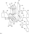
- the Fig. 1 shows a schematic perspective view of a first embodiment of a device, generally designated by reference numeral 100, for signal exchange between a controller and at least two field devices.
- the device 100 comprises a carrier 102, which comprises a control interface 104 and at least two slots 106.
- the control interface 104 is designed for the connection 108.1 of at least two electrical line channels 108 of the controller 200.
- the at least two slots 106 are each designed for the detachable mechanical connection 106.1 of a module 110 and for the passage 106.2 of at least one of the line channels 108 to the respective module 110.
- the device 100 comprises one or more modules 110, each of which comprises a carrier-side slot interface 112 and a field-side input and/or output interface 114 (EA interface, also I/O interface or in technical terms "I/O interface”) that is different from the slot interface 112.
- the slot interface 112 is designed for a detachable mechanical and electrical connection to one of the slots 106 of the carrier 102.
- the EA interface 114 is designed for the connection 116.1 of signal lines 116 of one of the field devices 300.
- the carrier 102 can also be referred to in technical terms as a carrier board or motherboard or can be designated with "B1" in the figures.
- the controller 200 can be a microcontroller or a programmable logic controller (PLC).
- PLC programmable logic controller
- Each field device 300 can include at least one sensor and/or at least one actuator.
- the field devices 300 can be designated with "F j " in the figures for the j-th field device 300.
- the field devices 300 can be collectively referred to as a field.
- a module “M1" of the modules 110 is plugged into the slot 106 labeled "S1".
- the slot 106 for the module “M1” comprises a mechanical contact surface which is designed for a (preferably non-destructive) detachable mechanical connection 106.1 with the respective module 110.
- the slot 106 comprises a guide perpendicular to a plane of the carrier 102 (preferably at corners of the contact surface "S1") for longitudinal guidance of the module 110 and/or a lock for detachable fastening of the module 110.
- the module 110 designated “M1” comprises a module-side connector half "X2" at the slot interface 112.
- the module-side connector half “X2" is designed to contact the carrier-side connector half "X1" for the feedthrough 106.2 when the respective module 110 is mechanically fastened in the corresponding slot 106 designated “S1".
- the slot interface 112 is arranged on a first edge or on a first side of the module 110, and the field-side IO interface 114 is arranged on a second edge or second side of the same module 110 that is different from the first edge or first side.
- the first edge and the second edge or the first and the second side are opposite one another on the module 110.
- the first edge and the second edge or the first and the second side have a corner of the module 110 in common, meet at a corner of the module 110 or border one another.
- the carrier-side slot interface 112 can also be referred to as a carrier connection.
- the field-side IO interface 114 can also be referred to as a field connection.
- the field-side IO interface 114 can include a socket (also: field socket).
- the field-side IO interface 114 is designated "X3".
- a connection 116.1 (designated, for example, XF1) of the respective field device 300 can be connected to the field-side IO interface 114 (for example plugged into the IO interface 114).
- the field device 300 can be a sensor or actuator.
- connection 116.1 of the signal lines 116 of the respective field device 300 can comprise a plug.
- the connection 116.1 of the signal lines 116 of the respective field device 300 can be referred to as a field plug.
- all IO interfaces 114 for example, all field sockets and/or all in Fig. 1 or 2 IO interfaces 114 designated “X3", “X6", “X9” etc.) or all connections 116.1 (for example, all field connectors and/or all in Fig. 1 connections designated “XF1" to "XF3") are identical in construction.
- a connection 116.1 for example the connection "XF1" can also be plugged into the IO interface 114 of another module 110.
- the controller 200 is designed to read or write (for example twice) the corresponding two or more modules, each of which is connected to the same field device 300, in particular in the event of a fault and/or in the event of redundancy.
- the embodiment of the device allows variable adaptation in the event of servicing, whereby a different channel than the one originally used can be selected.
- a duplicate design and the same functional blocks (e.g. for a digital output "DO") of two or more modules 110 if one output fails, functionality can be achieved with another output of another module 110 by replugging the XFj connector.
- controller 200 it is also possible for the controller 200 to be designed to program and/or control two different program sequence functions on, for example, two digital outputs (DO1 and DO2). Depending on the need, this corresponding other function can then be provided for the actuator by switching the plug from DO1 to DO2.
- a module 110 in a modular manner by inserting signal processing and/or conductive components between the slot interface 112 and the IO interface 114.
- not all field devices 300 have to be connected to the controller 200 via plugged-in modules 110.
- the central connection X1 can be used for the through-line 106.2 at the slot 106 in order to directly contact the field connector 116.1 (e.g. XF1). This minimizes hardware expenditure. This can be done for simple applications without additional galvanic isolation and/or for small signals that can be generated directly from the controller, for example.
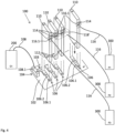
- Fig. 2 shows schematically a perspective view of a second embodiment of the device 100.
- the second embodiment can be implemented on its own or as a further development of the first embodiment.
- the corresponding module 110 e.g. the module "M1" or, in the example of the Fig. 2 , the module "M3”
- the corresponding field device 300 for example the sensor and/or the actuator
- connection 116.1 for example with the connector XF1 or XF3
- the corresponding slot for example the slot "S1" or "S3"
- all IO interfaces 114 for example, all field sockets and/or all in Fig. 1 or 2 with "X3", “X6", “X9” etc. designated IO interfaces 114) and all slots 106 with regard to their contacting to the feedthrough 106.2 (for example the connector halves "X1", “X4", "X7” etc.) are identical in construction, for example so that the connection 116.1 can be electrically connected optionally to one of the modules 110 or one of the slots 106.
- the modules 110 can be signal processing modules.
- the modules 110 are initially arranged in slots of a carrier, for example if necessary for signal processing.
- At least one module 110 in order to increase the variability, it can be provided that at least one module 110, preferably each module 110, has at least two interfaces 112 and 114 in order to establish a connection with a controller 200 (for example a controller system) or with the respective field device 300.
- a controller 200 for example a controller system
- a slot interface 112 for connection to the slot 106 and a further IO interface 114 for a connection 116.1 (for example a plug connection) for the Signal lines 116 (e.g. for wiring) to the field device 300 are provided.
- Each module 110 can be enclosed in a housing.
- the interfaces 112 and 114 are preferably arranged on different sides of the housing, for example so that one interface 112 is arranged on one side of the housing and the other interface 114 is arranged on another side.
- the latter side is preferably accessible for the connection 116.1 (for example a plug connection), in particular from the outside for connection and disconnection processes, for example when the module is plugged into the slot 106.
- connection and disconnection of the module 110 is preferably carried out by connecting and disconnecting a plug provided for the respective module 110 (for example field plug 116.1 or carrier-side feedthrough 106.2) to and from the relevant interface 114 or 112.
- Embodiments of the device 100 can offer the advantage of enabling a simple adaptation or replacement of a module 110 on a carrier 102. Alternatively or additionally, a variable adaptation of the field side to any or a single IO channel or line channel may be possible.
- This open, pluggable design to the field can resemble a cable harness.
- the ability to replace the cable harness allows for easy migration and/or adaptability to different requirements.
- Embodiments of the device 100 can implement the EA interface 114 on at least one module 110, while the other modules are implemented, for example, in accordance with the document US 9 971 727 can be connected to the controller 200 and the field devices 300. This offers further Freedom for modular design and individual adaptability of the system.
- Each embodiment of the device 100 can additionally comprise a mechanical connection between the EA interface 114 and the connection 116.1.
- individual sockets or plugs with a mechanical connection can be provided for at least one of the modules 110, which can be arranged on a frame or a housing of the respective module 110.
- the mechanical connection can comprise, for example, a locking mechanism and/or a pivoting device that is designed to pivot the connection 116.1 (for example the plugs) onto and/or away from the EA interface 114. This can simplify handling when connecting or disconnecting the field devices 300.
- the embodiment of the device 100 can include a mechanical connection between the slot 106 and the slot interface 112.
- a mechanical connection can be provided for at least one of the modules 110, which can be arranged on a frame or a housing of the carrier 102.
- the mechanical connection can, for example, comprise a locking mechanism and/or a pivoting device that is designed to pivot the respective module 110 (for example its plug for the slot interface 112) onto and/or away from the slot 106. This can simplify handling when exchanging (preferably connecting or disconnecting) the modules 110.
- the frame of the carrier 102 can comprise a slot and/or a compartment at each slot 106, which is designed to enable a simpler or straight-line feeding of a module 110 to the respective slot 106 of the carrier 102.
- the carrier 102 can have a back wiring 103 (also: backplane) for passing through to each of the slots 106 one or more other line channels 108 of the control interface 104.
- a back wiring 103 also: backplane
- a mechanical interface for securing the connector 116.1 for example a lock, can be provided on the IO interface 114 of one or each module 110.
- Fig. 3 shows schematically a perspective view of a third embodiment of the device 100.
- the third embodiment can be implemented on its own or as a further development of the first and/or second embodiment.
- the signal lines 116 of two, three or more field devices 300 comprise a cross-module connector half 118, preferably a common connector half 118 for the two, three or more field devices 300.
- the connector half 118 is simultaneously detachably connected or connectable to the IO interfaces 114 of two, three or more modules 110 for connection 116.1 of the signal lines 116 of the respective field devices 300.
- the slot interfaces 112 of the respective modules 110 are mechanically and electrically connected to adjacent slots 106 of the carrier 102.
- Fig. 4 shows schematically a perspective view of a fourth embodiment of the device 100.
- the fourth embodiment can be implemented on its own or as a further development of the first, second and/or third embodiment.
- the signal line 116 of one or each field device 300 can comprise a cross-module connector half 118', which is simultaneously detachably connected or connectable to the IO interfaces 114 of at least two modules 110 for connection 116.1 of the signal line 116 of one of the field devices 300 to the plurality of modules 110.
- the redundancy i.e. redundant wiring of a field device 300 with at least two modules 110 and/or redundant signal output to an actuator 300 or redundant signal detection from a sensor 300 by the cross-module connector half 118' can be predetermined.
- the signal lines 116 of the field device "F2" are connected to two different modules 110 by means of the cross-module connector half 118'.
- the slot interfaces 112 of the respective modules 110 are mechanically and electrically connected to adjacent slots 106 of the carrier 102.
Landscapes
- Engineering & Computer Science (AREA)
- Automation & Control Theory (AREA)
- Microelectronics & Electronic Packaging (AREA)
- Physics & Mathematics (AREA)
- General Physics & Mathematics (AREA)
- Programmable Controllers (AREA)
Claims (15)
- Dispositif (100) pour l'échange de signaux entre un système de contrôle (200) et au moins deux dispositifs de terrain (300), comprenant:une base (102) ; etun ou plusieurs modules (110),la base (102) comprenant une interface de contrôle (104) et au moins deux emplacements (106),caractérisé en ce quel'interface de contrôle (104) est configurée pour une connexion (108.1) à au moins deux canaux de câblage électrique (108) du système de contrôle (200), et chacun des au moins deux emplacements (106) est configuré pour une connexion mécanique amovible (106.1) avec un de ou les plusieurs modules (110) et pour faire passer (106.2) au moins un des canaux de câblage (108) vers le module respectif (110); eten ce que le module (110) ou les plusieurs modules (110) comprennent chacun une interface d'emplacement côté base (112) et une interface d'entrée et/ou de sortie côté terrain, interface E/S (114), différente de l'interface d'emplacement (112), dans laquelle l'interface d'emplacement (112) est configurée pour se connecter mécaniquement et électriquement de manière amovible avec l'un des emplacements (106) de la base (102), et l'interface E/S (114) est configurée pour une connexion (116.1) aux lignes de signaux (116) de l'un des dispositifs sur le terrain (300).
- Dispositif (100) selon la revendication 1, dans lequel la base (102) comprend un fond de panier (103) pour faire passer (106.2) le au moins un des canaux de câblage (108) vers le module respectif (110).
- Dispositif (100) selon la revendication 1 ou 2, dans lequel l'interface de contrôle (104) de la base (102) comprend un demi-connecteur enfichable, de préférence une prise, configuré pour se connecter (108.1) aux au moins deux canaux de câblage électrique (108) du système de contrôle (200).
- Dispositif (100) selon l'une quelconque des revendications 1 à 3, dans lequel l'interface E/S (114) d'un ou de chaque module (110) comprend un demi-connecteur enfichable, de préférence une prise, configuré pour se connecter (116.1) aux lignes de signaux (116) du dispositif de terrain (300) respectif.
- Dispositif (100) selon l'une quelconque des revendications 1 à 4, comprend en outre les lignes de signaux (116) d'une pluralité de dispositifs de terrain (300), les lignes de signaux (116) de chacun de la pluralité de dispositifs de terrain (300) comprenant un demi-connecteur enfichable qui est connecté de manière amovible ou connectable à l'interface E/S (114) du module respectif (110) pour se connecter (116.1) aux lignes de signaux (116) du dispositif de terrain respectif (300).
- Dispositif (100) selon l'une quelconque des revendications 1 à 5, comprend en outre les lignes de signaux (116) d'une pluralité de dispositifs de terrain (300), dans lequel les lignes de signaux (116) de la pluralité de dispositifs de terrain (300) comprennent une moitié de connecteur enfichable (118) s'étendant sur les modules qui est simultanément connectée de manière amovible ou connectable aux interfaces E/S (114) des modules respectifs (110) pour connecter (116.1) les lignes de signaux (116) de la pluralité de dispositifs de terrain (300),
de préférence, les interfaces des emplacements (112) des modules respectifs (110) sont connectées mécaniquement et électriquement aux emplacements adjacents (106) de la base (102). - Dispositif (100) selon l'une quelconque des revendications 1 à 6, comprend en outre les lignes de signaux (116) de l'un des dispositifs de terrain (300), dans lequel les lignes de signaux (116) de l'un des dispositifs de terrain (300) comprennent une moitié de connecteur enfichable (118') s'étendant sur des modules qui est simultanément connectée ou connectable, de manière amovible, aux interfaces E/S (114) d'au moins deux modules (110) pour connecter (116.1) les lignes de signaux (116) de l'un des dispositifs de terrain (300) à la pluralité de modules (110),
de préférence dans lequel les interfaces des emplacements (112) des au moins deux modules (110) sont connectées mécaniquement et électriquement à des emplacements adjacents (106) de la base (102). - Dispositif (100) selon l'une quelconque des revendications 1 à 7, comprenant en outre les lignes de signaux (116) d'au moins un dispositif de terrain (300), dans lequel les lignes de signaux (116) du dispositif de terrain (300) comprennent un demi-connecteur enfichable qui est connecté ou connectable, de manière amovible, directement à l'une des interfaces de contrôle (104) de la base (102) pour connecter (116.1) les lignes de signaux (116) du dispositif de terrain (300) respectif.
- Dispositif (100) selon l'une quelconque des revendications 1 à 8, dans lequel toutes les interfaces E/S (114) sont de construction identique et/ou toutes les connexions (116.1) des lignes de signaux (116) sont de construction identique.
- Dispositif (100) selon l'une quelconque des revendications 1 à 9, dans lequel l'interface d'entrée/sortie (114) et l'interface d'emplacement (112) de chaque module (110) sont séparées spatialement l'une de l'autre.
- Dispositif (100) selon l'une quelconque des revendications 1 à 10, dans lequel l'interface E/S (114) et l'interface d'emplacement (112) de chaque module (110) sont disposées sur des bords différents du module respectif (110) et/ou sur des côtés différents d'un boîtier de module du module respectif (110).
- Dispositif (100) selon l'une quelconque des revendications 1 à 11, dans lequel la base (102) est configuré pour faire passer différents canaux de câblage (108) du système de contrôle (200) à différents emplacements (106), et/oudans lequel la base (102) est configurée pour faire passer à chaque emplacement (106) un des canaux de câblage (108) du système de contrôle (200), et/oudans lequel la base (102) est configuré pour faire passer les canaux de câblage (108) au module respectif sans traitement de signal propre et/ou avec une réponse de signal linéaire.
- Dispositif (100) selon l'une quelconque des revendications 1 à 12, dans lequel les au moins deux emplacements (106) de la base (102) sont configurés pour connecter mécaniquement au moins deux modules indépendamment l'un de l'autre à la base (102) et/ou pour déconnecter mécaniquement au moins deux modules indépendamment l'un de l'autre de la base (102).
- Dispositif (100) selon l'une des revendications 1 à 13, dans lequel le module (110), ou au moins l'un ou chacun des modules (110) comprend une unité de traitement des signaux configurée pour émettre et/ou acquérir des signaux à l'interface E/S (114), pour recevoir et/ou transmettre des signaux à l'interface d'emplacement (112), et pour traiter les signaux reçus dans les signaux d'émission et/ou pour traiter les signaux acquis dans les signaux transmis.
- Dispositif (100) selon l'une quelconque des revendications 1 à 14, comprenant en outre un boîtier de dispositif, dans lequel la base (102) est disposée, et dans lequel le ou les modules (110) sont disposés ou peuvent être disposés dans l'état connecté avec la base (102), optionnellement l'interface E/S (114) étant accessible depuis l'extérieur du boîtier de dispositif à travers une ouverture dans le boîtier de dispositif dans l'état connecté avec la base (102) du module respectif (110).
Applications Claiming Priority (2)
| Application Number | Priority Date | Filing Date | Title |
|---|---|---|---|
| DE102019135089.1A DE102019135089A1 (de) | 2019-12-19 | 2019-12-19 | Vorrichtung zum Signalaustausch zwischen Steuerung und Feldgeräten |
| PCT/EP2020/085555 WO2021122318A1 (fr) | 2019-12-19 | 2020-12-10 | Appareil d'échange de signaux entre un dispositif de commande et des dispositifs de terrain |
Publications (2)
| Publication Number | Publication Date |
|---|---|
| EP4078302A1 EP4078302A1 (fr) | 2022-10-26 |
| EP4078302B1 true EP4078302B1 (fr) | 2024-11-06 |
Family
ID=73834526
Family Applications (1)
| Application Number | Title | Priority Date | Filing Date |
|---|---|---|---|
| EP20824210.7A Active EP4078302B1 (fr) | 2019-12-19 | 2020-12-10 | Appareil d'échange de signaux entre un dispositif de commande et des dispositifs de terrain |
Country Status (4)
| Country | Link |
|---|---|
| US (1) | US20230014118A1 (fr) |
| EP (1) | EP4078302B1 (fr) |
| DE (1) | DE102019135089A1 (fr) |
| WO (1) | WO2021122318A1 (fr) |
Families Citing this family (1)
| Publication number | Priority date | Publication date | Assignee | Title |
|---|---|---|---|---|
| LU504839B1 (de) * | 2023-08-01 | 2025-02-03 | Phoenix Contact Gmbh & Co | Intelligente Steuerung |
Citations (15)
| Publication number | Priority date | Publication date | Assignee | Title |
|---|---|---|---|---|
| DE19512372A1 (de) | 1995-04-01 | 1996-10-10 | Abb Patent Gmbh | Einrichtung zur eigensicheren Signalanpassung |
| DE19619886A1 (de) | 1996-05-17 | 1997-11-20 | Phoenix Contact Gmbh & Co | Steuer- und Datenübertragungsanlage mit teilweise redundantem Bussystem |
| DE19855869C1 (de) | 1998-12-03 | 2000-05-18 | Schmersal K A Gmbh & Co | Feldbusanschlußeinrichtung |
| EP1014531A2 (fr) | 1998-12-23 | 2000-06-28 | Hans Turck Gmbh & Co. KG | Appareil d'alimentation en énergie électrique pour composants électroniques anti-déflagrant |
| EP1174781A2 (fr) | 2000-05-22 | 2002-01-23 | CEAG Sicherheitstechnik GmbH | Appareil de transmission de signal |
| WO2004075357A1 (fr) | 2003-02-20 | 2004-09-02 | Rockwell Automation Technologies, Inc. | Dispositif electrique modulaire muni d'un joint ameliore |
| WO2010023545A1 (fr) | 2008-08-29 | 2010-03-04 | Phoenix Contact Development & Manufacturing, Inc. | Système de commande modulaire à sécurité intrinsèque |
| US20120047288A1 (en) | 2010-08-20 | 2012-02-23 | Rockwell Automation Technologies, Inc. | Input/Output Devices Having Re-Configurable Functionality |
| EP2869146A1 (fr) | 2013-10-31 | 2015-05-06 | Yokogawa Electric Corporation | Module d'E/S |
| US20160259752A1 (en) | 2014-06-02 | 2016-09-08 | Phoenix Contact Development and Manufacturing, Inc. | Universal I/O Signal Interposer System |
| EP3312687A2 (fr) | 2016-10-20 | 2018-04-25 | Rockwell Automation Technologies, Inc. | Système d'entrée/sortie (e/s) sur machine comportant des connexions modulaires |
| WO2019008032A1 (fr) | 2017-07-04 | 2019-01-10 | Weidmüller Interface GmbH & Co. KG | Commande et système de commande modulaire d'un système d'automatisation industriel |
| EP3435749A1 (fr) | 2017-07-28 | 2019-01-30 | Yazaki Europe Ltd | Unité de commande électronique à architecture flexible |
| EP3441984A1 (fr) | 2007-07-20 | 2019-02-13 | Asco, L.P. | Système de bus électrique modulaire |
| JP2019079458A (ja) | 2017-10-27 | 2019-05-23 | 島津システムソリューションズ株式会社 | プロセス制御装置 |
Family Cites Families (1)
| Publication number | Priority date | Publication date | Assignee | Title |
|---|---|---|---|---|
| US9411769B2 (en) * | 2006-09-19 | 2016-08-09 | Fisher-Rosemount Systems, Inc. | Apparatus and methods to communicatively couple field devices to controllers in a process control system |
-
2019
- 2019-12-19 DE DE102019135089.1A patent/DE102019135089A1/de active Pending
-
2020
- 2020-12-10 US US17/786,548 patent/US20230014118A1/en active Pending
- 2020-12-10 EP EP20824210.7A patent/EP4078302B1/fr active Active
- 2020-12-10 WO PCT/EP2020/085555 patent/WO2021122318A1/fr not_active Ceased
Patent Citations (23)
| Publication number | Priority date | Publication date | Assignee | Title |
|---|---|---|---|---|
| DE19512372A1 (de) | 1995-04-01 | 1996-10-10 | Abb Patent Gmbh | Einrichtung zur eigensicheren Signalanpassung |
| DE19619886A1 (de) | 1996-05-17 | 1997-11-20 | Phoenix Contact Gmbh & Co | Steuer- und Datenübertragungsanlage mit teilweise redundantem Bussystem |
| DE19619886C2 (de) | 1996-05-17 | 2002-01-24 | Phoenix Contact Gmbh & Co | Steuer- und Datenübertragungsanlage mit teilweise redundantem Bussystem |
| DE19855869C1 (de) | 1998-12-03 | 2000-05-18 | Schmersal K A Gmbh & Co | Feldbusanschlußeinrichtung |
| EP1006768A2 (fr) | 1998-12-03 | 2000-06-07 | K.A. SCHMERSAL GmbH & Co. | Dispositif bus de secteur |
| EP1014531B1 (fr) | 1998-12-23 | 2010-03-10 | Hans Turck Gmbh & Co. KG | Appareil d'alimentation en énergie électrique pour composants électroniques anti-déflagrant |
| EP1014531A2 (fr) | 1998-12-23 | 2000-06-28 | Hans Turck Gmbh & Co. KG | Appareil d'alimentation en énergie électrique pour composants électroniques anti-déflagrant |
| EP1174781A2 (fr) | 2000-05-22 | 2002-01-23 | CEAG Sicherheitstechnik GmbH | Appareil de transmission de signal |
| WO2004075357A1 (fr) | 2003-02-20 | 2004-09-02 | Rockwell Automation Technologies, Inc. | Dispositif electrique modulaire muni d'un joint ameliore |
| EP1595312B1 (fr) | 2003-02-20 | 2007-09-26 | Rockwell Automation Technologies, Inc. | Dispositif electrique modulaire muni d'un joint ameliore |
| EP3441984A1 (fr) | 2007-07-20 | 2019-02-13 | Asco, L.P. | Système de bus électrique modulaire |
| EP2332227B1 (fr) | 2008-08-29 | 2018-09-26 | Phoenix Contact GmbH & Co. KG | Système de commande modulaire à sécurité intrinsèque |
| WO2010023545A1 (fr) | 2008-08-29 | 2010-03-04 | Phoenix Contact Development & Manufacturing, Inc. | Système de commande modulaire à sécurité intrinsèque |
| US20120047288A1 (en) | 2010-08-20 | 2012-02-23 | Rockwell Automation Technologies, Inc. | Input/Output Devices Having Re-Configurable Functionality |
| US20180341609A1 (en) | 2013-10-31 | 2018-11-29 | Yokogawa Electric Corporation | I/o module |
| EP2869146B1 (fr) | 2013-10-31 | 2019-01-30 | Yokogawa Electric Corporation | Module d'E/S |
| EP2869146A1 (fr) | 2013-10-31 | 2015-05-06 | Yokogawa Electric Corporation | Module d'E/S |
| US9971727B2 (en) | 2014-06-02 | 2018-05-15 | Phoenix Contact Development and Manufacturing, Inc. | Universal I/O signal interposer system |
| US20160259752A1 (en) | 2014-06-02 | 2016-09-08 | Phoenix Contact Development and Manufacturing, Inc. | Universal I/O Signal Interposer System |
| EP3312687A2 (fr) | 2016-10-20 | 2018-04-25 | Rockwell Automation Technologies, Inc. | Système d'entrée/sortie (e/s) sur machine comportant des connexions modulaires |
| WO2019008032A1 (fr) | 2017-07-04 | 2019-01-10 | Weidmüller Interface GmbH & Co. KG | Commande et système de commande modulaire d'un système d'automatisation industriel |
| EP3435749A1 (fr) | 2017-07-28 | 2019-01-30 | Yazaki Europe Ltd | Unité de commande électronique à architecture flexible |
| JP2019079458A (ja) | 2017-10-27 | 2019-05-23 | 島津システムソリューションズ株式会社 | プロセス制御装置 |
Also Published As
| Publication number | Publication date |
|---|---|
| US20230014118A1 (en) | 2023-01-19 |
| DE102019135089A1 (de) | 2021-06-24 |
| EP4078302A1 (fr) | 2022-10-26 |
| WO2021122318A1 (fr) | 2021-06-24 |
Similar Documents
| Publication | Publication Date | Title |
|---|---|---|
| EP1174781B1 (fr) | Appareil de transmission de signal | |
| EP3262907B1 (fr) | Unité modulaire de raccordement d'appareil de terrain | |
| EP3888430B1 (fr) | Module de base et module fonctionnel pour un système d'armoire électrique et système d'armoire électrique | |
| EP3735808B1 (fr) | Système de commande et procédé de montage d'un système de commande | |
| DE102022117693A1 (de) | Station zum Einsatz in einem Feldnetz zwischen einem oder mehreren Feldgeräten und einer Zentraleinheit sowie in einen Modulträger auswechselbar einsteckbares Switch-Modul | |
| EP0879445A1 (fr) | Dispositif permettant d'adapter des signaux de maniere intrinsequement fiable | |
| DE102009054155A1 (de) | Ein- und/oder Ausgabe-Sicherheitsmodul für ein Automatisierungsgerät | |
| DE4416795C2 (de) | Redundant konfigurierbares Übertragungssystem zum Datenaustausch und Verfahren zu dessen Betrieb | |
| DE10135980C1 (de) | Anordnung zum Anschluß von dezentral und prozessnah angeordneten Feldgeräten an eine entfernte zentrale Einrichtung | |
| EP2829927B1 (fr) | Unité modulaire de raccordement d'appareil de terrain | |
| EP2214068A1 (fr) | Système d'automatisation doté d'un module de matrice programmable | |
| DE102021101883A1 (de) | Drucksensor | |
| EP4078302B1 (fr) | Appareil d'échange de signaux entre un dispositif de commande et des dispositifs de terrain | |
| WO2021144290A1 (fr) | Dispositif de traitement de signaux entre une commande et des appareils de terrain | |
| EP2698677A1 (fr) | Système périphérique | |
| DE102017120483A1 (de) | Integrierte Anordnung mit einer elektrischen Spannungsversorgung und einer Kommunikationsschnittstelle | |
| DE4013815C2 (de) | Steuerschaltung für Maschinen | |
| EP3660603B1 (fr) | Module fonctionnel pouvant être disposé en rang, adapté bus | |
| EP0888707B1 (fr) | Module avec ensemble de circuits | |
| EP0940066B1 (fr) | Dispositif de codage d'unites enfichables et dispositif de connexion de lignes exterieures au moyen d'un tel dispositif de codage | |
| LU101864B1 (de) | Technik zum Verarbeiten und Austauschen von Feldsignalen | |
| DE102007019048A1 (de) | Modulare automatisierungstechnische Einrichtung | |
| DE102016015616B4 (de) | Modul-System mit Busanbindung und Direkt-Drahtverbindung | |
| DE202008009599U1 (de) | Signalübertragungseinrichtung | |
| DE102020115967A1 (de) | Technik zum Verarbeiten und Austauschen von Feldsignalen |
Legal Events
| Date | Code | Title | Description |
|---|---|---|---|
| STAA | Information on the status of an ep patent application or granted ep patent |
Free format text: STATUS: UNKNOWN |
|
| STAA | Information on the status of an ep patent application or granted ep patent |
Free format text: STATUS: THE INTERNATIONAL PUBLICATION HAS BEEN MADE |
|
| PUAI | Public reference made under article 153(3) epc to a published international application that has entered the european phase |
Free format text: ORIGINAL CODE: 0009012 |
|
| STAA | Information on the status of an ep patent application or granted ep patent |
Free format text: STATUS: REQUEST FOR EXAMINATION WAS MADE |
|
| 17P | Request for examination filed |
Effective date: 20220701 |
|
| AK | Designated contracting states |
Kind code of ref document: A1 Designated state(s): AL AT BE BG CH CY CZ DE DK EE ES FI FR GB GR HR HU IE IS IT LI LT LU LV MC MK MT NL NO PL PT RO RS SE SI SK SM TR |
|
| DAV | Request for validation of the european patent (deleted) | ||
| DAX | Request for extension of the european patent (deleted) | ||
| P01 | Opt-out of the competence of the unified patent court (upc) registered |
Effective date: 20230512 |
|
| GRAP | Despatch of communication of intention to grant a patent |
Free format text: ORIGINAL CODE: EPIDOSNIGR1 |
|
| STAA | Information on the status of an ep patent application or granted ep patent |
Free format text: STATUS: GRANT OF PATENT IS INTENDED |
|
| INTG | Intention to grant announced |
Effective date: 20240617 |
|
| GRAS | Grant fee paid |
Free format text: ORIGINAL CODE: EPIDOSNIGR3 |
|
| GRAA | (expected) grant |
Free format text: ORIGINAL CODE: 0009210 |
|
| STAA | Information on the status of an ep patent application or granted ep patent |
Free format text: STATUS: THE PATENT HAS BEEN GRANTED |
|
| AK | Designated contracting states |
Kind code of ref document: B1 Designated state(s): AL AT BE BG CH CY CZ DE DK EE ES FI FR GB GR HR HU IE IS IT LI LT LU LV MC MK MT NL NO PL PT RO RS SE SI SK SM TR |
|
| REG | Reference to a national code |
Ref country code: GB Ref legal event code: FG4D Free format text: NOT ENGLISH |
|
| REG | Reference to a national code |
Ref country code: CH Ref legal event code: EP |
|
| REG | Reference to a national code |
Ref country code: DE Ref legal event code: R096 Ref document number: 502020009726 Country of ref document: DE |
|
| REG | Reference to a national code |
Ref country code: IE Ref legal event code: FG4D Free format text: LANGUAGE OF EP DOCUMENT: GERMAN |
|
| REG | Reference to a national code |
Ref country code: LT Ref legal event code: MG9D |
|
| REG | Reference to a national code |
Ref country code: NL Ref legal event code: MP Effective date: 20241106 |
|
| PG25 | Lapsed in a contracting state [announced via postgrant information from national office to epo] |
Ref country code: HR Free format text: LAPSE BECAUSE OF FAILURE TO SUBMIT A TRANSLATION OF THE DESCRIPTION OR TO PAY THE FEE WITHIN THE PRESCRIBED TIME-LIMIT Effective date: 20241106 Ref country code: IS Free format text: LAPSE BECAUSE OF FAILURE TO SUBMIT A TRANSLATION OF THE DESCRIPTION OR TO PAY THE FEE WITHIN THE PRESCRIBED TIME-LIMIT Effective date: 20250306 Ref country code: PT Free format text: LAPSE BECAUSE OF FAILURE TO SUBMIT A TRANSLATION OF THE DESCRIPTION OR TO PAY THE FEE WITHIN THE PRESCRIBED TIME-LIMIT Effective date: 20250306 |
|
| PG25 | Lapsed in a contracting state [announced via postgrant information from national office to epo] |
Ref country code: FI Free format text: LAPSE BECAUSE OF FAILURE TO SUBMIT A TRANSLATION OF THE DESCRIPTION OR TO PAY THE FEE WITHIN THE PRESCRIBED TIME-LIMIT Effective date: 20241106 Ref country code: NL Free format text: LAPSE BECAUSE OF FAILURE TO SUBMIT A TRANSLATION OF THE DESCRIPTION OR TO PAY THE FEE WITHIN THE PRESCRIBED TIME-LIMIT Effective date: 20241106 |
|
| PG25 | Lapsed in a contracting state [announced via postgrant information from national office to epo] |
Ref country code: BG Free format text: LAPSE BECAUSE OF FAILURE TO SUBMIT A TRANSLATION OF THE DESCRIPTION OR TO PAY THE FEE WITHIN THE PRESCRIBED TIME-LIMIT Effective date: 20241106 |
|
| PG25 | Lapsed in a contracting state [announced via postgrant information from national office to epo] |
Ref country code: ES Free format text: LAPSE BECAUSE OF FAILURE TO SUBMIT A TRANSLATION OF THE DESCRIPTION OR TO PAY THE FEE WITHIN THE PRESCRIBED TIME-LIMIT Effective date: 20241106 |
|
| PG25 | Lapsed in a contracting state [announced via postgrant information from national office to epo] |
Ref country code: NO Free format text: LAPSE BECAUSE OF FAILURE TO SUBMIT A TRANSLATION OF THE DESCRIPTION OR TO PAY THE FEE WITHIN THE PRESCRIBED TIME-LIMIT Effective date: 20250206 |
|
| PG25 | Lapsed in a contracting state [announced via postgrant information from national office to epo] |
Ref country code: GR Free format text: LAPSE BECAUSE OF FAILURE TO SUBMIT A TRANSLATION OF THE DESCRIPTION OR TO PAY THE FEE WITHIN THE PRESCRIBED TIME-LIMIT Effective date: 20250207 Ref country code: LV Free format text: LAPSE BECAUSE OF FAILURE TO SUBMIT A TRANSLATION OF THE DESCRIPTION OR TO PAY THE FEE WITHIN THE PRESCRIBED TIME-LIMIT Effective date: 20241106 |
|
| PG25 | Lapsed in a contracting state [announced via postgrant information from national office to epo] |
Ref country code: PL Free format text: LAPSE BECAUSE OF FAILURE TO SUBMIT A TRANSLATION OF THE DESCRIPTION OR TO PAY THE FEE WITHIN THE PRESCRIBED TIME-LIMIT Effective date: 20241106 |
|
| PG25 | Lapsed in a contracting state [announced via postgrant information from national office to epo] |
Ref country code: RS Free format text: LAPSE BECAUSE OF FAILURE TO SUBMIT A TRANSLATION OF THE DESCRIPTION OR TO PAY THE FEE WITHIN THE PRESCRIBED TIME-LIMIT Effective date: 20250206 |
|
| PG25 | Lapsed in a contracting state [announced via postgrant information from national office to epo] |
Ref country code: SM Free format text: LAPSE BECAUSE OF FAILURE TO SUBMIT A TRANSLATION OF THE DESCRIPTION OR TO PAY THE FEE WITHIN THE PRESCRIBED TIME-LIMIT Effective date: 20241106 |
|
| PG25 | Lapsed in a contracting state [announced via postgrant information from national office to epo] |
Ref country code: DK Free format text: LAPSE BECAUSE OF FAILURE TO SUBMIT A TRANSLATION OF THE DESCRIPTION OR TO PAY THE FEE WITHIN THE PRESCRIBED TIME-LIMIT Effective date: 20241106 |
|
| PG25 | Lapsed in a contracting state [announced via postgrant information from national office to epo] |
Ref country code: EE Free format text: LAPSE BECAUSE OF FAILURE TO SUBMIT A TRANSLATION OF THE DESCRIPTION OR TO PAY THE FEE WITHIN THE PRESCRIBED TIME-LIMIT Effective date: 20241106 |
|
| PG25 | Lapsed in a contracting state [announced via postgrant information from national office to epo] |
Ref country code: RO Free format text: LAPSE BECAUSE OF FAILURE TO SUBMIT A TRANSLATION OF THE DESCRIPTION OR TO PAY THE FEE WITHIN THE PRESCRIBED TIME-LIMIT Effective date: 20241106 |
|
| PG25 | Lapsed in a contracting state [announced via postgrant information from national office to epo] |
Ref country code: SK Free format text: LAPSE BECAUSE OF FAILURE TO SUBMIT A TRANSLATION OF THE DESCRIPTION OR TO PAY THE FEE WITHIN THE PRESCRIBED TIME-LIMIT Effective date: 20241106 |
|
| PG25 | Lapsed in a contracting state [announced via postgrant information from national office to epo] |
Ref country code: CZ Free format text: LAPSE BECAUSE OF FAILURE TO SUBMIT A TRANSLATION OF THE DESCRIPTION OR TO PAY THE FEE WITHIN THE PRESCRIBED TIME-LIMIT Effective date: 20241106 |
|
| REG | Reference to a national code |
Ref country code: CH Ref legal event code: PL |
|
| REG | Reference to a national code |
Ref country code: DE Ref legal event code: R026 Ref document number: 502020009726 Country of ref document: DE |
|
| PLBI | Opposition filed |
Free format text: ORIGINAL CODE: 0009260 |
|
| PG25 | Lapsed in a contracting state [announced via postgrant information from national office to epo] |
Ref country code: LU Free format text: LAPSE BECAUSE OF NON-PAYMENT OF DUE FEES Effective date: 20241210 |
|
| PG25 | Lapsed in a contracting state [announced via postgrant information from national office to epo] |
Ref country code: SE Free format text: LAPSE BECAUSE OF FAILURE TO SUBMIT A TRANSLATION OF THE DESCRIPTION OR TO PAY THE FEE WITHIN THE PRESCRIBED TIME-LIMIT Effective date: 20241106 |
|
| 26 | Opposition filed |
Opponent name: PEPPERL+FUCHS SE Effective date: 20250806 |
|
| PG25 | Lapsed in a contracting state [announced via postgrant information from national office to epo] |
Ref country code: MC Free format text: LAPSE BECAUSE OF FAILURE TO SUBMIT A TRANSLATION OF THE DESCRIPTION OR TO PAY THE FEE WITHIN THE PRESCRIBED TIME-LIMIT Effective date: 20241106 |
|
| REG | Reference to a national code |
Ref country code: BE Ref legal event code: MM Effective date: 20241231 |
|
| PG25 | Lapsed in a contracting state [announced via postgrant information from national office to epo] |
Ref country code: BE Free format text: LAPSE BECAUSE OF NON-PAYMENT OF DUE FEES Effective date: 20241231 |
|
| PLAX | Notice of opposition and request to file observation + time limit sent |
Free format text: ORIGINAL CODE: EPIDOSNOBS2 |
|
| PG25 | Lapsed in a contracting state [announced via postgrant information from national office to epo] |
Ref country code: FR Free format text: LAPSE BECAUSE OF NON-PAYMENT OF DUE FEES Effective date: 20250106 |
|
| PG25 | Lapsed in a contracting state [announced via postgrant information from national office to epo] |
Ref country code: CH Free format text: LAPSE BECAUSE OF NON-PAYMENT OF DUE FEES Effective date: 20241231 |
|
| PG25 | Lapsed in a contracting state [announced via postgrant information from national office to epo] |
Ref country code: IE Free format text: LAPSE BECAUSE OF NON-PAYMENT OF DUE FEES Effective date: 20241210 |
|
| GBPC | Gb: european patent ceased through non-payment of renewal fee |
Effective date: 20250206 |
|
| PG25 | Lapsed in a contracting state [announced via postgrant information from national office to epo] |
Ref country code: GB Free format text: LAPSE BECAUSE OF NON-PAYMENT OF DUE FEES Effective date: 20250206 |
|
| PGFP | Annual fee paid to national office [announced via postgrant information from national office to epo] |
Ref country code: AT Payment date: 20260113 Year of fee payment: 5 |
|
| PGFP | Annual fee paid to national office [announced via postgrant information from national office to epo] |
Ref country code: IT Payment date: 20251218 Year of fee payment: 6 |
|
| PLBP | Opposition withdrawn |
Free format text: ORIGINAL CODE: 0009264 |
|
| REG | Reference to a national code |
Ref country code: CH Ref legal event code: L10 Free format text: ST27 STATUS EVENT CODE: U-0-0-L10-L00 (AS PROVIDED BY THE NATIONAL OFFICE) Effective date: 20260204 |
|
| PLBB | Reply of patent proprietor to notice(s) of opposition received |
Free format text: ORIGINAL CODE: EPIDOSNOBS3 |
|
| PLBD | Termination of opposition procedure: decision despatched |
Free format text: ORIGINAL CODE: EPIDOSNOPC1 |
|
| PGFP | Annual fee paid to national office [announced via postgrant information from national office to epo] |
Ref country code: DE Payment date: 20260220 Year of fee payment: 6 |