EP2214154A2 - Videowiedergabevorrichtung - Google Patents
Videowiedergabevorrichtung Download PDFInfo
- Publication number
- EP2214154A2 EP2214154A2 EP09252691A EP09252691A EP2214154A2 EP 2214154 A2 EP2214154 A2 EP 2214154A2 EP 09252691 A EP09252691 A EP 09252691A EP 09252691 A EP09252691 A EP 09252691A EP 2214154 A2 EP2214154 A2 EP 2214154A2
- Authority
- EP
- European Patent Office
- Prior art keywords
- region
- backlight
- luminance
- value
- video
- Prior art date
- Legal status (The legal status is an assumption and is not a legal conclusion. Google has not performed a legal analysis and makes no representation as to the accuracy of the status listed.)
- Withdrawn
Links
Images









Classifications
-
- G—PHYSICS
- G06—COMPUTING OR CALCULATING; COUNTING
- G06T—IMAGE DATA PROCESSING OR GENERATION, IN GENERAL
- G06T5/00—Image enhancement or restoration
- G06T5/40—Image enhancement or restoration using histogram techniques
-
- G—PHYSICS
- G06—COMPUTING OR CALCULATING; COUNTING
- G06T—IMAGE DATA PROCESSING OR GENERATION, IN GENERAL
- G06T5/00—Image enhancement or restoration
- G06T5/90—Dynamic range modification of images or parts thereof
- G06T5/94—Dynamic range modification of images or parts thereof based on local image properties, e.g. for local contrast enhancement
-
- G—PHYSICS
- G09—EDUCATION; CRYPTOGRAPHY; DISPLAY; ADVERTISING; SEALS
- G09G—ARRANGEMENTS OR CIRCUITS FOR CONTROL OF INDICATING DEVICES USING STATIC MEANS TO PRESENT VARIABLE INFORMATION
- G09G3/00—Control arrangements or circuits, of interest only in connection with visual indicators other than cathode-ray tubes
- G09G3/20—Control arrangements or circuits, of interest only in connection with visual indicators other than cathode-ray tubes for presentation of an assembly of a number of characters, e.g. a page, by composing the assembly by combination of individual elements arranged in a matrix no fixed position being assigned to or needed to be assigned to the individual characters or partial characters
- G09G3/34—Control arrangements or circuits, of interest only in connection with visual indicators other than cathode-ray tubes for presentation of an assembly of a number of characters, e.g. a page, by composing the assembly by combination of individual elements arranged in a matrix no fixed position being assigned to or needed to be assigned to the individual characters or partial characters by control of light from an independent source
- G09G3/3406—Control of illumination source
- G09G3/342—Control of illumination source using several illumination sources separately controlled corresponding to different display panel areas, e.g. along one dimension such as lines
- G09G3/3426—Control of illumination source using several illumination sources separately controlled corresponding to different display panel areas, e.g. along one dimension such as lines the different display panel areas being distributed in two dimensions, e.g. matrix
-
- G—PHYSICS
- G06—COMPUTING OR CALCULATING; COUNTING
- G06T—IMAGE DATA PROCESSING OR GENERATION, IN GENERAL
- G06T2207/00—Indexing scheme for image analysis or image enhancement
- G06T2207/20—Special algorithmic details
- G06T2207/20004—Adaptive image processing
- G06T2207/20012—Locally adaptive
-
- G—PHYSICS
- G09—EDUCATION; CRYPTOGRAPHY; DISPLAY; ADVERTISING; SEALS
- G09G—ARRANGEMENTS OR CIRCUITS FOR CONTROL OF INDICATING DEVICES USING STATIC MEANS TO PRESENT VARIABLE INFORMATION
- G09G2320/00—Control of display operating conditions
- G09G2320/06—Adjustment of display parameters
- G09G2320/0626—Adjustment of display parameters for control of overall brightness
- G09G2320/0646—Modulation of illumination source brightness and image signal correlated to each other
-
- G—PHYSICS
- G09—EDUCATION; CRYPTOGRAPHY; DISPLAY; ADVERTISING; SEALS
- G09G—ARRANGEMENTS OR CIRCUITS FOR CONTROL OF INDICATING DEVICES USING STATIC MEANS TO PRESENT VARIABLE INFORMATION
- G09G2360/00—Aspects of the architecture of display systems
- G09G2360/16—Calculation or use of calculated indices related to luminance levels in display data
Definitions
- the present invention relates to a video display apparatus for conducting display of video by modulating a backlight depending onavideosignal, and in particular, relates to a lighting apparatus for controlling the backlight of a region corresponding to the video signal, and a video display apparatus equipped with this, as well as, a video display method.
- the display apparatus can be classified into, roughly, a display of light emission type, such as, a CRT (Cathode Ray Tube) or a plasma display panel, etc. , and a display apparatus of non-light emission type, such as, a liquid crystal display (also, it may be called a "liquid crystal display apparatus” or "a liquid crystal display panel”), etc.
- a display of light emission type such as, a CRT (Cathode Ray Tube) or a plasma display panel, etc.
- a display apparatus of non-light emission type such as, a liquid crystal display (also, it may be called a "liquid crystal display apparatus” or "a liquid crystal display panel”), etc.
- the liquid crystal display apparatus comprising a lighting apparatus (also, it may be called "a backlight") on a back surface thereof, with applying the liquid crystal display panel as the transmission type light modulator element, because of thin thickness and light weight thereof, it is adopted in various kinds of display apparatuses, such as, a monitor of a computer, a television, etc., for example.
- the backlight always emits the light at a constant brightness, irrespective of the video signal. Accordingly, the brightness is set to fit the condition where a brightness (or may be called "luminance") of the screen comes to the maximum, normally, and since the light emission is made with the same brightness even when displaying the black color and the dark picture on the screen, then unnecessary consumption is made on electric power, which does not contribute to the display.
- a brightness or may be called "luminance”
- the display does not get to be dark, sufficiently, because of leakage of a part of lights of the backlight, then a contrast within a dark room comes to be small comparing to that of the self-light emission type display apparatus, such as, the CRT, etc.
- a video display region is divided into a plural number of regions, and the luminance of the backlight is controlled for each region corresponding to the video signal, by a unit of the divided regions, and thereby achieving the energy saving, while keeping a contrast ratio to be high.
- the present invention is accomplished by taking the problem mentioned above into the consideration thereof. And, according to the present invention, an object thereof is to provide a technology for enabling to suppress the black float while reducing the unnecessary electric power of the backlight.
- the video display apparatus is characterized in that a luminance of the backlight of the region, in which an amount of leakage lights leaking from a turn-on region is equal or greater than a predetermined value, is put out, and also a light control value of the display panel is controlled, thereby suppressing the black float.
- a transmission-type display panel such as, a liquid crystal display panel therein, as the display panel
- control is made upon a transmission factor thereof, as an amount of the controlled light.
- an analysis is made upon an input video signal, so as to detect a specific picture or video, necessity to be controlled on the black float, depending on the characteristics thereof, and also obtains the position information of the turn-on region.
- a put-out region i.e., a correction region
- a lightening apparatus for controlling the luminance of the backlight of the regions corresponding to a video signal, while dividing the video display region into a plural number of regions, and a video display apparatus comprising the same therein, it is possible to control the amount of the controlled light of the display panel corresponding to the put-out regions, and thereby obtaining a video, being large in an effect of saving the electric power consumption, and suppressing the black float thereon.
- Figs. 1A to 1E show: (a) an input video signal, (b) a backlight control value when the input video signal is inputted, (c) a backlight luminance distribution, (d) a target luminance distribution, and (e) change of transmission ratio of a liquid crystal panel, of a liquid crystal display apparatus, according to a first embodiment (embodiment 1) of the present invention.
- the input video signal mentioned above is assumed to be constructed with a black picture region (for example, "0" by 8 bits expression) and a white picture region (255), and a region (102) of a backlight, which can be controlled independently, when dividing a display region (101) into a plural number of regions, is also assumed to be constructed with six (6) regions in the horizontal direction and five (5) regions in the vertical direction, i.e., 30 regions in total thereof.
- each region is/are provided one (1) or a plural number of light source(s), such as, a light emitting diode (s), etc., for example, an amount of lights (i.e., the luminance) of which can be controlled, independently.
- controlling the light source corresponding to this each region enables to control the luminance of the backlight of each region.
- This each region may sometimes be called "a backlight region", hereinafter.
- the backlight control value mentioned above corresponds to the input video signal mentioned above, wherein the backlight control value corresponding to a region, into which a while picture is inputted (also, it may be called “a turn-on region"), is determined to be a control value (for example, "255" by 8 bits expression) of bringing that region up to the maximum luminance thereof, and a backlight control value of the region, neighboring with that turn-on region, and the region where an amount of leakage lights from the turn-on region is equal to or greater than a predetermined value, is determined to be "0" .
- a control value for example, "255" by 8 bits expression
- the backlight control value corresponding to the region, into which the black picture is inputted, where the leakage light amount from the turn-on region is equal to or lower than the predetermined value, because of being apart from the turn-on region at a predetermined distance, is controlled so that it emits lights at a value ("1" by the 8 bits), being sufficiently small comparing to the region, into which the white picture is inputted, within a limit where the target luminance distribution mentioned above can be presented by changing the transmission factor of the liquid crystal panel.
- an amount of the leakage lights indicates a quantity of lights leaking from the turn-on region into the put-out region, and a value, which can be defined by a front surface luminance, etc.
- the predetermined value of the amount of the leakage lights from that turn-on region has the luminance, which is equal to or greater than 1% of the maximum luminance of the turn-on region.
- the target luminance distribution mentioned above is so determined that, within a predetermined distance from the turn-on region mentioned above, the luminance has a value, being equal to that of the black float or unrecognizable of the difference of luminance, and after the predetermined distance, the luminance mentioned above directs to "0", gradually.
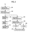
- Fig. 2 is a block diagram for showing the entire of circuits, within a liquid crystal display apparatus, according to a first embodiment of the present invention.
- the liquid crystal display apparatus of this embodiment comprises a video frame receiver portion (201), a video signal processor portion (202), a backlight controller portion (203), a video signal corrector portion (204), a backlight driver portion (205), a liquid crystal controller portion (206), a H-driver (207), a V-driver (208), a liquid crystal panel (209) and a backlight portion (210).
- Fig. 3 is a block diagram for explaining the operations of the video signal processor portion mentioned above.
- histogram detection is conducted for each plural numbers of the backlight regions, which can be controlled, independently, by a histogram detector portion (301) for each region.
- a gradation value of each pixel of the video frame, which is included in that backlight region is counted, and in case where the gradation values, being equal to or less than a predetermined upper limit gradation value (P1), and the gradation values, being equal to or greater than a predetermined lower limit gradation value (P2), occupy 90% or more of the number of pixels corresponding to that backlight region, the control signal 1 is turned "ON".
- P1 is determined to be "20", i.e., a value from 0% to 10% of the maximum gradation value ("255" if 8 bits), and "P2" to be “220”, i.e., a value from 85% to 100% of the maximum gradation value.
- a region “A4" including the white picture therein includes only the gradation value equal or less than "P1” and the gradation value equal or grater than “P2", and further it includes the gradation value equal or greater than “P2”, then the control signal 1 is turned “ON” and also the control signal 2 is turned “ON”.
- a region "A6" a half of the number of pixels of the region including an intermediate gradation picture therein, does not fit to the condition that the gradation value equal or less than "P1” and the gradation value equal or greater than "P2” occupy 90% or more of the number of pixels corresponding to the backlight region, then the control signal 1 is turned “OFF” and the control signal 2 is turned “OFF".
- control filter(303) After completing the histogram detection for all of the backlight regions mentioned above, within the control filter(303) is determined a control method for the video frame mentioned above.
- control signal 1 of all the backlight regions is "ON"
- control signal 3 is turned “ON” (303)
- the control value of the backlight region is determined upon basis of position information of the region where the control signal 2 is "ON”.
- Figs. 6A to 6C are views for showing an expansion of lights, when considering the region "C3", mainly. Distributions of the luminance when determining the transmission factor of the liquid crystal panel at the maximum, in case where only the region “C3" emits the lights, are shown on an x-axis direction and a y-axis direction, respectively, wherein the distribution of luminance of the region “C3” is depicted by a solid line, and the light emission in the neighboring region is depicted by a broken line. As is shown in the figure, the light emission of the region “C3” gives an ill influence upon the neighboring region, and the region “C3" receives the ill influence of the leakage lights from the neighboring region.
- the region “C3” and the neighboring region giving the ill influence upon the region “C3” must emit the lights at the maximum luminance.
- the backlight regions neighboring with each other are related, mutually, and from this mutual relationship is determined the backlight control value, and the distribution of luminance is produced.
- Figs. 7A and 7B show contribution ratios of light distribution of the region "C3", to each of the regions.
- the ratio of the light emission which is given to the region “C3" by the region “C3” itself, is 75%, and remaining 25% thereof is interpolated with the lights leaking from the neighboring regions.
- the insufficient luminance is interpolated, for example, with multiplying the backlight control values of the neighboring regions by a certain value.
- the control signal 3 of which is turned “ON” a contribution ratio is determined to be "0", i.e., a ratio of contributing to the turn-on region by the light emission of the neighboring regions thereof, as is shown in Fig. 7B , and thereby letting the regions, the control signals 2 of which are "ON", to emit the lights at the maximum luminance.
- the backlight control values of the regions, the control signals 2 of which are "OFF” the backlight control values of the regions, neighboring with the turn-on region, and the regions, where an amount of the leakage lights is equal to or greater than a predetermined value, are set to "0".
- means for calculating out the amount of leakage light mentioned above while memorizing an amounts of leakage lights when a single region is turned on, into a memory region portion (308) or the like, in advance, determines a value by summing up all of the amounts of leakage lights from the turn-on regions, corresponding to the position information from the turn-on region to a specific pixel.
- the means for calculating out the amount of leakage light mentioned above may be installed within a control value determining means of the backlight, or may be achieved in the form of an external microprocessor or hardware.
- the amount of leakage lights is calculated out and memorized into the memorizing region, such as, a ROM, representatively, for example, when a specific turn-on region is lighted, and it may refers to as a LUT (LOOK UP TABLE).
- the display luminance of the video frame having the gradation equal or greater than the predetermined lower limit gradation value (P2) is lowered down; however, it is possible to suppress the light emission, which does not contribute to the display, and thereby to increase an effect of reducing the electric power, while suppressing the black float. Also, since the luminance distribution is produced after determining the backlight control value, the failure of picture or the like will not occur.
- the control signal 3 is turned “OFF” (304), and the control value of the backlight region is determined upon basis of the input video signal (306).
- a backlight luminance distribution producer portion (307) After determining the control value of the backlight region mentioned above, within a backlight luminance distribution producer portion (307) is produced the backlight luminance distribution corresponding to that control value, and the control value of the backlight region is transmitted to the backlight controller portion (203) and the produced backlight luminance distribution is transmitted to the video signal corrector portion (204).
- the memory region portion (308) is constructed with a memory element, such as, a ROM or a RAM, etc., representatively, and it holds the characteristics of the lights of the backlight and the backlight control values for a several number of frames, etc., therein, and is assumed that it has done the determination of the backlight control values and memorization of the information necessary in the backlight luminance distribution producer portion mentioned above therein.
- a memory element such as, a ROM or a RAM, etc.
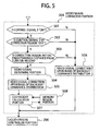
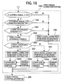
- the video signal corrector portion mentioned above being inputted with the video frame, the control signal 3, the backlight luminance distribution, and the control signal 2 of each region, from the videosignalprocessor portion mentioned above,determines on whether the control signal 3 is "ON” or “OFF” in a first determining portion 1 (501).
- a first determining portion 1 501
- the control signal 3 is "ON”
- a determining portion 2 502
- the control signal of that correction region is "OFF”
- advancing into a determining portion (503) wherein it is determined whether that correction regions lies within a predetermined distance or not, from the turn-on region.
- That determining portion 3 though it conducts the transmission factor control of the liquid crystal panel, so that the black float cannot be recognized thereon, in the region near to the turn-on region, but no control is done within the region sufficiently far from the turn-on region, and thereby having a roll of decreasing the luminance of that region.
- That predetermined distance has a value, which can be set up arbitrarily, and is indicative of a number of regions from the turn-on region up to the region where the target luminance distribution comes to "0", and in the case of Figs. 1A to 1E , it is three (3), for example.
- the video signal is determined within a video signal setup portion (504).
- the video signal to be set up within that video signal setup portion is given with the arbitrary value so as to be constant within the region, and the video signal correction is made upon basis of the backlight luminance distribution.
- the P (u, v) obtained from this relationship has such a value that the light emission of the backlight comes to be uniform when it permeates through the liquid crystal panel, and it is transmitted to a coefficient calculator portion (507).
- a coefficient value for each pixel which is determined upon basis of the position relationship between the turn-on region, is read out from a memory region portion (508) to be calculated, and thereby determining a pixel gradation value P2 (u, v) to be transmitted to the liquid crystal controller portion mentioned above.
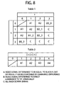
- the coefficient values to be held by the memory region portion mentioned above are shown in Fig. 8 . Every one of the coefficient values, which are held by that memory region portion, has a coefficient value corresponding to the light leakage from the neighboring region, and has a Table 1 memorizing therein a coefficient value (A), being so determined that the luminance penetrating through the liquid crystal panel comes to be equal to the black float, or that no difference of luminance can be recognized, or (B) the coefficient value determined to direct "0" of the luminance, gradually, or (C) an all black screen coefficient value, and a Table 2 memorizing therein the coefficient value if there are plural numbers of turn-on regions, having the same total value of the absolute values of "s" and "t".
- A coefficient value
- B the coefficient value determined to direct "0" of the luminance
- C an all black screen coefficient value
- the Table 1 determines the coefficient value (A), being equal to the black float or no difference of luminance can be recognized, and under the absolute value equal to or greater than "3", it determines the coefficient value (B) being determined to direct the luminance to "0" gradually or the all black screen coefficient value (C), to the correction region mentioned above.
- a coefficient value of a number "A1”, which is held by the memory region portion is called up to be calculated, and thereby obtaining the video signal of the correction region.
- a coefficient value of a number "B2-1”, which is held by the memory region portion is called up, and after being reversed up and down and left and right, it is calculated, and thereby obtaining the video signal of the correction region.
- a control signal to be transmitted to the H-driver (207) and the V-driver (208).
- a display signal upon basis of the video signal transmitted from the video signal corrector portion is produced a display signal, to be transmitted to the liquid crystal panel (209).
- a scanning signal In the V-driver is produced a scanning signal, to be transmitted to the liquid crystal panel.
- the liquid crystal panel upon driving of each scanning electrode and each data electrode, the corresponding pixel region is applied with gradation voltage corresponding to the display signal, and thereby controlling a response of the liquid crystal in that pixel region.
- the transmission method for transmitting the backlight control value of each region from the video signal processor portion to the backlight controller portion should not be limited to, in particular, but may be achieved by using a bus line for exclusive use thereof, using an interface in accordance with any one of various kinds of interface standard, or inserting the backlight control value into a blanking period of the video signal, etc., as far as a signal for designating that region and a signal for designating an intensity of light emission thereof are included therein.
- the control signal corresponding to the intensity of light emission of each backlight portion (210) is transmitted to the backlight driver portion mentioned above.
- the signal for driving the backlight may be of PWM (Pulse Width Modulation) or amplitude modulation.
- PWM Pulse Width Modulation
- a PWM frequency is constant, and a ratio between ON period and OFF period (i.e., a duty ratio) is changed depending on the intensity of light emission; thereby letting a LED driver for driving the LED to conduct the PWM control.
- the PWM frequency is higher than a frame frequency of the liquid crystal display apparatus.
- the video signal is determined to be set to the correction region.
- the embodiment 2 differs from the embodiment 1, in particular, in the operation of the control filter (302), the method for determining the backlight control value when the control signal 3 is "ON”, and the operation of the video signal corrector portion (205).
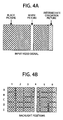
- Figs. 9A to 9C are views for showing the second embodiment of the present invention, in particular, classifying the display region (101) into three (3) kinds of regions.
- the control filter mentioned above receives the control signal 1 and the control signal 2 of each region, from the histogram detector portion (301) for each region, and it turns the control signal 3 "ON", when the control signals 1 for all regions are "ON" and also when the region, the control signal 2 of which is "ON", is included only within the region "I”.
- the backlight control value of the region, the control signal 2 of which is "OFF”, apart from the turn-on region at the predetermined distance and equal or less than the predetermined value in the amount of the leakage lights leaking from the turn-on region, is determined, so that the backlight emits the lights at the value sufficiently small ("1" by 8 bits) comparing to that of the region, the control signal 2 of which is "ON", within a limit that the target luminance distribution can be expressed by changing the transmission factor of the liquid crystal panel.
- the backlight control value of the region, the control signal 2 of which is "OFF”, is set to "0", and thereby putting out the lights.
- the correction regionmentioned above, included within the region "I", in the region, the control signal 2 of which is "OFF", is determined, by reading out the coefficient value, being determined to be equal to the black float or no luminance difference be visually recognizable thereon, from a memory region portion (1005), and calculating it within a coefficient calculator portion (1003).
- That correction region included within the region “J” is determined, by reading out the coefficient value, being determined to direct to "0" of the luminance gradually, from a memory region portion (1006), and calculating it within a coefficient calculator portion (1004). No video correction is done upon that correction region, which is included in the region "K" (1001).
- the methods for determining the numbers of regions of the region “I”, the region “J” and the region “K”, and the methods of taking the configuration of the regions are not determined or constant, but may be obtained by others than that shown in Figs. 9A to 9C .
- the region “I”, the region “J” and the region “K” there is no necessity of including all the region “I”, the region “J” and the region “K” therein, but the following combinations are possible: i.e., only the region “J” and the region “K”, only the region “I” and the region “J”, etc., for example.
- Fig. 11 is a block diagram for showing an entire circuit of the liquid crystal display apparatus, according to a third embodiment of the present invention.
- the liquid crystal display apparatus is constructed by adding a motion picture detector means (1102) to that of the embodiment 2.
- a motion picture detector means including a motion vector, representatively, and it transmits an output thereof to a video signal processor portion (1101), and that video signal processor portion changes a control method with using this output.
- the motion picture detector portion must be provided outside the video signal processor means, but may be included within the video signal processor portion.
- control filter (302) When a motion picture is detected by the motion picture detector means, the operation of the control filter (302) differs from that of the embodiment 2. Thus, the control filter changes the region "I", the region “J” and the region “K” in Figs. 9A to 9C , depending on the direction of movement of the input video signal.
- the video when detecting that such the picture or video as was mentioned above is inputted by the motion picture detector means, the video can be always determined so that no equivalence to the black float nor no difference of luminance can be recognized, visually, thereon, and it is possible to display a picture or video having the constant luminance distribution within a surface irrespective of the position information of the turn-on region, i.e., no back float can be visually recognized thereon.
- the explanation was made on the examples of using the LED as the light source, but other light source than that may be applied therein, such as, a laser diode, cold-cathode/hot-cathode fluorescence tubes (CCFL, EEFL, HCFL).
- a laser diode cold-cathode/hot-cathode fluorescence tubes (CCFL, EEFL, HCFL).
- This invention can be applied to a liquid crystal display apparatus having the backlight divided into a plural number of regions, for enabling to control them individually, such as, a liquid crystal television or a portable display, for example.
Landscapes
- Engineering & Computer Science (AREA)
- Physics & Mathematics (AREA)
- General Physics & Mathematics (AREA)
- Theoretical Computer Science (AREA)
- Computer Hardware Design (AREA)
- Liquid Crystal Display Device Control (AREA)
- Control Of Indicators Other Than Cathode Ray Tubes (AREA)
- Transforming Electric Information Into Light Information (AREA)
- Liquid Crystal (AREA)
Applications Claiming Priority (1)
| Application Number | Priority Date | Filing Date | Title |
|---|---|---|---|
| JP2009019442A JP2010175913A (ja) | 2009-01-30 | 2009-01-30 | 画像表示装置 |
Publications (2)
| Publication Number | Publication Date |
|---|---|
| EP2214154A2 true EP2214154A2 (de) | 2010-08-04 |
| EP2214154A3 EP2214154A3 (de) | 2011-02-09 |
Family
ID=42153901
Family Applications (1)
| Application Number | Title | Priority Date | Filing Date |
|---|---|---|---|
| EP09252691A Withdrawn EP2214154A3 (de) | 2009-01-30 | 2009-11-27 | Videowiedergabevorrichtung |
Country Status (4)
| Country | Link |
|---|---|
| US (1) | US20100194791A1 (de) |
| EP (1) | EP2214154A3 (de) |
| JP (1) | JP2010175913A (de) |
| CN (1) | CN101794542A (de) |
Cited By (1)
| Publication number | Priority date | Publication date | Assignee | Title |
|---|---|---|---|---|
| US10692444B2 (en) | 2018-09-24 | 2020-06-23 | Bose Corporation | Systems and methods for controlling operation of a backlight for a display panel |
Families Citing this family (31)
| Publication number | Priority date | Publication date | Assignee | Title |
|---|---|---|---|---|
| JP5650422B2 (ja) * | 2010-03-24 | 2015-01-07 | ソニー株式会社 | 液晶表示装置 |
| JP5541546B2 (ja) * | 2010-04-23 | 2014-07-09 | Necディスプレイソリューションズ株式会社 | 表示装置、表示方法およびプログラム |
| JP5337757B2 (ja) | 2010-04-28 | 2013-11-06 | 日立コンシューマエレクトロニクス株式会社 | 液晶表示装置及びバックライトの制御方法 |
| CN101950543B (zh) * | 2010-09-08 | 2012-07-04 | 青岛海信电器股份有限公司 | 动态背光调整方法及装置 |
| JP2012123100A (ja) * | 2010-12-07 | 2012-06-28 | Hitachi Consumer Electronics Co Ltd | 液晶表示装置 |
| US9142157B2 (en) * | 2011-01-20 | 2015-09-22 | Apple Inc. | Methods for enhancing longevity in electronic device displays |
| US8749473B2 (en) | 2011-03-15 | 2014-06-10 | Sharp Kabushiki Kaisha | Video display device |
| JP5452666B2 (ja) * | 2011-08-04 | 2014-03-26 | シャープ株式会社 | 映像表示装置 |
| JP6033532B2 (ja) * | 2011-08-19 | 2016-11-30 | 三菱電機株式会社 | 液晶表示装置 |
| JP6045138B2 (ja) * | 2011-11-29 | 2016-12-14 | キヤノン株式会社 | 画像表示装置及びその制御方法 |
| CN102651204B (zh) * | 2012-03-26 | 2014-12-17 | 京东方科技集团股份有限公司 | 一种区域调光显示图像的方法、装置及系统 |
| US8740061B2 (en) * | 2012-07-06 | 2014-06-03 | Hewlett-Packard Development Company, L.P. | Recording information for a web manufacturing process |
| CN103021345B (zh) * | 2012-12-18 | 2014-12-24 | 四川长虹电器股份有限公司 | 一种消除液晶屏漏光的方法 |
| CN103971624A (zh) * | 2013-01-28 | 2014-08-06 | 富泰华工业(深圳)有限公司 | 漏光检测系统及方法 |
| US9852497B2 (en) * | 2013-04-04 | 2017-12-26 | Nvidia Corporation | Per pixel mapping for image enhancement |
| US9830865B2 (en) | 2013-04-04 | 2017-11-28 | Nvidia Corporation | Regional histogramming for global approximation |
| US10019787B2 (en) | 2013-04-04 | 2018-07-10 | Nvidia Corporation | Regional dimming for power savings |
| JP6198512B2 (ja) * | 2013-08-06 | 2017-09-20 | キヤノン株式会社 | 画像表示装置、その制御方法、及び画像表示システム |
| JP2015082022A (ja) | 2013-10-22 | 2015-04-27 | 株式会社ジャパンディスプレイ | 表示装置、表示装置の駆動方法及び電子機器 |
| US10165217B2 (en) | 2014-08-28 | 2018-12-25 | Hisense Electric Co., Ltd. | Backlight source control method of display device, display device and storage medium |
| CN106611587B (zh) * | 2014-08-28 | 2019-03-15 | 青岛海信电器股份有限公司 | 进入或退出宽银幕电影显示模式时背光源控制方法及装置 |
| TWI563491B (en) * | 2014-12-30 | 2016-12-21 | Jadard Technology Inc | Image process system and method |
| CN104575406A (zh) * | 2015-02-09 | 2015-04-29 | 京东方科技集团股份有限公司 | 驱动背光板的方法及时序控制器、背光驱动板 |
| CN106157286B (zh) * | 2015-04-03 | 2020-11-17 | 研祥智能科技股份有限公司 | 图像处理方法和屏幕漏光检测方法 |
| JP5990302B2 (ja) * | 2015-05-07 | 2016-09-14 | キヤノン株式会社 | 表示制御装置及びその制御方法 |
| CN105374323B (zh) * | 2015-12-18 | 2018-02-13 | 深圳Tcl数字技术有限公司 | 点阵背光源驱动方法、装置和系统 |
| US10803828B2 (en) | 2017-02-24 | 2020-10-13 | Apple Inc. | Locally adaptive backlight control |
| TWI637384B (zh) * | 2017-11-30 | 2018-10-01 | 奇景光電股份有限公司 | 比對影像數據之運算值以檢測傳輸品質之顯示系統及方法 |
| US20200202798A1 (en) * | 2018-12-24 | 2020-06-25 | Lincoln Technology Solutions, Inc. | Video Pipeline Pixel Analysis for Full Array Local Dimming |
| JP7460913B2 (ja) * | 2021-02-26 | 2024-04-03 | 日亜化学工業株式会社 | 画像表示方法及び画像表示装置 |
| CN116129818B (zh) * | 2022-12-19 | 2024-07-23 | 厦门天马微电子有限公司 | 显示模组及其驱动方法、显示装置 |
Family Cites Families (6)
| Publication number | Priority date | Publication date | Assignee | Title |
|---|---|---|---|---|
| KR930010487B1 (ko) * | 1990-12-31 | 1993-10-25 | 삼성전자 주식회사 | 디지탈 자동 화이트 밸런스 회로 |
| US5465118A (en) * | 1993-12-17 | 1995-11-07 | International Business Machines Corporation | Luminance transition coding method for software motion video compression/decompression |
| TW200739507A (en) * | 2006-03-23 | 2007-10-16 | Toshiba Matsushita Display Tec | Liquid crystal display device |
| JP2008052259A (ja) * | 2006-07-26 | 2008-03-06 | Toshiba Matsushita Display Technology Co Ltd | 液晶表示装置 |
| JP2008176211A (ja) * | 2007-01-22 | 2008-07-31 | Hitachi Ltd | 液晶表示装置及びその輝度制御方法 |
| JP2010532491A (ja) * | 2007-07-04 | 2010-10-07 | コーニンクレッカ フィリップス エレクトロニクス エヌ ヴィ | 表示器のバックライトを駆動する方法及びシステム |
-
2009
- 2009-01-30 JP JP2009019442A patent/JP2010175913A/ja active Pending
- 2009-11-16 CN CN200910225225A patent/CN101794542A/zh active Pending
- 2009-11-27 EP EP09252691A patent/EP2214154A3/de not_active Withdrawn
- 2009-12-02 US US12/629,210 patent/US20100194791A1/en not_active Abandoned
Non-Patent Citations (1)
| Title |
|---|
| None |
Cited By (1)
| Publication number | Priority date | Publication date | Assignee | Title |
|---|---|---|---|---|
| US10692444B2 (en) | 2018-09-24 | 2020-06-23 | Bose Corporation | Systems and methods for controlling operation of a backlight for a display panel |
Also Published As
| Publication number | Publication date |
|---|---|
| CN101794542A (zh) | 2010-08-04 |
| EP2214154A3 (de) | 2011-02-09 |
| JP2010175913A (ja) | 2010-08-12 |
| US20100194791A1 (en) | 2010-08-05 |
Similar Documents
| Publication | Publication Date | Title |
|---|---|---|
| EP2214154A2 (de) | Videowiedergabevorrichtung | |
| JP5570791B2 (ja) | 表示装置駆動方法 | |
| JP5070331B2 (ja) | 照明装置およびこれを備えた表示装置 | |
| CN102483904B (zh) | 液晶显示装置、电视接收机 | |
| JP5460435B2 (ja) | 画像表示装置および画像表示装置の制御方法 | |
| EP1950731B1 (de) | Flüssigkristallanzeigeeinrichtung | |
| JP6039307B2 (ja) | 画像表示装置及びその制御方法 | |
| EP1983505B1 (de) | Flüssigkristallanzeigeeinrichtung | |
| US8451212B2 (en) | Display apparatus and control circuit of the same | |
| US8810611B2 (en) | Liquid crystal display device | |
| US20070182700A1 (en) | Image display device and image display method | |
| EP2043079A2 (de) | Videoanzeigegerät mit dynamischer Helligkeitssteuerung des Backlights | |
| JP2003140110A (ja) | 液晶表示装置とその駆動回路 | |
| CN102842288A (zh) | 具有动态亮度缩放的背光视频显示器 | |
| US12230185B2 (en) | Display apparatus and driving method thereof | |
| US20120086740A1 (en) | Liquid Crystal Display Device And Light Source Control Method | |
| US11605356B2 (en) | Driving display apparatus and method acquiring current duty to drive backlight unit based on excluding text area in input image | |
| EP2020655A1 (de) | Flüssigkristallanzeigevorrichtung und Flüssigkristallfernsehgerät | |
| US20090085862A1 (en) | Video displaying apparatus | |
| US9786216B2 (en) | Display apparatus, light-emitting device, and control method of display apparatus | |
| US20100225670A1 (en) | Display device and method of providing illumination thereto | |
| JP2009042650A (ja) | 液晶表示装置及びこれに用いる映像表示方法 | |
| EP2296137A1 (de) | Bildanzeigevorrichtung und Betriebsverfahren dafür | |
| JP2009048131A (ja) | 液晶表示装置 | |
| JP5176896B2 (ja) | 液晶表示装置 |
Legal Events
| Date | Code | Title | Description |
|---|---|---|---|
| PUAI | Public reference made under article 153(3) epc to a published international application that has entered the european phase |
Free format text: ORIGINAL CODE: 0009012 |
|
| 17P | Request for examination filed |
Effective date: 20091215 |
|
| AK | Designated contracting states |
Kind code of ref document: A2 Designated state(s): AT BE BG CH CY CZ DE DK EE ES FI FR GB GR HR HU IE IS IT LI LT LU LV MC MK MT NL NO PL PT RO SE SI SK SM TR |
|
| AX | Request for extension of the european patent |
Extension state: AL BA RS |
|
| PUAL | Search report despatched |
Free format text: ORIGINAL CODE: 0009013 |
|
| AK | Designated contracting states |
Kind code of ref document: A3 Designated state(s): AT BE BG CH CY CZ DE DK EE ES FI FR GB GR HR HU IE IS IT LI LT LU LV MC MK MT NL NO PL PT RO SE SI SK SM TR |
|
| AX | Request for extension of the european patent |
Extension state: AL BA RS |
|
| 17Q | First examination report despatched |
Effective date: 20110929 |
|
| STAA | Information on the status of an ep patent application or granted ep patent |
Free format text: STATUS: THE APPLICATION IS DEEMED TO BE WITHDRAWN |
|
| 18D | Application deemed to be withdrawn |
Effective date: 20130601 |