EP2215397B1 - Tete de trepied - Google Patents
Tete de trepied Download PDFInfo
- Publication number
- EP2215397B1 EP2215397B1 EP08844824A EP08844824A EP2215397B1 EP 2215397 B1 EP2215397 B1 EP 2215397B1 EP 08844824 A EP08844824 A EP 08844824A EP 08844824 A EP08844824 A EP 08844824A EP 2215397 B1 EP2215397 B1 EP 2215397B1
- Authority
- EP
- European Patent Office
- Prior art keywords
- bearing housing
- bearing
- tripod head
- clamping device
- clamping ring
- Prior art date
- Legal status (The legal status is an assumption and is not a legal conclusion. Google has not performed a legal analysis and makes no representation as to the accuracy of the status listed.)
- Not-in-force
Links
- 230000003287 optical effect Effects 0.000 claims abstract description 9
- 230000000295 complement effect Effects 0.000 claims abstract description 5
- 230000003313 weakening effect Effects 0.000 claims description 4
- 210000000056 organ Anatomy 0.000 description 5
- 210000003746 feather Anatomy 0.000 description 3
- 238000005553 drilling Methods 0.000 description 2
- 230000035515 penetration Effects 0.000 description 2
- 230000005540 biological transmission Effects 0.000 description 1
- 238000011109 contamination Methods 0.000 description 1
- 230000001419 dependent effect Effects 0.000 description 1
- 238000006073 displacement reaction Methods 0.000 description 1
- ZINJLDJMHCUBIP-UHFFFAOYSA-N ethametsulfuron-methyl Chemical compound CCOC1=NC(NC)=NC(NC(=O)NS(=O)(=O)C=2C(=CC=CC=2)C(=O)OC)=N1 ZINJLDJMHCUBIP-UHFFFAOYSA-N 0.000 description 1
- 230000005283 ground state Effects 0.000 description 1
- 230000037431 insertion Effects 0.000 description 1
- 238000003780 insertion Methods 0.000 description 1
- 230000003993 interaction Effects 0.000 description 1
- 230000003068 static effect Effects 0.000 description 1
Images

Classifications
-
- F—MECHANICAL ENGINEERING; LIGHTING; HEATING; WEAPONS; BLASTING
- F16—ENGINEERING ELEMENTS AND UNITS; GENERAL MEASURES FOR PRODUCING AND MAINTAINING EFFECTIVE FUNCTIONING OF MACHINES OR INSTALLATIONS; THERMAL INSULATION IN GENERAL
- F16M—FRAMES, CASINGS OR BEDS OF ENGINES, MACHINES OR APPARATUS, NOT SPECIFIC TO ENGINES, MACHINES OR APPARATUS PROVIDED FOR ELSEWHERE; STANDS; SUPPORTS
- F16M11/00—Stands or trestles as supports for apparatus or articles placed thereon ; Stands for scientific apparatus such as gravitational force meters
- F16M11/02—Heads
- F16M11/04—Means for attachment of apparatus; Means allowing adjustment of the apparatus relatively to the stand
- F16M11/06—Means for attachment of apparatus; Means allowing adjustment of the apparatus relatively to the stand allowing pivoting
- F16M11/12—Means for attachment of apparatus; Means allowing adjustment of the apparatus relatively to the stand allowing pivoting in more than one direction
- F16M11/14—Means for attachment of apparatus; Means allowing adjustment of the apparatus relatively to the stand allowing pivoting in more than one direction with ball-joint
-
- F—MECHANICAL ENGINEERING; LIGHTING; HEATING; WEAPONS; BLASTING
- F16—ENGINEERING ELEMENTS AND UNITS; GENERAL MEASURES FOR PRODUCING AND MAINTAINING EFFECTIVE FUNCTIONING OF MACHINES OR INSTALLATIONS; THERMAL INSULATION IN GENERAL
- F16C—SHAFTS; FLEXIBLE SHAFTS; ELEMENTS OR CRANKSHAFT MECHANISMS; ROTARY BODIES OTHER THAN GEARING ELEMENTS; BEARINGS
- F16C11/00—Pivots; Pivotal connections
- F16C11/04—Pivotal connections
- F16C11/10—Arrangements for locking
- F16C11/103—Arrangements for locking frictionally clamped
- F16C11/106—Arrangements for locking frictionally clamped for ball joints
-
- F—MECHANICAL ENGINEERING; LIGHTING; HEATING; WEAPONS; BLASTING
- F16—ENGINEERING ELEMENTS AND UNITS; GENERAL MEASURES FOR PRODUCING AND MAINTAINING EFFECTIVE FUNCTIONING OF MACHINES OR INSTALLATIONS; THERMAL INSULATION IN GENERAL
- F16M—FRAMES, CASINGS OR BEDS OF ENGINES, MACHINES OR APPARATUS, NOT SPECIFIC TO ENGINES, MACHINES OR APPARATUS PROVIDED FOR ELSEWHERE; STANDS; SUPPORTS
- F16M11/00—Stands or trestles as supports for apparatus or articles placed thereon ; Stands for scientific apparatus such as gravitational force meters
- F16M11/02—Heads
- F16M11/04—Means for attachment of apparatus; Means allowing adjustment of the apparatus relatively to the stand
- F16M11/041—Allowing quick release of the apparatus
-
- F—MECHANICAL ENGINEERING; LIGHTING; HEATING; WEAPONS; BLASTING
- F16—ENGINEERING ELEMENTS AND UNITS; GENERAL MEASURES FOR PRODUCING AND MAINTAINING EFFECTIVE FUNCTIONING OF MACHINES OR INSTALLATIONS; THERMAL INSULATION IN GENERAL
- F16M—FRAMES, CASINGS OR BEDS OF ENGINES, MACHINES OR APPARATUS, NOT SPECIFIC TO ENGINES, MACHINES OR APPARATUS PROVIDED FOR ELSEWHERE; STANDS; SUPPORTS
- F16M11/00—Stands or trestles as supports for apparatus or articles placed thereon ; Stands for scientific apparatus such as gravitational force meters
- F16M11/02—Heads
- F16M11/16—Details concerning attachment of head-supporting legs, with or without actuation of locking members thereof
-
- G—PHYSICS
- G03—PHOTOGRAPHY; CINEMATOGRAPHY; ANALOGOUS TECHNIQUES USING WAVES OTHER THAN OPTICAL WAVES; ELECTROGRAPHY; HOLOGRAPHY
- G03B—APPARATUS OR ARRANGEMENTS FOR TAKING PHOTOGRAPHS OR FOR PROJECTING OR VIEWING THEM; APPARATUS OR ARRANGEMENTS EMPLOYING ANALOGOUS TECHNIQUES USING WAVES OTHER THAN OPTICAL WAVES; ACCESSORIES THEREFOR
- G03B17/00—Details of cameras or camera bodies; Accessories therefor
- G03B17/56—Accessories
- G03B17/566—Accessory clips, holders, shoes to attach accessories to camera
-
- Y—GENERAL TAGGING OF NEW TECHNOLOGICAL DEVELOPMENTS; GENERAL TAGGING OF CROSS-SECTIONAL TECHNOLOGIES SPANNING OVER SEVERAL SECTIONS OF THE IPC; TECHNICAL SUBJECTS COVERED BY FORMER USPC CROSS-REFERENCE ART COLLECTIONS [XRACs] AND DIGESTS
- Y10—TECHNICAL SUBJECTS COVERED BY FORMER USPC
- Y10T—TECHNICAL SUBJECTS COVERED BY FORMER US CLASSIFICATION
- Y10T403/00—Joints and connections
- Y10T403/32—Articulated members
- Y10T403/32606—Pivoted
- Y10T403/32631—Universal ball and socket
- Y10T403/32737—Universal ball and socket including liner, shim, or discrete seat
- Y10T403/32745—Spring acts through wedging surfaces
Definitions
- the invention relates to a tripod head with a tilting device with a ball joint, which has a pivotally mounted in a bearing housing ball joint, which is mounted between two plain bearings in the bearing housing, one of which sliding bearing is axially slidably mounted in the direction of spacing of the sliding bearing in the bearing housing wherein the ball joint is disposed between terminals located at opposite ends of the tilting device, one of which is connected or connectable to a camera, a spotting scope, a pair of binoculars or the like optical device or a holding device and the other with at least one tripod leg or the like holder.
- Such a tilt unit is for example from the German patent application 10 2006 001 580 A1 known.
- the axially displaceable sliding bearing is supported but only at one point by a conical pin. Due to the small contact surface, the force with which the sliding bearing can be pressed against the ball joint, correspondingly low. This results in a total of only low carrying capacity of the entire tripod head.
- a tilting moment through which the sliding bearing can tilt in the bearing housing and damage to the bearing housing or plain bearing can occur as a result.
- a tripod head which has a cylindrical bearing housing in the housing interior, a joint ball is rotatably and pivotally mounted.
- a bearing element is axially displaceable and rotatably arranged, which has a voltage applied to the periphery of the ball joint sliding surface.
- the bearing element is associated with a support which is in operative connection with an actuating device in such a way that the bearing element can be displaced against the joint ball in order to achieve the clamping action.
- This adjusting device has circular-arc-shaped organs, which are connected to each other via an adjusting screw, which adjusting screw in the region of the organs has opposite threaded portions.
- a tripod head which has a removable disk to which a camera, binoculars, a spotting scope or the like optical device can be attached.
- This removable disk is assigned a base, which can be attached to a tripod or the like carrying frame.
- a dovetail guide is provided with a guide rail for slidably supporting the removable plate and a relative to the base relatively movable clamping device for fixing the removable plate in the guide rail.
- the clamping device may be configured as a pivot lever which is rotatable between an open position releasing the removable plate for removal and a closed position, in which closed position the removable plate is slidably received in the guide.
- an expandable at a gap clamping ring is arranged with a tapered to the longitudinal center plane in the direction of the ball joint inclined surface and the inclined surface cooperates with a complementary shaped counter-bevel on the axially displaceable sliding bearing.
- the clamping ring is fixed on the other side by a snap ring or the like means in its position, so that no other evasive movement is possible.
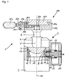
- the Fig. 1 shows a generally designated 1 tripod head with a tilting device 2 and a holder 100 attached thereto with a quick release plate 101st
- the tilting device 2 has an approximately cylindrical bearing housing 3, which is designed as a hollow cylinder. At its upper end 4, a non-visible in the figure, right-angle flange is arranged, which forms an upper bearing shell for a ball joint. On the flange a likewise not visible by the partial sectional view slide bearing with a preferably spherical sliding surface is arranged, which cooperates with a joint ball 5.
- the ball joint 5 has in the axial direction of the bearing housing 3 a straight extension 6 with a thread on which a payload can be attached.
- a further, axially displaceable slide bearing 7 is arranged with a spherical, adapted to the ball 5 bearing surface 8.
- a clamping ring 9 connects. The entire assembly is supported by an abutment 10 down and thus held in the bearing housing 3.
- the clamping ring 9 has a reduced compared to the inner diameter of the bearing housing 3 circumference. Furthermore, the clamping ring 9 has at its upper edge to the longitudinal central axis 11 in the direction of the ball joint 5 tapered inclined surface 12 which cooperates with a complementary shaped counter-bevel 13 on the underside of the sliding bearing 7.
- a threaded bore 14 is arranged approximately at the height of the clamping ring 9, in which a threaded bolt 15 can be moved transversely to the longitudinal central axis 11 of the bearing housing 3.
- a Handwheel 17 arranged for manual operation.
- the inner end 18 is formed approximately tapered and engages in an axial gap 19 in the clamping ring 9 a.
- the gap 19 acts together with the conical end 18 of the threaded bolt 15 such that with increasing penetration of the threaded bolt 15 in the gap 19, the clamping ring 9 is widened.
- the clamping ring 9 has a material weakening 20 to allow for easier expansion.
- the clamping ring 9 acts uniformly over the entire circumference of the sliding bearing 7, a very homogeneous force is given. There are no turning or tilting moments on the sliding bearing 7 in this clamping operation, so that damage to the bearing housing 3 or the sliding bearing 7 are practically excluded by tilting. In addition, by the full support of the sliding bearing 7, the carrying capacity of the tilting device 2 is substantially higher than in the prior art.
- the threaded bolt 15 is to protect against contamination of an integrally formed on the bearing housing 3 cylindrical socket 21 surrounded, wherein in a groove on the threaded bolt 15, an O-ring 22 is inserted, on the other hand rests against the inner wall of the sleeve 21.
- the handwheel 17 at the end of the threaded bolt 15 has a direction towards the bearing housing 3 projecting edge 23 which engages over the sleeve 21 and a penetration of dirt to the sleeve 21 difficult.
- Fig. 2 It can be seen that the clamping ring 9 rests in the relaxed state only in the region of the material weakening 20 on the bearing housing inner wall so that there is enough space for expansion available.
- the gap 19 in the clamping ring 9 is approximately as wide as the material thickness in the ground state.
- the abutment 10 is formed in the embodiment by a securing ring, which is arranged in a circumferential inner groove in the bearing housing below the clamping ring 9.
- the other two molded sockets 24, 25 are provided for other functions, which are not the subject of the invention.
- a holding device 100 which essentially has a base 102 with a central threaded bore 127 into which the threaded extension 6 of the ball joint 5 is screwed.
- the base 102 has a receptacle designed as a dovetail guide for a removable plate 101.
- the replacement plate 101 is attached to an optical instrument to be connected to the base 102.
- a guide rail 104 of the dovetail guide is integrally formed on a longitudinal side 103.
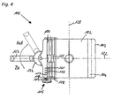
- an approximately cylindrical groove 106 is arranged, in which a cylindrical clamping device 107 is inserted. So that the clamping device 107 is not in the longitudinal direction 128 from the groove 106 may fall, at both ends of the clamping device 107 in each case a projecting beyond the groove 106 collar 108 is formed.
- the clamping device 107 has a longitudinally 128 continuous segmental opening 109, which forms the counter-guide of the dovetail guide.
- the clamping device 107 is rotatably mounted in the groove 106 and has essentially two positions.
- a second, open position of the clamping device 107 in which the removable plate 101 can be removed upwards or inserted from above, is in the Fig. 3 shown.
- the removable disk 101 is first hooked on the fixed guide rail 104 as shown, and then lowered.
- this rotates by the contact pressure in the closed position.
- the latching device 110 consists of a spring 111 and a detent ball 112, which is arranged approximately centrally in a bore 113 in the base 102 of the clamping device 107 and cooperates with a spherical recess 114 in the clamping device 107. By the latching device 110, the open position of the clamping device 107 receives a defined position.
- the clamping device 107 is acted upon by the detent ball 112, which is pressed by the spring 111 against the circumference of the clamping device 107.
- the preferably spherical or otherwise spherical recess 114 is provided, in which the detent ball 112 can engage under the transmission of torque and twisting of the clamping device 107 in the removal position.
- a fuse 115 is further arranged, which prevents unintentional rotation of the clamping device 107 and thereby releasing the removable plate 101.
- a spring pin 116 is arranged, which has three different diameters 117, 118, 119 and arranged on the collar 108 of the clamping device 107 has a notch. In the closed position of the clamping device 107, the notch rests against the central diameter portion 118 of the spring pin 116 and thus blocks a rotational movement of the clamping device 107.
- the larger diameter 117 lying further inside is located in the longitudinal direction 128 on the collar 108 and prevented in both Positions of the clamping device 107 falling out of the spring pin 116 from the bore 121.
- the spring pin 116 To open the fuse 115, the spring pin 116 must now be pressed against the spring 120 inward, so that the part 119 with the smallest diameter facing the collar circumference and the engagement of the notch is canceled and the clamping device 107 is released for rotation.
- the clamping device 107 is rotated in the open position.
- the clamping device 107 can additionally be moved in the transverse direction 122.
- the groove 106 in the transverse direction 122 of the base 102 is slightly larger than the diameter of the clamping device 107, so that a linear movement is possible.
- an operating element 123 is provided, which is rotatably mounted on the base 102 and has an eccentric wheel 124, which cooperates with the clamping device 107. A rotational movement of the operating element 123 is thereby converted into a transverse movement of the clamping device 107.
- the clamping device 107 in the attack region of the operating element on a circumferential spherical groove 125.
- a likewise spherical groove 126 is arranged, which is deeper according to the eccentricity in the course of the circumference and cooperates with the groove 125 in the clamping device 107.
- This spherical groove 126 is necessary because the clamping device 107 is additionally rotatable.
- the holding device 100 with the rotatable clamping device 107 allows easy insertion of heavy or bulky optical instruments on the tripod head 1. In this case, the user does not have to stoop or awkward feel the leadership in the fixture 100. Furthermore, the ball head 2 according to the invention allows the safe recording and locking of the heavy instruments, since the carrying capacity is increased accordingly by the uniform clamping of the ball joint 5 over the prior art.
Landscapes
- Engineering & Computer Science (AREA)
- General Engineering & Computer Science (AREA)
- Mechanical Engineering (AREA)
- Physics & Mathematics (AREA)
- General Physics & Mathematics (AREA)
- Accessories Of Cameras (AREA)
- Pivots And Pivotal Connections (AREA)
Claims (3)
- Tête de trépied dotée d'un dispositif d'inclinaison (100) avec une articulation à rotule, qui comprend une rotule articulée (5) logée à pivotement dans un boîtier de palier (3), laquelle est montée entre deux paliers lisses dans le boîtier de palier (3), dont l'un des paliers lisses (7) est monté dans le boîtier de palier (3) de façon coulissante axialement dans le sens d'espacement des paliers lisses (7), l'articulation à rotule étant disposée entre des points de branchement se trouvant sur des extrémités opposées les unes aux autres du dispositif d'inclinaison (100), points dont l'un est relié ou peut être relié à une caméra, une longue vue, des jumelles ou un appareil optique similaire ou un dispositif de maintien et l'autre est relié ou peut être relié à au moins une branche de trépied ou un support similaire, caractérisée en ce qu'une bague de serrage (9) pouvant s'élargir sur une fente avec une surface inclinée (12) se rétrécissant par rapport au plan médian longitudinal en direction de la rotule articulée (5) est disposée dans le boîtier de palier (3) et la surface inclinée (12) coopère avec un contre-chanfrein (13) formé de façon complémentaire sur le palier lisse (7) coulissant axialement.
- Tête de trépied selon la revendication 1, caractérisée en ce que la bague de serrage (9) présente un affaiblissement de matière (20) à peu près en face de la fente (19).
- Tête de trépied selon la revendication 1 ou 2, caractérisée en ce qu'il est prévu un élément de
sollicitation (17) qui présente une extrémité (18) conçue à peu près en forme de cône, s'engageant dans la fente (19) de la bague de serrage (9), et qui est monté à rotation dans un trou fileté (14) du boîtier de palier (3).
Priority Applications (1)
| Application Number | Priority Date | Filing Date | Title |
|---|---|---|---|
| EP10013252.1A EP2273178B1 (fr) | 2007-10-30 | 2008-10-21 | Tête de trépied |
Applications Claiming Priority (2)
| Application Number | Priority Date | Filing Date | Title |
|---|---|---|---|
| DE102007052039A DE102007052039B3 (de) | 2007-10-30 | 2007-10-30 | Stativkopf |
| PCT/EP2008/008892 WO2009056249A1 (fr) | 2007-10-30 | 2008-10-21 | Tête de trépied |
Related Child Applications (2)
| Application Number | Title | Priority Date | Filing Date |
|---|---|---|---|
| EP10013252.1A Division EP2273178B1 (fr) | 2007-10-30 | 2008-10-21 | Tête de trépied |
| EP10013252.1 Division-Into | 2010-10-02 |
Publications (2)
| Publication Number | Publication Date |
|---|---|
| EP2215397A1 EP2215397A1 (fr) | 2010-08-11 |
| EP2215397B1 true EP2215397B1 (fr) | 2011-05-11 |
Family
ID=40276154
Family Applications (2)
| Application Number | Title | Priority Date | Filing Date |
|---|---|---|---|
| EP10013252.1A Not-in-force EP2273178B1 (fr) | 2007-10-30 | 2008-10-21 | Tête de trépied |
| EP08844824A Not-in-force EP2215397B1 (fr) | 2007-10-30 | 2008-10-21 | Tete de trepied |
Family Applications Before (1)
| Application Number | Title | Priority Date | Filing Date |
|---|---|---|---|
| EP10013252.1A Not-in-force EP2273178B1 (fr) | 2007-10-30 | 2008-10-21 | Tête de trépied |
Country Status (8)
| Country | Link |
|---|---|
| US (1) | US8282055B2 (fr) |
| EP (2) | EP2273178B1 (fr) |
| JP (1) | JP2011501081A (fr) |
| KR (1) | KR20100096069A (fr) |
| CN (1) | CN101861491B (fr) |
| AT (1) | ATE509227T1 (fr) |
| DE (1) | DE102007052039B3 (fr) |
| WO (1) | WO2009056249A1 (fr) |
Families Citing this family (33)
| Publication number | Priority date | Publication date | Assignee | Title |
|---|---|---|---|---|
| US7658556B2 (en) * | 2005-01-07 | 2010-02-09 | Joseph Johnson | Panoramic camera mount |
| DE102008061980B4 (de) * | 2008-12-12 | 2012-11-22 | Cullmann Foto-Audio-Video Gmbh | Schnellspannvorrichtung |
| JP2012522277A (ja) * | 2009-03-30 | 2012-09-20 | ジーイー・ヘルスケア・バイオサイエンス・アクチボラグ | ホログラフィック回折格子のホルダ |
| DE102010024657B4 (de) * | 2010-06-22 | 2015-02-26 | FLM GMBH FOTO-, LICHT- UND MEßTECHNISCHES ZUBEHÖR | Stativkopf |
| US8827219B2 (en) * | 2011-12-09 | 2014-09-09 | Kessler Crane, Inc. | Quick release plate |
| ITPD20120034A1 (it) * | 2012-02-10 | 2013-08-11 | Manfrotto Lino & C Spa | Sistema di attacco per apparecchiature video-fotografiche su una testa di supporto |
| US8910914B2 (en) * | 2012-04-04 | 2014-12-16 | Audix Corporation | Mount for electronics equipment |
| KR101366004B1 (ko) * | 2012-09-04 | 2014-02-21 | 주식회사 포토클램인터내셔날 | 퀵슈에 양면 슬라이딩 회전 구조를 갖는 카메라 결착구 |
| US9070007B2 (en) * | 2013-01-11 | 2015-06-30 | Datalogic ADC, Inc. | Adjustable data reader with pivot mount |
| EP3060432B1 (fr) | 2013-07-26 | 2017-08-30 | Thule Sweden AB | Élément d'ancrage sur porte-charge pour essieu traversant de vélo |
| TWI492030B (zh) * | 2014-01-08 | 2015-07-11 | Quanta Comp Inc | 電子裝置 |
| CN104089160B (zh) * | 2014-07-11 | 2017-01-18 | 肖红 | 球形云台及其快装结构 |
| CN104633251B (zh) * | 2015-02-10 | 2017-03-15 | 无锡智能自控工程股份有限公司 | 采用偏心轮离合装置的外挂式手轮机构 |
| CN105935008B (zh) * | 2015-03-31 | 2018-02-02 | 深圳市大疆灵眸科技有限公司 | 固定结构及使用该固定结构的云台 |
| KR101722324B1 (ko) * | 2015-08-07 | 2017-04-04 | 이해심 | 멀티 퀵슈 |
| US20170187980A1 (en) * | 2015-12-23 | 2017-06-29 | Shenzhen China Star Optoelectronics Technology Co., Ltd. | Curved television and fixed base thereof |
| CN105904322B (zh) * | 2016-06-12 | 2018-08-24 | 西北工业大学 | 一种用于机器人末端的柔性打磨角磨机装置 |
| US11061302B2 (en) * | 2017-04-21 | 2021-07-13 | Syrp Limited | Quick release camera mount |
| US10364935B2 (en) * | 2017-10-25 | 2019-07-30 | Lumiquest Ventures Llc | Photographic mount |
| WO2019178849A1 (fr) * | 2018-03-23 | 2019-09-26 | 深圳市大疆创新科技有限公司 | Structure de désassemblage rapide de poignée et dispositif photographique |
| US20200062057A1 (en) * | 2018-08-21 | 2020-02-27 | GM Global Technology Operations LLC | Ball and socket assembly with clip retention system |
| US11457129B2 (en) * | 2018-09-21 | 2022-09-27 | Videotec S.P.A. | Damage resistant rotatable video camera assembly |
| USD894999S1 (en) * | 2018-10-12 | 2020-09-01 | Colorado Tripod Company | Tripod head |
| US11339916B2 (en) | 2019-10-25 | 2022-05-24 | Cade Smith | Tripod |
| CN112824011A (zh) * | 2019-11-21 | 2021-05-21 | 成都飞机工业(集团)有限责任公司 | 一种万向球芯锁紧机构 |
| CN215111699U (zh) * | 2021-01-29 | 2021-12-10 | 昆山蒲公英智能科技有限公司 | 一种快速连接机构 |
| CN116293223A (zh) * | 2021-12-20 | 2023-06-23 | 深圳市马小路科技有限公司 | 一种快拆装置 |
| CN115264296A (zh) * | 2022-08-02 | 2022-11-01 | 深圳市优至胜科技有限公司 | 摄影安装结构和支撑装置 |
| CN115773432B (zh) * | 2022-11-16 | 2025-10-17 | 黑琵科技(深圳)有限公司 | 一种转动维度可切换的球形云台 |
| CN219531815U (zh) * | 2023-02-16 | 2023-08-15 | 叶小惠 | 万向球头控制机构及支架 |
| CN117212648A (zh) * | 2023-10-30 | 2023-12-12 | 东莞市抹茶网络科技有限公司 | 支撑脚架 |
| CN117346032A (zh) * | 2023-11-09 | 2024-01-05 | 梁小映 | 一种磁吸球形云台及三脚架云台组件 |
| CN118009158A (zh) * | 2024-01-11 | 2024-05-10 | 中山大山摄影器材有限公司 | 快速拆装的摄影器材固定装置 |
Family Cites Families (14)
| Publication number | Priority date | Publication date | Assignee | Title |
|---|---|---|---|---|
| US3612462A (en) | 1969-08-26 | 1971-10-12 | Quick Set Inc | Instrument mount assembly |
| DE2048592A1 (de) * | 1970-06-25 | 1972-02-03 | Slick Tripod Co Ltd | Kameralagerungs oder Befestigungskopf |
| DE2747677A1 (de) * | 1977-10-25 | 1979-04-26 | Sachtler Filmtech Geraete | Zwischenplatte zum verbinden eines statives mit einem geraet |
| DE19839461C1 (de) * | 1998-08-29 | 1999-11-04 | Flm Gmbh Foto Licht Und Mestec | Stativkopf |
| FR2799807B1 (fr) | 1999-10-14 | 2002-03-08 | Gitzo Holding | Dispositif de verrouillage d'une rotule |
| DE50209654D1 (de) * | 2002-05-23 | 2007-04-19 | Swarovski Optik Kg | Stativkopf |
| US7621492B2 (en) * | 2002-12-18 | 2009-11-24 | Omps Justin T | Magnetic mounting assembly |
| DE50312154D1 (de) * | 2003-05-01 | 2010-01-07 | Philippe Vogt | Stativkopf |
| US6773172B1 (en) * | 2003-08-20 | 2004-08-10 | Joseph M. Johnson | Quick-release clamp for photographic equipment |
| US7490429B2 (en) * | 2003-12-02 | 2009-02-17 | Grip Pod Systems, L.L.C. | Vertical fore grip with bipod |
| US7185862B1 (en) * | 2005-10-04 | 2007-03-06 | Jen Yu Yang | Mounting platform assembly for a stand device |
| US7572074B2 (en) | 2005-12-28 | 2009-08-11 | Panasonic Corporation | Camera mounting device |
| JP4928899B2 (ja) | 2006-01-10 | 2012-05-09 | Hoya株式会社 | 内視鏡の可撓管 |
| DE102006001580B3 (de) * | 2006-01-12 | 2007-08-02 | FLM GMBH FOTO-, LICHT- UND MEßTECHNISCHES ZUBEHÖR | Stativkopf |
-
2007
- 2007-10-30 DE DE102007052039A patent/DE102007052039B3/de not_active Withdrawn - After Issue
-
2008
- 2008-10-21 JP JP2010531445A patent/JP2011501081A/ja active Pending
- 2008-10-21 US US12/740,225 patent/US8282055B2/en not_active Expired - Fee Related
- 2008-10-21 KR KR1020107009660A patent/KR20100096069A/ko not_active Withdrawn
- 2008-10-21 AT AT08844824T patent/ATE509227T1/de active
- 2008-10-21 EP EP10013252.1A patent/EP2273178B1/fr not_active Not-in-force
- 2008-10-21 WO PCT/EP2008/008892 patent/WO2009056249A1/fr not_active Ceased
- 2008-10-21 EP EP08844824A patent/EP2215397B1/fr not_active Not-in-force
- 2008-10-21 CN CN200880114112.2A patent/CN101861491B/zh not_active Expired - Fee Related
Also Published As
| Publication number | Publication date |
|---|---|
| EP2273178B1 (fr) | 2014-07-02 |
| DE102007052039B3 (de) | 2009-06-10 |
| CN101861491A (zh) | 2010-10-13 |
| CN101861491B (zh) | 2014-01-15 |
| EP2215397A1 (fr) | 2010-08-11 |
| ATE509227T1 (de) | 2011-05-15 |
| WO2009056249A1 (fr) | 2009-05-07 |
| EP2273178A1 (fr) | 2011-01-12 |
| US20100264282A1 (en) | 2010-10-21 |
| JP2011501081A (ja) | 2011-01-06 |
| US8282055B2 (en) | 2012-10-09 |
| KR20100096069A (ko) | 2010-09-01 |
Similar Documents
| Publication | Publication Date | Title |
|---|---|---|
| EP2215397B1 (fr) | Tete de trepied | |
| DE60128109T2 (de) | Vorrichtung zum fixieren von teleskopisch zusammenwirkenden elementen | |
| DE19839461C1 (de) | Stativkopf | |
| EP0265378A1 (fr) | Instrument à main avec porte-outil | |
| CH655038A5 (de) | Bohrhammer fuer bohr- und schlagbohrbetrieb. | |
| DE3437300A1 (de) | Konzepthalter zur anwendung an schreib-, zeichen-, bildschirmarbeitsplaetzen u.dgl. | |
| WO2016020028A1 (fr) | Boulon pour serrer des pièces placées l'une contre l'autre | |
| EP3064823B1 (fr) | Dispositif de serrage rapide pour le logement à fermeture automatique d'un pendant | |
| EP2997868B1 (fr) | Dispositif de fixation pour un couvercle de WC et un siège de WC sur une cuvette en céramique | |
| EP3805576A2 (fr) | Couplage | |
| EP3807012B1 (fr) | Centrifugeuse | |
| CH696571A5 (de) | Gelenkanordnung für Kabeldurchführung. | |
| DE10316190A1 (de) | Klemmvorrichtung zur Lagefixierung einer Lenksäule | |
| EP1034847A2 (fr) | Distributeur à cartouche avec dispositif de fixation de cartouche | |
| DE102012220651B4 (de) | Endoskop-Zwischenstück | |
| DE19941424C2 (de) | Vorrichtung zum Aufspannen eines Werkstückes | |
| WO2010127905A2 (fr) | Triangle intermédiaire | |
| DE102006001580B3 (de) | Stativkopf | |
| DE102012107943A1 (de) | Universalabzieher für Kugelgelenke | |
| DE2756043B2 (de) | Schwenkvorrichtung | |
| DE202007003822U1 (de) | Friktionsbremse und Stativ mit einer derartigen Bremse | |
| EP0271729A2 (fr) | Support à bras pivotant autour d'un axe et compensation des masses | |
| DE202005000397U1 (de) | Universalhalter | |
| DE19735331A1 (de) | Vorrichtung zur Aufnahme von Gegenständen | |
| DE202014000478U1 (de) | Schnellspannmutter |
Legal Events
| Date | Code | Title | Description |
|---|---|---|---|
| PUAI | Public reference made under article 153(3) epc to a published international application that has entered the european phase |
Free format text: ORIGINAL CODE: 0009012 |
|
| 17P | Request for examination filed |
Effective date: 20100531 |
|
| AK | Designated contracting states |
Kind code of ref document: A1 Designated state(s): AT BE BG CH CY CZ DE DK EE ES FI FR GB GR HR HU IE IS IT LI LT LU LV MC MT NL NO PL PT RO SE SI SK TR |
|
| AX | Request for extension of the european patent |
Extension state: AL BA MK RS |
|
| GRAP | Despatch of communication of intention to grant a patent |
Free format text: ORIGINAL CODE: EPIDOSNIGR1 |
|
| DAX | Request for extension of the european patent (deleted) | ||
| GRAS | Grant fee paid |
Free format text: ORIGINAL CODE: EPIDOSNIGR3 |
|
| GRAA | (expected) grant |
Free format text: ORIGINAL CODE: 0009210 |
|
| AK | Designated contracting states |
Kind code of ref document: B1 Designated state(s): AT BE BG CH CY CZ DE DK EE ES FI FR GB GR HR HU IE IS IT LI LT LU LV MC MT NL NO PL PT RO SE SI SK TR |
|
| REG | Reference to a national code |
Ref country code: GB Ref legal event code: FG4D Free format text: NOT ENGLISH |
|
| REG | Reference to a national code |
Ref country code: CH Ref legal event code: EP |
|
| REG | Reference to a national code |
Ref country code: IE Ref legal event code: FG4D |
|
| REG | Reference to a national code |
Ref country code: DE Ref legal event code: R096 Ref document number: 502008003534 Country of ref document: DE Effective date: 20110622 |
|
| REG | Reference to a national code |
Ref country code: NL Ref legal event code: VDEP Effective date: 20110511 |
|
| PG25 | Lapsed in a contracting state [announced via postgrant information from national office to epo] |
Ref country code: NO Free format text: LAPSE BECAUSE OF FAILURE TO SUBMIT A TRANSLATION OF THE DESCRIPTION OR TO PAY THE FEE WITHIN THE PRESCRIBED TIME-LIMIT Effective date: 20110811 Ref country code: SE Free format text: LAPSE BECAUSE OF FAILURE TO SUBMIT A TRANSLATION OF THE DESCRIPTION OR TO PAY THE FEE WITHIN THE PRESCRIBED TIME-LIMIT Effective date: 20110511 Ref country code: LT Free format text: LAPSE BECAUSE OF FAILURE TO SUBMIT A TRANSLATION OF THE DESCRIPTION OR TO PAY THE FEE WITHIN THE PRESCRIBED TIME-LIMIT Effective date: 20110511 Ref country code: PT Free format text: LAPSE BECAUSE OF FAILURE TO SUBMIT A TRANSLATION OF THE DESCRIPTION OR TO PAY THE FEE WITHIN THE PRESCRIBED TIME-LIMIT Effective date: 20110912 |
|
| PG25 | Lapsed in a contracting state [announced via postgrant information from national office to epo] |
Ref country code: FI Free format text: LAPSE BECAUSE OF FAILURE TO SUBMIT A TRANSLATION OF THE DESCRIPTION OR TO PAY THE FEE WITHIN THE PRESCRIBED TIME-LIMIT Effective date: 20110511 Ref country code: CY Free format text: LAPSE BECAUSE OF FAILURE TO SUBMIT A TRANSLATION OF THE DESCRIPTION OR TO PAY THE FEE WITHIN THE PRESCRIBED TIME-LIMIT Effective date: 20110511 Ref country code: GR Free format text: LAPSE BECAUSE OF FAILURE TO SUBMIT A TRANSLATION OF THE DESCRIPTION OR TO PAY THE FEE WITHIN THE PRESCRIBED TIME-LIMIT Effective date: 20110812 Ref country code: IS Free format text: LAPSE BECAUSE OF FAILURE TO SUBMIT A TRANSLATION OF THE DESCRIPTION OR TO PAY THE FEE WITHIN THE PRESCRIBED TIME-LIMIT Effective date: 20110911 Ref country code: SI Free format text: LAPSE BECAUSE OF FAILURE TO SUBMIT A TRANSLATION OF THE DESCRIPTION OR TO PAY THE FEE WITHIN THE PRESCRIBED TIME-LIMIT Effective date: 20110511 Ref country code: ES Free format text: LAPSE BECAUSE OF FAILURE TO SUBMIT A TRANSLATION OF THE DESCRIPTION OR TO PAY THE FEE WITHIN THE PRESCRIBED TIME-LIMIT Effective date: 20110822 Ref country code: LV Free format text: LAPSE BECAUSE OF FAILURE TO SUBMIT A TRANSLATION OF THE DESCRIPTION OR TO PAY THE FEE WITHIN THE PRESCRIBED TIME-LIMIT Effective date: 20110511 |
|
| REG | Reference to a national code |
Ref country code: IE Ref legal event code: FD4D |
|
| PG25 | Lapsed in a contracting state [announced via postgrant information from national office to epo] |
Ref country code: NL Free format text: LAPSE BECAUSE OF FAILURE TO SUBMIT A TRANSLATION OF THE DESCRIPTION OR TO PAY THE FEE WITHIN THE PRESCRIBED TIME-LIMIT Effective date: 20110511 |
|
| PG25 | Lapsed in a contracting state [announced via postgrant information from national office to epo] |
Ref country code: CZ Free format text: LAPSE BECAUSE OF FAILURE TO SUBMIT A TRANSLATION OF THE DESCRIPTION OR TO PAY THE FEE WITHIN THE PRESCRIBED TIME-LIMIT Effective date: 20110511 Ref country code: EE Free format text: LAPSE BECAUSE OF FAILURE TO SUBMIT A TRANSLATION OF THE DESCRIPTION OR TO PAY THE FEE WITHIN THE PRESCRIBED TIME-LIMIT Effective date: 20110511 Ref country code: IE Free format text: LAPSE BECAUSE OF FAILURE TO SUBMIT A TRANSLATION OF THE DESCRIPTION OR TO PAY THE FEE WITHIN THE PRESCRIBED TIME-LIMIT Effective date: 20110511 |
|
| PG25 | Lapsed in a contracting state [announced via postgrant information from national office to epo] |
Ref country code: SK Free format text: LAPSE BECAUSE OF FAILURE TO SUBMIT A TRANSLATION OF THE DESCRIPTION OR TO PAY THE FEE WITHIN THE PRESCRIBED TIME-LIMIT Effective date: 20110511 Ref country code: PL Free format text: LAPSE BECAUSE OF FAILURE TO SUBMIT A TRANSLATION OF THE DESCRIPTION OR TO PAY THE FEE WITHIN THE PRESCRIBED TIME-LIMIT Effective date: 20110511 Ref country code: RO Free format text: LAPSE BECAUSE OF FAILURE TO SUBMIT A TRANSLATION OF THE DESCRIPTION OR TO PAY THE FEE WITHIN THE PRESCRIBED TIME-LIMIT Effective date: 20110511 Ref country code: DK Free format text: LAPSE BECAUSE OF FAILURE TO SUBMIT A TRANSLATION OF THE DESCRIPTION OR TO PAY THE FEE WITHIN THE PRESCRIBED TIME-LIMIT Effective date: 20110511 |
|
| PLBE | No opposition filed within time limit |
Free format text: ORIGINAL CODE: 0009261 |
|
| STAA | Information on the status of an ep patent application or granted ep patent |
Free format text: STATUS: NO OPPOSITION FILED WITHIN TIME LIMIT |
|
| 26N | No opposition filed |
Effective date: 20120214 |
|
| BERE | Be: lapsed |
Owner name: FLM G.M.B.H. FOTO-, LICHT- UND MESSTECHNISCHES ZUB Effective date: 20111031 |
|
| PG25 | Lapsed in a contracting state [announced via postgrant information from national office to epo] |
Ref country code: HR Free format text: LAPSE BECAUSE OF FAILURE TO SUBMIT A TRANSLATION OF THE DESCRIPTION OR TO PAY THE FEE WITHIN THE PRESCRIBED TIME-LIMIT Effective date: 20111123 Ref country code: MC Free format text: LAPSE BECAUSE OF NON-PAYMENT OF DUE FEES Effective date: 20111031 |
|
| REG | Reference to a national code |
Ref country code: DE Ref legal event code: R097 Ref document number: 502008003534 Country of ref document: DE Effective date: 20120214 |
|
| PG25 | Lapsed in a contracting state [announced via postgrant information from national office to epo] |
Ref country code: BE Free format text: LAPSE BECAUSE OF NON-PAYMENT OF DUE FEES Effective date: 20111031 |
|
| PG25 | Lapsed in a contracting state [announced via postgrant information from national office to epo] |
Ref country code: MT Free format text: LAPSE BECAUSE OF FAILURE TO SUBMIT A TRANSLATION OF THE DESCRIPTION OR TO PAY THE FEE WITHIN THE PRESCRIBED TIME-LIMIT Effective date: 20110511 |
|
| PG25 | Lapsed in a contracting state [announced via postgrant information from national office to epo] |
Ref country code: LU Free format text: LAPSE BECAUSE OF NON-PAYMENT OF DUE FEES Effective date: 20111021 |
|
| REG | Reference to a national code |
Ref country code: CH Ref legal event code: PL |
|
| PG25 | Lapsed in a contracting state [announced via postgrant information from national office to epo] |
Ref country code: BG Free format text: LAPSE BECAUSE OF FAILURE TO SUBMIT A TRANSLATION OF THE DESCRIPTION OR TO PAY THE FEE WITHIN THE PRESCRIBED TIME-LIMIT Effective date: 20110811 |
|
| PG25 | Lapsed in a contracting state [announced via postgrant information from national office to epo] |
Ref country code: LI Free format text: LAPSE BECAUSE OF NON-PAYMENT OF DUE FEES Effective date: 20121031 Ref country code: CH Free format text: LAPSE BECAUSE OF NON-PAYMENT OF DUE FEES Effective date: 20121031 |
|
| PG25 | Lapsed in a contracting state [announced via postgrant information from national office to epo] |
Ref country code: TR Free format text: LAPSE BECAUSE OF FAILURE TO SUBMIT A TRANSLATION OF THE DESCRIPTION OR TO PAY THE FEE WITHIN THE PRESCRIBED TIME-LIMIT Effective date: 20110511 |
|
| PG25 | Lapsed in a contracting state [announced via postgrant information from national office to epo] |
Ref country code: HU Free format text: LAPSE BECAUSE OF FAILURE TO SUBMIT A TRANSLATION OF THE DESCRIPTION OR TO PAY THE FEE WITHIN THE PRESCRIBED TIME-LIMIT Effective date: 20110511 |
|
| PG25 | Lapsed in a contracting state [announced via postgrant information from national office to epo] |
Ref country code: HR Free format text: LAPSE BECAUSE OF FAILURE TO SUBMIT A TRANSLATION OF THE DESCRIPTION OR TO PAY THE FEE WITHIN THE PRESCRIBED TIME-LIMIT Effective date: 20110511 |
|
| REG | Reference to a national code |
Ref country code: AT Ref legal event code: MM01 Ref document number: 509227 Country of ref document: AT Kind code of ref document: T Effective date: 20131021 |
|
| PG25 | Lapsed in a contracting state [announced via postgrant information from national office to epo] |
Ref country code: AT Free format text: LAPSE BECAUSE OF NON-PAYMENT OF DUE FEES Effective date: 20131021 |
|
| PGFP | Annual fee paid to national office [announced via postgrant information from national office to epo] |
Ref country code: IT Payment date: 20151026 Year of fee payment: 8 |
|
| REG | Reference to a national code |
Ref country code: FR Ref legal event code: PLFP Year of fee payment: 9 |
|
| PGFP | Annual fee paid to national office [announced via postgrant information from national office to epo] |
Ref country code: GB Payment date: 20161025 Year of fee payment: 9 |
|
| PG25 | Lapsed in a contracting state [announced via postgrant information from national office to epo] |
Ref country code: IT Free format text: LAPSE BECAUSE OF NON-PAYMENT OF DUE FEES Effective date: 20161021 |
|
| REG | Reference to a national code |
Ref country code: FR Ref legal event code: PLFP Year of fee payment: 10 |
|
| REG | Reference to a national code |
Ref country code: DE Ref legal event code: R082 Ref document number: 502008003534 Country of ref document: DE Representative=s name: MAUCHER JENKINS, DE Ref country code: DE Ref legal event code: R081 Ref document number: 502008003534 Country of ref document: DE Owner name: MK-MESSTECHNIK GMBH, DE Free format text: FORMER OWNER: FLM GMBH FOTO-, LICHT- UND MESSTECHNISCHES ZUBEHOER, 79312 EMMENDINGEN, DE Ref country code: DE Ref legal event code: R082 Ref document number: 502008003534 Country of ref document: DE Representative=s name: MAUCHER JENKINS PATENTANWAELTE & RECHTSANWAELT, DE |
|
| GBPC | Gb: european patent ceased through non-payment of renewal fee |
Effective date: 20171021 |
|
| PG25 | Lapsed in a contracting state [announced via postgrant information from national office to epo] |
Ref country code: GB Free format text: LAPSE BECAUSE OF NON-PAYMENT OF DUE FEES Effective date: 20171021 |
|
| REG | Reference to a national code |
Ref country code: FR Ref legal event code: PLFP Year of fee payment: 11 |
|
| PGFP | Annual fee paid to national office [announced via postgrant information from national office to epo] |
Ref country code: DE Payment date: 20211102 Year of fee payment: 14 |
|
| PGFP | Annual fee paid to national office [announced via postgrant information from national office to epo] |
Ref country code: FR Payment date: 20211021 Year of fee payment: 14 |
|
| REG | Reference to a national code |
Ref country code: DE Ref legal event code: R119 Ref document number: 502008003534 Country of ref document: DE |
|
| PG25 | Lapsed in a contracting state [announced via postgrant information from national office to epo] |
Ref country code: FR Free format text: LAPSE BECAUSE OF NON-PAYMENT OF DUE FEES Effective date: 20221031 Ref country code: DE Free format text: LAPSE BECAUSE OF NON-PAYMENT OF DUE FEES Effective date: 20230503 |