EP2215954A1 - Lave-vaisselle doté d'une pompe à chaleur - Google Patents
Lave-vaisselle doté d'une pompe à chaleur Download PDFInfo
- Publication number
- EP2215954A1 EP2215954A1 EP09005447A EP09005447A EP2215954A1 EP 2215954 A1 EP2215954 A1 EP 2215954A1 EP 09005447 A EP09005447 A EP 09005447A EP 09005447 A EP09005447 A EP 09005447A EP 2215954 A1 EP2215954 A1 EP 2215954A1
- Authority
- EP
- European Patent Office
- Prior art keywords
- tub
- evaporator
- heat
- dishwasher
- water
- Prior art date
- Legal status (The legal status is an assumption and is not a legal conclusion. Google has not performed a legal analysis and makes no representation as to the accuracy of the status listed.)
- Granted
Links
Images



Classifications
-
- A—HUMAN NECESSITIES
- A47—FURNITURE; DOMESTIC ARTICLES OR APPLIANCES; COFFEE MILLS; SPICE MILLS; SUCTION CLEANERS IN GENERAL
- A47L—DOMESTIC WASHING OR CLEANING; SUCTION CLEANERS IN GENERAL
- A47L15/00—Washing or rinsing machines for crockery or tableware
- A47L15/42—Details
- A47L15/4291—Recovery arrangements, e.g. for the recovery of energy or water
-
- A—HUMAN NECESSITIES
- A47—FURNITURE; DOMESTIC ARTICLES OR APPLIANCES; COFFEE MILLS; SPICE MILLS; SUCTION CLEANERS IN GENERAL
- A47L—DOMESTIC WASHING OR CLEANING; SUCTION CLEANERS IN GENERAL
- A47L15/00—Washing or rinsing machines for crockery or tableware
- A47L15/42—Details
- A47L15/4214—Water supply, recirculation or discharge arrangements; Devices therefor
- A47L15/4225—Arrangements or adaption of recirculation or discharge pumps
-
- A—HUMAN NECESSITIES
- A47—FURNITURE; DOMESTIC ARTICLES OR APPLIANCES; COFFEE MILLS; SPICE MILLS; SUCTION CLEANERS IN GENERAL
- A47L—DOMESTIC WASHING OR CLEANING; SUCTION CLEANERS IN GENERAL
- A47L15/00—Washing or rinsing machines for crockery or tableware
- A47L15/42—Details
- A47L15/4246—Details of the tub
-
- A—HUMAN NECESSITIES
- A47—FURNITURE; DOMESTIC ARTICLES OR APPLIANCES; COFFEE MILLS; SPICE MILLS; SUCTION CLEANERS IN GENERAL
- A47L—DOMESTIC WASHING OR CLEANING; SUCTION CLEANERS IN GENERAL
- A47L15/00—Washing or rinsing machines for crockery or tableware
- A47L15/42—Details
- A47L15/4285—Water-heater arrangements
-
- F—MECHANICAL ENGINEERING; LIGHTING; HEATING; WEAPONS; BLASTING
- F28—HEAT EXCHANGE IN GENERAL
- F28D—HEAT-EXCHANGE APPARATUS, NOT PROVIDED FOR IN ANOTHER SUBCLASS, IN WHICH THE HEAT-EXCHANGE MEDIA DO NOT COME INTO DIRECT CONTACT
- F28D21/00—Heat-exchange apparatus not covered by any of the groups F28D1/00 - F28D20/00
- F28D21/0001—Recuperative heat exchangers
- F28D21/0012—Recuperative heat exchangers the heat being recuperated from waste water or from condensates
-
- F—MECHANICAL ENGINEERING; LIGHTING; HEATING; WEAPONS; BLASTING
- F28—HEAT EXCHANGE IN GENERAL
- F28D—HEAT-EXCHANGE APPARATUS, NOT PROVIDED FOR IN ANOTHER SUBCLASS, IN WHICH THE HEAT-EXCHANGE MEDIA DO NOT COME INTO DIRECT CONTACT
- F28D7/00—Heat-exchange apparatus having stationary tubular conduit assemblies for both heat-exchange media, the media being in contact with different sides of a conduit wall
- F28D7/0008—Heat-exchange apparatus having stationary tubular conduit assemblies for both heat-exchange media, the media being in contact with different sides of a conduit wall the conduits for one medium being in heat conductive contact with the conduits for the other medium
- F28D7/0016—Heat-exchange apparatus having stationary tubular conduit assemblies for both heat-exchange media, the media being in contact with different sides of a conduit wall the conduits for one medium being in heat conductive contact with the conduits for the other medium the conduits for one medium or the conduits for both media being bent
-
- Y—GENERAL TAGGING OF NEW TECHNOLOGICAL DEVELOPMENTS; GENERAL TAGGING OF CROSS-SECTIONAL TECHNOLOGIES SPANNING OVER SEVERAL SECTIONS OF THE IPC; TECHNICAL SUBJECTS COVERED BY FORMER USPC CROSS-REFERENCE ART COLLECTIONS [XRACs] AND DIGESTS
- Y02—TECHNOLOGIES OR APPLICATIONS FOR MITIGATION OR ADAPTATION AGAINST CLIMATE CHANGE
- Y02B—CLIMATE CHANGE MITIGATION TECHNOLOGIES RELATED TO BUILDINGS, e.g. HOUSING, HOUSE APPLIANCES OR RELATED END-USER APPLICATIONS
- Y02B30/00—Energy efficient heating, ventilation or air conditioning [HVAC]
- Y02B30/52—Heat recovery pumps, i.e. heat pump based systems or units able to transfer the thermal energy from one area of the premises or part of the facilities to a different one, improving the overall efficiency
-
- Y—GENERAL TAGGING OF NEW TECHNOLOGICAL DEVELOPMENTS; GENERAL TAGGING OF CROSS-SECTIONAL TECHNOLOGIES SPANNING OVER SEVERAL SECTIONS OF THE IPC; TECHNICAL SUBJECTS COVERED BY FORMER USPC CROSS-REFERENCE ART COLLECTIONS [XRACs] AND DIGESTS
- Y02—TECHNOLOGIES OR APPLICATIONS FOR MITIGATION OR ADAPTATION AGAINST CLIMATE CHANGE
- Y02B—CLIMATE CHANGE MITIGATION TECHNOLOGIES RELATED TO BUILDINGS, e.g. HOUSING, HOUSE APPLIANCES OR RELATED END-USER APPLICATIONS
- Y02B30/00—Energy efficient heating, ventilation or air conditioning [HVAC]
- Y02B30/56—Heat recovery units
Definitions
- the invention relates to a dishwasher and a method for its operation according to the preamble of the independent claims.
- the object of the present invention is to further improve the energy efficiency of a dishwasher.
- This object is solved by the independent claims. Accordingly, a heat pump with at least one condenser and at least one evaporator is used, with which the process water or the tub heat can be withdrawn and / or supplied.
- a wall of the tub is to understand a vertical wall of the tub, its ceiling and its bottom.
- the process water is conveyed in a conventional manner with a circulation pump from the sump below the tub via a pumped-circulation system in spray arms of the dishwasher.
- at least one condenser can be arranged on the sump, on the circulating pump and / or on the recirculation piping system in order to heat the process water there.
- This embodiment has the advantage that on the tub wall and in particular on the tub bottom complicated structures, which potentially are difficult to clean and / or obstruct the flow of water, can be omitted.
- the capacitor is at least partially disposed on the pump chamber of the circulating pump, since there is a large flow velocity, so that the heat can be transferred to the process water with high efficiency.
- the evaporator or, if several evaporators are present at least one of the evaporators is thermally coupled to the drainage area, through which water is discharged from the tub to the sewer system after use.
- the wastewater heat can be withdrawn.
- the in Fig. 1 schematically illustrated dishwasher has a tub 1 for receiving the items to be washed, such as cutlery, crockery or the like.
- the dishwasher has in a known manner (not shown) spray arms and a circulation pump for pumping process water from the sump 2 in the spray arms.
- the items to be washed are stored in one or more dish racks.
- a controller controls and controls the operations of all components. Such a configured device is known in the art.
- Fresh water is supplied to the device via a fresh water valve 3 and a softener 4. Used water is pumped by a drain pump 5 in a sewer line 6.
- the dishwasher further comprises a heat pump comprising a compressor 7, from which a heat pump medium is pumped to one or more condensers 8 where liquefaction takes place with the release of heat. From the condenser 8, the medium passes via at least one expansion valve 9a, 9b to at least one evaporator 10a, 10b, where the medium evaporates by absorbing heat. From the evaporator 10a, 10b, the medium flows back to the compressor. 7
- expansion valve includes any type of capillaries, restrictors or the like, which are suitable for reducing the pressure of the pumped in the heat pump medium before the evaporator.
- a first condenser 8 is arranged on the bottom 12 of the tub and with this in direct, heat-conducting contact and / or arranged on the inside of the tub wall, so that the bottom 12 resp. the process water in the region of the condenser 8 can be heated.
- evaporators 10a, 10b provided, each of which is associated with its own expansion valve 9a, 9b. Further, a switch 14 is provided in front of the expansion valves to selectively supply the pumped medium to one or the other evaporator 10a or 10b.
- the first evaporator 10a is thermally coupled to the tub 1, preferably by being disposed on a first sidewall 15 thereof. Thus, with the first evaporator 10a of the tub 1 and in particular the said side wall 15 can be cooled.
- the second evaporator 10b is thermally coupled to a drainage area 16 of the appliance, the term "drainage area” indicating a region through which the water from the tub 1 is discharged to the drainage pipe 6 after use. Thus, with the second evaporator 10b heat can be withdrawn from the drain region 16 and in particular the water there.
- the drain area 16 is in the embodiment Fig. 1 from an outlet pipe 17, on or in which the tubular second evaporator 10b is guided along, wherein the drain pipe 17 and the second evaporator 10b are thermally connected to each other.
- drain pipe 17 and evaporator 10b are preferably meandering or spirally laid.
- the water in the discharge pipe 17 preferably runs in the opposite direction to the medium in the second evaporator 10b.
- the medium from the first evaporator 10a and from the second evaporator 10b is recombined in a combination valve or a second switch 18 upstream of the compressor 7.
- step 9 can be enhanced by, as shown, the capacitor 8 is arranged only on a side facing away from the first side wall 15 region of the bottom 12.
- the heat pump serves two purposes. On the one hand, it is used to transfer heat from the drainage area 16 into the tub 1 or the water present there. Further, it is used to extract the air in the tub 1 during drying water.
- the two evaporators 10a and 10b are used alternatively. By each evaporator associated with its own expansion valve 9a and 9b, the expansion valves can be optimally adapted to the sizes and desired operating temperatures of the two evaporators.
- the switch 14 can be arranged in the high pressure region, where the flow resistance plays a smaller role.
- steps 5 and 8 heat is transferred from the respective preceding process phase into the current process phase. Depending on the number of process phases, further such steps may take place. In each case, at the end of the process phase, the cooled water in the discharge area 16 is replaced with used, warm water.
- Fig. 2 a simpler embodiment of a dishwasher, in which only the first evaporator 10a is present.
- the second evaporator 10b is omitted, which simplifies the construction.
- the heat pump is only used to assist drying.
- Fig. 3 an alternative embodiment shown in which only the second Evaporator 10b available and the first evaporator 10a is omitted. Again, the design is simplified. In this case, the heat pump is used to transfer heat from one process phase to a later process phase.
- FIG. 4 Another version is in Fig. 4 shown.
- a bypass valve 20 is provided, with which water can be discharged from the tub 1, optionally bypassing the discharge area 16 from the device to the drain line 6.
- the intermediate rinsing phase does not necessarily require heat, so that with the structure according to Fig. 4 the process flow described above can be changed to the effect that the heat pump in the intermediate rinse phase, ie in step 5, is not operated.
- the water is then not discharged into the drainage area 16, but bypassing the drainage area 16 directly to the drainage line 6.
- the heat from the hot water of the main cleaning phase can be pumped into the tub. This avoids unnecessary heat loss.
- the intermediate rinse phase can be shortened since no heat transfer is required.
- FIG. 5 Another version of the dishwasher is in Fig. 5 shown.
- an additional circulation pump 21 and a changeover valve 22 are provided at the end of the discharge area 16, so that the water in the discharge area 16 can be pumped.
- the heat transfer between the second evaporator 10 b and the water in the discharge region 16 can be accelerated.
- the water is passed through a tank 22 in the drainage area.
- the tank 22 takes over the storage task of the drain pipe 17, but is characterized by a better use of space. However, care should be taken in this case that the tank 22 is designed so that the smallest possible mixing with the old wastewater takes place when new wastewater flows. In addition, the tank 22 must be designed so that as little as possible contaminants can deposit. When using a drain pipe 17, the risk of mixing and contamination deposition is generally lower.
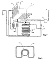
- FIG. 8 A preferred construction of this heat exchanger is in Fig. 8 shown.
- the evaporator 10 b is arranged in a longitudinal recess of the drain pipe 17.
- the drain pipe is designed as a plastic blower and presses elastically against the evaporator 10b.
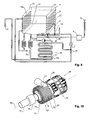
- a circulation pump 25 is shown, with which the process water from the sump 2 is conveyed below the tub 1 via a pumped circulation system 26 in the spray arms of the dishwasher.
- the first condenser 8 is arranged on the circulating pump 25. However, it is also conceivable for at least a partial arrangement at the sump 2 and / or a pumped circulation system 26. It in turn serves to supply heat to the process water during the cleaning phase. During this phase, the process water is pumped through the sump 2, the pump 25 and the pumped circulation system 26, so that they can be specifically heated there.
- a second capacitor 8 ' is provided be. This is in the dry phase together with the first evaporator 10a in operation to extract water from the process air in the manner described above.
- the second condenser 8 ' is arranged on a second side wall 15', which is opposite the first side wall 15 with the first evaporator 10a, so that good convection can be produced.
- the arrangement of the second capacitor 8 'on a side wall also has the advantage that the second condenser does not heat the water which drains through the bottom 12 in the dry phase, but selectively delivers its heat to the process air.
- the first condenser 8 and the second evaporator 10b are arranged in series with the expansion valve 9b interposed therebetween, so that the cooling medium can be passed through the first condenser 8 and the second evaporator 10b during the purge phase so as to extract heat from the drain area 16in to promote the process water.
- a switch 14' may be arranged to selectively supply the pumped medium to the first and the second capacitor 8 and 8 '.
- the first capacitor 8 in the embodiment after Fig. 9 preferably arranged on the circulation pump 25.
- a possible embodiment of the pump 25 with the first capacitor 8 is in Fig. 10 shown.
- the construction of the pump corresponds approximately to that according to DE 20 2007 017 077 U1 ,
- the pump has a housing 28 in which a pumping chamber 27 is arranged.
- a pumping chamber 27 In the pumping chamber 27 is an impeller (not visible in the figures), which is rotated by a motor 29 about a rotation axis 30.
- the construction of the pump for example Fig. 2 from DE 20 2007 017 077 U1 directed.
- the pumping chamber 27 has a cylindrical, to the axis of rotation 30 concentrically arranged wall 31.
- the majority of the pipeline of the first capacitor 8 meanders on the wall 31.
- the pipeline has a plurality of straight sections 32 parallel to the axis of rotation 30, which are connected via U-shaped bent portions 33 with each other.
- Fig. 10 extends the pipe of the condenser 8 into the axial, perpendicular to the axis of rotation 30 end wall 35 of the pumping chamber 27, whereby the heat exchange can be improved.
- the pipeline of the capacitor is arranged only on the cylindrical wall 31 of the pumping chamber 27.
- the pipeline of the condenser 8 can, as in Fig. 10 shown outside on the wall of the pumping chamber 27, or (as in below Fig. 11 shown) on the inside.
- FIG. 11 Another embodiment of the circulation pump 25 is in Fig. 11 which merely shows the cylindrical wall 31 of the pumping chamber 27.
- the pipeline of the capacitor 8 extends in a helix along the cylindrical wall 31.
- the helix is arranged coaxially to the axis of rotation 30.
- FIGS. 12 and 13 show a third embodiment of the circulation pump 25.
- the chamber 40 extends cylindrically around the pumping chamber 27.
- the wall of the housing 28 of the pumping chamber is double-walled.
- the medium is introduced via a first connecting piece 41 into the chamber 40 and discharged via a second connecting piece 42 again.
- a resistive heater may be provided, ie a heater which generates heat by passing an electrical current through a resistor.
- a heater allows, for example, to heat the water faster if necessary or to higher temperatures than would be possible with the condenser 8 alone.
- this heater is shown by reference numeral 36 and cuffed around an intake pipe 37, through which the water is sucked into the circulation pump 25.
Landscapes
- Engineering & Computer Science (AREA)
- Physics & Mathematics (AREA)
- Thermal Sciences (AREA)
- Mechanical Engineering (AREA)
- General Engineering & Computer Science (AREA)
- Water Supply & Treatment (AREA)
- Washing And Drying Of Tableware (AREA)
- Drying Of Solid Materials (AREA)
Priority Applications (3)
| Application Number | Priority Date | Filing Date | Title |
|---|---|---|---|
| SI200931706T SI2215954T1 (sl) | 2009-02-09 | 2009-04-17 | Pomivalni stroj s toplotno črpalko |
| PL09005447T PL2215954T3 (pl) | 2009-02-09 | 2009-04-17 | Zmywarka do naczyń z pompą ciepła |
| EP09005447.9A EP2215954B1 (fr) | 2009-02-09 | 2009-04-17 | Lave-vaisselle doté d'une pompe à chaleur |
Applications Claiming Priority (2)
| Application Number | Priority Date | Filing Date | Title |
|---|---|---|---|
| EP09001756A EP2064982B1 (fr) | 2009-02-09 | 2009-02-09 | Lave-vaisselle doté d'une pompe à chaleur |
| EP09005447.9A EP2215954B1 (fr) | 2009-02-09 | 2009-04-17 | Lave-vaisselle doté d'une pompe à chaleur |
Publications (2)
| Publication Number | Publication Date |
|---|---|
| EP2215954A1 true EP2215954A1 (fr) | 2010-08-11 |
| EP2215954B1 EP2215954B1 (fr) | 2017-05-17 |
Family
ID=40514576
Family Applications (5)
| Application Number | Title | Priority Date | Filing Date |
|---|---|---|---|
| EP11010220.9A Active EP2446796B1 (fr) | 2009-02-09 | 2009-02-09 | Lave-vaisselle doté d'une pompe à chaleur |
| EP09001756A Active EP2064982B1 (fr) | 2009-02-09 | 2009-02-09 | Lave-vaisselle doté d'une pompe à chaleur |
| EP11010219.1A Active EP2446795B1 (fr) | 2009-02-09 | 2009-02-09 | Lave-vaisselle doté d'une pompe à chaleur |
| EP09005448.7A Active EP2215955B1 (fr) | 2009-02-09 | 2009-04-17 | Lave-vaisselle doté d'une pompe à chaleur |
| EP09005447.9A Active EP2215954B1 (fr) | 2009-02-09 | 2009-04-17 | Lave-vaisselle doté d'une pompe à chaleur |
Family Applications Before (4)
| Application Number | Title | Priority Date | Filing Date |
|---|---|---|---|
| EP11010220.9A Active EP2446796B1 (fr) | 2009-02-09 | 2009-02-09 | Lave-vaisselle doté d'une pompe à chaleur |
| EP09001756A Active EP2064982B1 (fr) | 2009-02-09 | 2009-02-09 | Lave-vaisselle doté d'une pompe à chaleur |
| EP11010219.1A Active EP2446795B1 (fr) | 2009-02-09 | 2009-02-09 | Lave-vaisselle doté d'une pompe à chaleur |
| EP09005448.7A Active EP2215955B1 (fr) | 2009-02-09 | 2009-04-17 | Lave-vaisselle doté d'une pompe à chaleur |
Country Status (4)
| Country | Link |
|---|---|
| EP (5) | EP2446796B1 (fr) |
| DK (5) | DK2064982T3 (fr) |
| PL (5) | PL2064982T3 (fr) |
| SI (3) | SI2064982T1 (fr) |
Cited By (5)
| Publication number | Priority date | Publication date | Assignee | Title |
|---|---|---|---|---|
| EP2449945A2 (fr) | 2012-01-30 | 2012-05-09 | V-Zug AG | Appareil ménager doté d'une pompe à chaleur sur le circuit d'eau de traitement |
| DE102013114273B4 (de) * | 2013-12-18 | 2019-11-14 | Miele & Cie. Kg | Geschirrspülmaschine |
| WO2020069800A1 (fr) * | 2018-10-02 | 2020-04-09 | Arcelik Anonim Sirketi | Lave-vaisselle à pompe à chaleur comprenant une conduite de dégivrage |
| EP3988884A1 (fr) * | 2020-10-20 | 2022-04-27 | Haier Deutschland GmbH | Lave-vaisselle |
| DE102013114269B4 (de) | 2013-12-18 | 2026-04-02 | Miele & Cie. Kg | Geschirrspülmaschine |
Families Citing this family (66)
| Publication number | Priority date | Publication date | Assignee | Title |
|---|---|---|---|---|
| DE102009045547A1 (de) * | 2009-10-09 | 2011-04-14 | BSH Bosch und Siemens Hausgeräte GmbH | Verfahren zur Rückgewinnung von Energie aus der Wärme von Abwasser eines wasserführenden Haushaltsgerätes |
| DK2206824T3 (da) * | 2010-02-16 | 2013-10-07 | V Zug Ag | Husholdningsindretning med kar, varmepumpe og tank |
| IT1398885B1 (it) * | 2010-03-02 | 2013-03-21 | Indesit Co Spa | Metodo e macchina per il trattamento di stoviglie |
| DE102011000042A1 (de) * | 2011-01-05 | 2012-07-05 | Miele & Cie. Kg | Verfahren zum Durchführen eines Spülprogramms |
| EP2443984B1 (fr) | 2012-01-27 | 2020-06-17 | V-Zug AG | Echangeur thermique coaxial pour un appareil ménager |
| SI2443983T1 (sl) | 2012-01-27 | 2020-10-30 | V-Zug Ag | Gospodinjska naprava s toplotno črpalko, razmeščeno spodaj |
| EP2662013A1 (fr) | 2012-05-07 | 2013-11-13 | ELECTROLUX PROFESSIONAL S.p.A. | Machine à laver avec dispositif de séchage de pompe à chaleur et procédé associé |
| DE102012207980A1 (de) * | 2012-05-14 | 2013-11-14 | BSH Bosch und Siemens Hausgeräte GmbH | Vorrichtung zum Zwischenspeichern von Betriebsflüssigkeit |
| DE102012109363A1 (de) * | 2012-10-02 | 2014-04-03 | Miele & Cie. Kg | Geschirrspülautomat, insbesondere Haushaltsgeschirrspülmaschine |
| WO2014177187A1 (fr) * | 2013-04-30 | 2014-11-06 | Electrolux Appliances Aktiebolag | Appareil de lavage de pompe à chaleur |
| KR102094340B1 (ko) | 2014-03-17 | 2020-03-30 | 삼성전자주식회사 | 건조장치를 구비하는 가전제품 |
| WO2015155643A1 (fr) * | 2014-04-07 | 2015-10-15 | Indesit Company S.P.A. | Machine à laver et à sécher |
| US20170325651A1 (en) * | 2014-12-03 | 2017-11-16 | Arcelik Anonim Sirketi | Heat pump dishwasher |
| DE102015222940B4 (de) * | 2015-11-20 | 2017-07-06 | BSH Hausgeräte GmbH | Geschirrspülmaschine mit einer Wärmepumpe |
| US10541070B2 (en) | 2016-04-25 | 2020-01-21 | Haier Us Appliance Solutions, Inc. | Method for forming a bed of stabilized magneto-caloric material |
| US10299655B2 (en) * | 2016-05-16 | 2019-05-28 | General Electric Company | Caloric heat pump dishwasher appliance |
| US10274231B2 (en) | 2016-07-19 | 2019-04-30 | Haier Us Appliance Solutions, Inc. | Caloric heat pump system |
| US10295227B2 (en) | 2016-07-19 | 2019-05-21 | Haier Us Appliance Solutions, Inc. | Caloric heat pump system |
| US10281177B2 (en) | 2016-07-19 | 2019-05-07 | Haier Us Appliance Solutions, Inc. | Caloric heat pump system |
| US10222101B2 (en) | 2016-07-19 | 2019-03-05 | Haier Us Appliance Solutions, Inc. | Linearly-actuated magnetocaloric heat pump |
| US10443585B2 (en) | 2016-08-26 | 2019-10-15 | Haier Us Appliance Solutions, Inc. | Pump for a heat pump system |
| US10288326B2 (en) | 2016-12-06 | 2019-05-14 | Haier Us Appliance Solutions, Inc. | Conduction heat pump |
| US10386096B2 (en) | 2016-12-06 | 2019-08-20 | Haier Us Appliance Solutions, Inc. | Magnet assembly for a magneto-caloric heat pump |
| ES2672337B1 (es) * | 2016-12-13 | 2019-03-21 | Bsh Electrodomesticos Espana Sa | Máquina lavavajillas doméstica con disposición de bomba de calor |
| ES2672334B1 (es) * | 2016-12-13 | 2019-03-21 | Bsh Electrodomesticos Espana Sa | Máquina lavavajillas doméstica con disposición de bomba de calor |
| US10527325B2 (en) | 2017-03-28 | 2020-01-07 | Haier Us Appliance Solutions, Inc. | Refrigerator appliance |
| US11009282B2 (en) | 2017-03-28 | 2021-05-18 | Haier Us Appliance Solutions, Inc. | Refrigerator appliance with a caloric heat pump |
| US10451320B2 (en) | 2017-05-25 | 2019-10-22 | Haier Us Appliance Solutions, Inc. | Refrigerator appliance with water condensing features |
| US10422555B2 (en) | 2017-07-19 | 2019-09-24 | Haier Us Appliance Solutions, Inc. | Refrigerator appliance with a caloric heat pump |
| US10451322B2 (en) | 2017-07-19 | 2019-10-22 | Haier Us Appliance Solutions, Inc. | Refrigerator appliance with a caloric heat pump |
| ES2704146A1 (es) | 2017-09-14 | 2019-03-14 | Bsh Electrodomesticos Espana Sa | Máquina lavavajillas con al menos una bomba de calor |
| US10520229B2 (en) | 2017-11-14 | 2019-12-31 | Haier Us Appliance Solutions, Inc. | Caloric heat pump for an appliance |
| US11022348B2 (en) | 2017-12-12 | 2021-06-01 | Haier Us Appliance Solutions, Inc. | Caloric heat pump for an appliance |
| TR201721405A2 (tr) * | 2017-12-25 | 2019-07-22 | Arcelik As | Yikama suyu isitma performansi i̇yi̇leşti̇ri̇len isi pompali bulaşik maki̇nasi |
| CN110251016B (zh) * | 2018-03-12 | 2025-02-18 | 青岛海尔洗碗机有限公司 | 一种热泵式洗碗机 |
| US10876770B2 (en) | 2018-04-18 | 2020-12-29 | Haier Us Appliance Solutions, Inc. | Method for operating an elasto-caloric heat pump with variable pre-strain |
| US10557649B2 (en) | 2018-04-18 | 2020-02-11 | Haier Us Appliance Solutions, Inc. | Variable temperature magneto-caloric thermal diode assembly |
| US10551095B2 (en) | 2018-04-18 | 2020-02-04 | Haier Us Appliance Solutions, Inc. | Magneto-caloric thermal diode assembly |
| US10648706B2 (en) | 2018-04-18 | 2020-05-12 | Haier Us Appliance Solutions, Inc. | Magneto-caloric thermal diode assembly with an axially pinned magneto-caloric cylinder |
| US10782051B2 (en) | 2018-04-18 | 2020-09-22 | Haier Us Appliance Solutions, Inc. | Magneto-caloric thermal diode assembly |
| US10648704B2 (en) | 2018-04-18 | 2020-05-12 | Haier Us Appliance Solutions, Inc. | Magneto-caloric thermal diode assembly |
| US10648705B2 (en) | 2018-04-18 | 2020-05-12 | Haier Us Appliance Solutions, Inc. | Magneto-caloric thermal diode assembly |
| US10641539B2 (en) | 2018-04-18 | 2020-05-05 | Haier Us Appliance Solutions, Inc. | Magneto-caloric thermal diode assembly |
| US11054176B2 (en) | 2018-05-10 | 2021-07-06 | Haier Us Appliance Solutions, Inc. | Magneto-caloric thermal diode assembly with a modular magnet system |
| US10989449B2 (en) | 2018-05-10 | 2021-04-27 | Haier Us Appliance Solutions, Inc. | Magneto-caloric thermal diode assembly with radial supports |
| US11015842B2 (en) | 2018-05-10 | 2021-05-25 | Haier Us Appliance Solutions, Inc. | Magneto-caloric thermal diode assembly with radial polarity alignment |
| PL3801179T3 (pl) | 2018-06-08 | 2022-08-22 | Arçelik Anonim Sirketi | Zmywarka do naczyń z pompą ciepła z podwyższoną wydajnością parownika |
| US11092364B2 (en) | 2018-07-17 | 2021-08-17 | Haier Us Appliance Solutions, Inc. | Magneto-caloric thermal diode assembly with a heat transfer fluid circuit |
| US10684044B2 (en) | 2018-07-17 | 2020-06-16 | Haier Us Appliance Solutions, Inc. | Magneto-caloric thermal diode assembly with a rotating heat exchanger |
| WO2020057829A1 (fr) * | 2018-09-18 | 2020-03-26 | Arcelik Anonim Sirketi | Lave-vaisselle comprenant une pompe à chaleur |
| EP3855997B1 (fr) | 2018-09-26 | 2024-02-07 | Arçelik Anonim Sirketi | Lave-vaisselle à pompe à chaleur avec consommation d'eau réduite |
| KR102588120B1 (ko) | 2018-11-27 | 2023-10-13 | 엘지전자 주식회사 | 식기세척기 |
| KR102603450B1 (ko) * | 2018-11-28 | 2023-11-20 | 엘지전자 주식회사 | 히트펌프를 구비한 식기세척기 |
| US11168926B2 (en) | 2019-01-08 | 2021-11-09 | Haier Us Appliance Solutions, Inc. | Leveraged mechano-caloric heat pump |
| US11193697B2 (en) | 2019-01-08 | 2021-12-07 | Haier Us Appliance Solutions, Inc. | Fan speed control method for caloric heat pump systems |
| US11274860B2 (en) | 2019-01-08 | 2022-03-15 | Haier Us Appliance Solutions, Inc. | Mechano-caloric stage with inner and outer sleeves |
| US11149994B2 (en) | 2019-01-08 | 2021-10-19 | Haier Us Appliance Solutions, Inc. | Uneven flow valve for a caloric regenerator |
| US11112146B2 (en) | 2019-02-12 | 2021-09-07 | Haier Us Appliance Solutions, Inc. | Heat pump and cascaded caloric regenerator assembly |
| US11015843B2 (en) | 2019-05-29 | 2021-05-25 | Haier Us Appliance Solutions, Inc. | Caloric heat pump hydraulic system |
| EP3747336B1 (fr) | 2019-06-03 | 2023-05-03 | BSH Hausgeräte GmbH | Lave-vaisselle comprenant au moins une pompe à chaleur |
| EP3747334B1 (fr) | 2019-06-03 | 2024-07-10 | BSH Hausgeräte GmbH | Lave-vaisselle électroménager pourvu d'au moins une pompe à chaleur |
| WO2023186277A1 (fr) * | 2022-03-30 | 2023-10-05 | Electrolux Appliances Aktiebolag | Machine de traitement du linge avec pompe à chaleur |
| KR20230174405A (ko) | 2022-06-21 | 2023-12-28 | 엘지전자 주식회사 | 열펌프장치를 포함하는 식기세척기 |
| KR20240001344A (ko) | 2022-06-24 | 2024-01-03 | 엘지전자 주식회사 | 열펌프장치를 포함하는 식기세척기 |
| DE102023100906A1 (de) * | 2023-01-16 | 2024-07-18 | Illinois Tool Works Inc. | Spülmaschine mit wärmerückgewinnungsvorrichtung |
| DE102024200556A1 (de) * | 2024-01-22 | 2025-07-24 | BSH Hausgeräte GmbH | Geschirrspülmaschine mit einer Wärmepumpe sowie zugehöriges Betriebsverfahren |
Citations (6)
| Publication number | Priority date | Publication date | Assignee | Title |
|---|---|---|---|---|
| DE2326246A1 (de) * | 1973-05-23 | 1974-12-12 | Tappan Co | Heizvorrichtung insbesondere fuer geschirrspuelapparate |
| DE3048268A1 (de) * | 1980-12-20 | 1982-07-29 | Stierlen-Maquet Ag, 7550 Rastatt | Waermerueckgewinnungseinrichtung fuer geschirrspuelmaschinen |
| JPH1080391A (ja) * | 1996-09-10 | 1998-03-31 | Hoshizaki Electric Co Ltd | 食器洗浄機の温水生成装置 |
| EP1864603A2 (fr) * | 2007-06-14 | 2007-12-12 | V-Zug AG | Lave-vaisselle avec récupération de chaleur |
| DE202007017077U1 (de) | 2007-12-07 | 2008-02-21 | V-Zug Ag | Haushaltgerät, insbesondere Geschirrspüler mit Umwälzpumpe und integrierter Heizung |
| EP1917899A1 (fr) * | 2006-10-30 | 2008-05-07 | Constructions Isothermiques Bontami - C.I.B. | Machine à laver la vaisselle et pompe à chaleur |
-
2009
- 2009-02-09 EP EP11010220.9A patent/EP2446796B1/fr active Active
- 2009-02-09 PL PL09001756T patent/PL2064982T3/pl unknown
- 2009-02-09 DK DK09001756.7T patent/DK2064982T3/da active
- 2009-02-09 PL PL11010220T patent/PL2446796T3/pl unknown
- 2009-02-09 PL PL11010219T patent/PL2446795T3/pl unknown
- 2009-02-09 DK DK11010220.9T patent/DK2446796T3/da active
- 2009-02-09 EP EP09001756A patent/EP2064982B1/fr active Active
- 2009-02-09 SI SI200930312T patent/SI2064982T1/sl unknown
- 2009-02-09 EP EP11010219.1A patent/EP2446795B1/fr active Active
- 2009-02-09 DK DK11010219.1T patent/DK2446795T3/da active
- 2009-04-17 DK DK09005447.9T patent/DK2215954T3/en active
- 2009-04-17 DK DK09005448.7T patent/DK2215955T3/en active
- 2009-04-17 SI SI200931706T patent/SI2215954T1/sl unknown
- 2009-04-17 PL PL09005448T patent/PL2215955T3/pl unknown
- 2009-04-17 EP EP09005448.7A patent/EP2215955B1/fr active Active
- 2009-04-17 EP EP09005447.9A patent/EP2215954B1/fr active Active
- 2009-04-17 PL PL09005447T patent/PL2215954T3/pl unknown
- 2009-04-17 SI SI200931739T patent/SI2215955T1/sl unknown
Patent Citations (6)
| Publication number | Priority date | Publication date | Assignee | Title |
|---|---|---|---|---|
| DE2326246A1 (de) * | 1973-05-23 | 1974-12-12 | Tappan Co | Heizvorrichtung insbesondere fuer geschirrspuelapparate |
| DE3048268A1 (de) * | 1980-12-20 | 1982-07-29 | Stierlen-Maquet Ag, 7550 Rastatt | Waermerueckgewinnungseinrichtung fuer geschirrspuelmaschinen |
| JPH1080391A (ja) * | 1996-09-10 | 1998-03-31 | Hoshizaki Electric Co Ltd | 食器洗浄機の温水生成装置 |
| EP1917899A1 (fr) * | 2006-10-30 | 2008-05-07 | Constructions Isothermiques Bontami - C.I.B. | Machine à laver la vaisselle et pompe à chaleur |
| EP1864603A2 (fr) * | 2007-06-14 | 2007-12-12 | V-Zug AG | Lave-vaisselle avec récupération de chaleur |
| DE202007017077U1 (de) | 2007-12-07 | 2008-02-21 | V-Zug Ag | Haushaltgerät, insbesondere Geschirrspüler mit Umwälzpumpe und integrierter Heizung |
Cited By (8)
| Publication number | Priority date | Publication date | Assignee | Title |
|---|---|---|---|---|
| EP2449945A2 (fr) | 2012-01-30 | 2012-05-09 | V-Zug AG | Appareil ménager doté d'une pompe à chaleur sur le circuit d'eau de traitement |
| EP2449945A3 (fr) * | 2012-01-30 | 2012-08-29 | V-Zug AG | Appareil ménager doté d'une pompe à chaleur sur le circuit d'eau de traitement |
| DE102013114273B4 (de) * | 2013-12-18 | 2019-11-14 | Miele & Cie. Kg | Geschirrspülmaschine |
| DE102013114269B4 (de) | 2013-12-18 | 2026-04-02 | Miele & Cie. Kg | Geschirrspülmaschine |
| WO2020069800A1 (fr) * | 2018-10-02 | 2020-04-09 | Arcelik Anonim Sirketi | Lave-vaisselle à pompe à chaleur comprenant une conduite de dégivrage |
| EP3988884A1 (fr) * | 2020-10-20 | 2022-04-27 | Haier Deutschland GmbH | Lave-vaisselle |
| WO2022084279A1 (fr) * | 2020-10-20 | 2022-04-28 | Haier Deutschland GmbH | Lave-vaisselle |
| CN116490741A (zh) * | 2020-10-20 | 2023-07-25 | 海尔德国股份有限公司 | 洗碗机 |
Also Published As
| Publication number | Publication date |
|---|---|
| PL2064982T3 (pl) | 2012-11-30 |
| PL2446795T3 (pl) | 2014-06-30 |
| DK2215954T3 (en) | 2017-07-17 |
| EP2446795A2 (fr) | 2012-05-02 |
| EP2064982A1 (fr) | 2009-06-03 |
| DK2446796T3 (da) | 2014-01-20 |
| DK2446795T3 (da) | 2014-01-27 |
| EP2215955B1 (fr) | 2017-07-26 |
| EP2446795A3 (fr) | 2012-07-25 |
| PL2446796T3 (pl) | 2014-05-30 |
| EP2064982B1 (fr) | 2012-06-27 |
| EP2446796B1 (fr) | 2013-12-11 |
| SI2215955T1 (sl) | 2017-11-30 |
| DK2215955T3 (en) | 2017-10-16 |
| EP2215954B1 (fr) | 2017-05-17 |
| PL2215955T3 (pl) | 2018-02-28 |
| DK2064982T3 (da) | 2012-07-23 |
| EP2446796A3 (fr) | 2012-07-25 |
| SI2215954T1 (sl) | 2017-08-31 |
| EP2446795B1 (fr) | 2014-01-08 |
| EP2215955A1 (fr) | 2010-08-11 |
| EP2446796A2 (fr) | 2012-05-02 |
| PL2215954T3 (pl) | 2017-10-31 |
| SI2064982T1 (sl) | 2012-09-28 |
Similar Documents
| Publication | Publication Date | Title |
|---|---|---|
| EP2215954B1 (fr) | Lave-vaisselle doté d'une pompe à chaleur | |
| EP2322072B1 (fr) | Lave-vaisselle doté d'un accumulateur thermique latent | |
| EP2057928B1 (fr) | Installation de nettoyage dotée d'un accumulateur thermique latent | |
| EP1791459B1 (fr) | Procédé de séchage pour un appareil électroménager et appareil électroménager | |
| EP1651090B1 (fr) | Lave-vaisselle | |
| EP2605691B1 (fr) | Procédé et dispositif pour sécher de l'air humide | |
| EP2682039B1 (fr) | Lave-vaisselle doté d'une pompe à chaleur | |
| EP2206824A2 (fr) | Appareil ménager doté d'une cuve, d'une pompe à chaleur et d'un réservoir | |
| CH699692B1 (de) | Geschirrspüler mit mehreren Wassertanks. | |
| EP1651091B1 (fr) | Machine a laver la vaisselle a tube de chauffage | |
| WO2007074024A1 (fr) | Lave-vaisselle | |
| WO2017195057A1 (fr) | Lave-vaisselle et procédé pour nettoyer et sécher de la vaisselle | |
| DE102019131954A1 (de) | Geschirrspülmaschine mit Wärmepumpe | |
| WO2006063895A1 (fr) | Lave-vaisselle domestique et son procede de fonctionnement | |
| DE102015109509B3 (de) | Geschirrspülmaschine, insbesondere Haushaltsgeschirrspülmaschine | |
| EP2286708A2 (fr) | Lave-vaisselle doté d'un support de sorption et de circuits de condensation et de séchage au moins partiellement divisés | |
| WO2019020353A1 (fr) | Pompe à chaleur : évacuation de la chaleur du condenseur via un circuit supplémentaire | |
| EP2682040B1 (fr) | Procédé de fonctionnement d'un lave-vaisselle | |
| EP3034670A1 (fr) | Dispositif et procede de chauffage d'un fluide de traitement pour un appareil de traitement de linge et appareil de traitement de linge | |
| DE102019218097A1 (de) | Energierückgewinnungstauscher | |
| WO2019049007A2 (fr) | Moyen pour empêcher l'encrassement d'un condenseur à plaques d'un lave-vaisselle ménager | |
| DE102016107872A1 (de) | Transportspülmaschine sowie Verfahren zum Betreiben einer Transportspülmaschine | |
| DE102024200556A1 (de) | Geschirrspülmaschine mit einer Wärmepumpe sowie zugehöriges Betriebsverfahren | |
| EP1651092A1 (fr) | Procede pour faire fonctionner un appareil avec au moins une etape de sous-programme "sechage" | |
| WO2025157479A1 (fr) | Lave-vaisselle avec pompe à chaleur |
Legal Events
| Date | Code | Title | Description |
|---|---|---|---|
| PUAI | Public reference made under article 153(3) epc to a published international application that has entered the european phase |
Free format text: ORIGINAL CODE: 0009012 |
|
| AK | Designated contracting states |
Kind code of ref document: A1 Designated state(s): AT BE BG CH CY CZ DE DK EE ES FI FR GB GR HR HU IE IS IT LI LT LU LV MC MK MT NL NO PL PT RO SE SI SK TR |
|
| AX | Request for extension of the european patent |
Extension state: AL BA RS |
|
| 17P | Request for examination filed |
Effective date: 20110128 |
|
| GRAP | Despatch of communication of intention to grant a patent |
Free format text: ORIGINAL CODE: EPIDOSNIGR1 |
|
| INTG | Intention to grant announced |
Effective date: 20170109 |
|
| GRAS | Grant fee paid |
Free format text: ORIGINAL CODE: EPIDOSNIGR3 |
|
| GRAA | (expected) grant |
Free format text: ORIGINAL CODE: 0009210 |
|
| AK | Designated contracting states |
Kind code of ref document: B1 Designated state(s): AT BE BG CH CY CZ DE DK EE ES FI FR GB GR HR HU IE IS IT LI LT LU LV MC MK MT NL NO PL PT RO SE SI SK TR |
|
| REG | Reference to a national code |
Ref country code: GB Ref legal event code: FG4D Free format text: NOT ENGLISH |
|
| REG | Reference to a national code |
Ref country code: CH Ref legal event code: EP |
|
| REG | Reference to a national code |
Ref country code: IE Ref legal event code: FG4D Free format text: LANGUAGE OF EP DOCUMENT: GERMAN |
|
| REG | Reference to a national code |
Ref country code: AT Ref legal event code: REF Ref document number: 893681 Country of ref document: AT Kind code of ref document: T Effective date: 20170615 |
|
| REG | Reference to a national code |
Ref country code: DE Ref legal event code: R096 Ref document number: 502009013969 Country of ref document: DE |
|
| REG | Reference to a national code |
Ref country code: DK Ref legal event code: T3 Effective date: 20170707 |
|
| REG | Reference to a national code |
Ref country code: SE Ref legal event code: TRGR |
|
| REG | Reference to a national code |
Ref country code: NL Ref legal event code: MP Effective date: 20170517 |
|
| REG | Reference to a national code |
Ref country code: LT Ref legal event code: MG4D |
|
| PG25 | Lapsed in a contracting state [announced via postgrant information from national office to epo] |
Ref country code: HR Free format text: LAPSE BECAUSE OF FAILURE TO SUBMIT A TRANSLATION OF THE DESCRIPTION OR TO PAY THE FEE WITHIN THE PRESCRIBED TIME-LIMIT Effective date: 20170517 Ref country code: FI Free format text: LAPSE BECAUSE OF FAILURE TO SUBMIT A TRANSLATION OF THE DESCRIPTION OR TO PAY THE FEE WITHIN THE PRESCRIBED TIME-LIMIT Effective date: 20170517 Ref country code: ES Free format text: LAPSE BECAUSE OF FAILURE TO SUBMIT A TRANSLATION OF THE DESCRIPTION OR TO PAY THE FEE WITHIN THE PRESCRIBED TIME-LIMIT Effective date: 20170517 Ref country code: NO Free format text: LAPSE BECAUSE OF FAILURE TO SUBMIT A TRANSLATION OF THE DESCRIPTION OR TO PAY THE FEE WITHIN THE PRESCRIBED TIME-LIMIT Effective date: 20170817 Ref country code: LT Free format text: LAPSE BECAUSE OF FAILURE TO SUBMIT A TRANSLATION OF THE DESCRIPTION OR TO PAY THE FEE WITHIN THE PRESCRIBED TIME-LIMIT Effective date: 20170517 Ref country code: GR Free format text: LAPSE BECAUSE OF FAILURE TO SUBMIT A TRANSLATION OF THE DESCRIPTION OR TO PAY THE FEE WITHIN THE PRESCRIBED TIME-LIMIT Effective date: 20170818 |
|
| PG25 | Lapsed in a contracting state [announced via postgrant information from national office to epo] |
Ref country code: BG Free format text: LAPSE BECAUSE OF FAILURE TO SUBMIT A TRANSLATION OF THE DESCRIPTION OR TO PAY THE FEE WITHIN THE PRESCRIBED TIME-LIMIT Effective date: 20170817 Ref country code: IS Free format text: LAPSE BECAUSE OF FAILURE TO SUBMIT A TRANSLATION OF THE DESCRIPTION OR TO PAY THE FEE WITHIN THE PRESCRIBED TIME-LIMIT Effective date: 20170917 Ref country code: NL Free format text: LAPSE BECAUSE OF FAILURE TO SUBMIT A TRANSLATION OF THE DESCRIPTION OR TO PAY THE FEE WITHIN THE PRESCRIBED TIME-LIMIT Effective date: 20170517 Ref country code: LV Free format text: LAPSE BECAUSE OF FAILURE TO SUBMIT A TRANSLATION OF THE DESCRIPTION OR TO PAY THE FEE WITHIN THE PRESCRIBED TIME-LIMIT Effective date: 20170517 |
|
| PG25 | Lapsed in a contracting state [announced via postgrant information from national office to epo] |
Ref country code: EE Free format text: LAPSE BECAUSE OF FAILURE TO SUBMIT A TRANSLATION OF THE DESCRIPTION OR TO PAY THE FEE WITHIN THE PRESCRIBED TIME-LIMIT Effective date: 20170517 Ref country code: CZ Free format text: LAPSE BECAUSE OF FAILURE TO SUBMIT A TRANSLATION OF THE DESCRIPTION OR TO PAY THE FEE WITHIN THE PRESCRIBED TIME-LIMIT Effective date: 20170517 Ref country code: RO Free format text: LAPSE BECAUSE OF FAILURE TO SUBMIT A TRANSLATION OF THE DESCRIPTION OR TO PAY THE FEE WITHIN THE PRESCRIBED TIME-LIMIT Effective date: 20170517 Ref country code: SK Free format text: LAPSE BECAUSE OF FAILURE TO SUBMIT A TRANSLATION OF THE DESCRIPTION OR TO PAY THE FEE WITHIN THE PRESCRIBED TIME-LIMIT Effective date: 20170517 |
|
| REG | Reference to a national code |
Ref country code: DE Ref legal event code: R097 Ref document number: 502009013969 Country of ref document: DE |
|
| PG25 | Lapsed in a contracting state [announced via postgrant information from national office to epo] |
Ref country code: IT Free format text: LAPSE BECAUSE OF FAILURE TO SUBMIT A TRANSLATION OF THE DESCRIPTION OR TO PAY THE FEE WITHIN THE PRESCRIBED TIME-LIMIT Effective date: 20170517 |
|
| PLBE | No opposition filed within time limit |
Free format text: ORIGINAL CODE: 0009261 |
|
| STAA | Information on the status of an ep patent application or granted ep patent |
Free format text: STATUS: NO OPPOSITION FILED WITHIN TIME LIMIT |
|
| REG | Reference to a national code |
Ref country code: FR Ref legal event code: PLFP Year of fee payment: 10 |
|
| 26N | No opposition filed |
Effective date: 20180220 |
|
| PGFP | Annual fee paid to national office [announced via postgrant information from national office to epo] |
Ref country code: PL Payment date: 20180322 Year of fee payment: 10 |
|
| PGFP | Annual fee paid to national office [announced via postgrant information from national office to epo] |
Ref country code: DK Payment date: 20180418 Year of fee payment: 10 |
|
| PGFP | Annual fee paid to national office [announced via postgrant information from national office to epo] |
Ref country code: FR Payment date: 20180420 Year of fee payment: 10 Ref country code: SI Payment date: 20180403 Year of fee payment: 10 |
|
| REG | Reference to a national code |
Ref country code: SI Ref legal event code: SP73 Owner name: V-ZUG AG; CH Effective date: 20180629 |
|
| PG25 | Lapsed in a contracting state [announced via postgrant information from national office to epo] |
Ref country code: MT Free format text: LAPSE BECAUSE OF FAILURE TO SUBMIT A TRANSLATION OF THE DESCRIPTION OR TO PAY THE FEE WITHIN THE PRESCRIBED TIME-LIMIT Effective date: 20170517 |
|
| PGFP | Annual fee paid to national office [announced via postgrant information from national office to epo] |
Ref country code: SE Payment date: 20180418 Year of fee payment: 10 |
|
| PGFP | Annual fee paid to national office [announced via postgrant information from national office to epo] |
Ref country code: GB Payment date: 20180418 Year of fee payment: 10 |
|
| PG25 | Lapsed in a contracting state [announced via postgrant information from national office to epo] |
Ref country code: MC Free format text: LAPSE BECAUSE OF FAILURE TO SUBMIT A TRANSLATION OF THE DESCRIPTION OR TO PAY THE FEE WITHIN THE PRESCRIBED TIME-LIMIT Effective date: 20170517 |
|
| REG | Reference to a national code |
Ref country code: BE Ref legal event code: MM Effective date: 20180430 |
|
| REG | Reference to a national code |
Ref country code: IE Ref legal event code: MM4A |
|
| PG25 | Lapsed in a contracting state [announced via postgrant information from national office to epo] |
Ref country code: LU Free format text: LAPSE BECAUSE OF NON-PAYMENT OF DUE FEES Effective date: 20180417 |
|
| PG25 | Lapsed in a contracting state [announced via postgrant information from national office to epo] |
Ref country code: BE Free format text: LAPSE BECAUSE OF NON-PAYMENT OF DUE FEES Effective date: 20180430 |
|
| PG25 | Lapsed in a contracting state [announced via postgrant information from national office to epo] |
Ref country code: IE Free format text: LAPSE BECAUSE OF NON-PAYMENT OF DUE FEES Effective date: 20180417 |
|
| REG | Reference to a national code |
Ref country code: AT Ref legal event code: MM01 Ref document number: 893681 Country of ref document: AT Kind code of ref document: T Effective date: 20180417 |
|
| PG25 | Lapsed in a contracting state [announced via postgrant information from national office to epo] |
Ref country code: AT Free format text: LAPSE BECAUSE OF NON-PAYMENT OF DUE FEES Effective date: 20180417 |
|
| REG | Reference to a national code |
Ref country code: DK Ref legal event code: EBP Effective date: 20190430 |
|
| REG | Reference to a national code |
Ref country code: SE Ref legal event code: EUG |
|
| GBPC | Gb: european patent ceased through non-payment of renewal fee |
Effective date: 20190417 |
|
| PG25 | Lapsed in a contracting state [announced via postgrant information from national office to epo] |
Ref country code: SE Free format text: LAPSE BECAUSE OF NON-PAYMENT OF DUE FEES Effective date: 20190418 Ref country code: GB Free format text: LAPSE BECAUSE OF NON-PAYMENT OF DUE FEES Effective date: 20190417 |
|
| PG25 | Lapsed in a contracting state [announced via postgrant information from national office to epo] |
Ref country code: SI Free format text: LAPSE BECAUSE OF NON-PAYMENT OF DUE FEES Effective date: 20190418 Ref country code: FR Free format text: LAPSE BECAUSE OF NON-PAYMENT OF DUE FEES Effective date: 20190430 |
|
| PG25 | Lapsed in a contracting state [announced via postgrant information from national office to epo] |
Ref country code: TR Free format text: LAPSE BECAUSE OF FAILURE TO SUBMIT A TRANSLATION OF THE DESCRIPTION OR TO PAY THE FEE WITHIN THE PRESCRIBED TIME-LIMIT Effective date: 20170517 |
|
| PG25 | Lapsed in a contracting state [announced via postgrant information from national office to epo] |
Ref country code: DK Free format text: LAPSE BECAUSE OF NON-PAYMENT OF DUE FEES Effective date: 20190430 |
|
| PG25 | Lapsed in a contracting state [announced via postgrant information from national office to epo] |
Ref country code: PT Free format text: LAPSE BECAUSE OF FAILURE TO SUBMIT A TRANSLATION OF THE DESCRIPTION OR TO PAY THE FEE WITHIN THE PRESCRIBED TIME-LIMIT Effective date: 20170517 Ref country code: HU Free format text: LAPSE BECAUSE OF FAILURE TO SUBMIT A TRANSLATION OF THE DESCRIPTION OR TO PAY THE FEE WITHIN THE PRESCRIBED TIME-LIMIT; INVALID AB INITIO Effective date: 20090417 |
|
| PG25 | Lapsed in a contracting state [announced via postgrant information from national office to epo] |
Ref country code: CY Free format text: LAPSE BECAUSE OF FAILURE TO SUBMIT A TRANSLATION OF THE DESCRIPTION OR TO PAY THE FEE WITHIN THE PRESCRIBED TIME-LIMIT Effective date: 20170517 Ref country code: MK Free format text: LAPSE BECAUSE OF NON-PAYMENT OF DUE FEES Effective date: 20170517 |
|
| PG25 | Lapsed in a contracting state [announced via postgrant information from national office to epo] |
Ref country code: PL Free format text: LAPSE BECAUSE OF NON-PAYMENT OF DUE FEES Effective date: 20190417 |
|
| P01 | Opt-out of the competence of the unified patent court (upc) registered |
Effective date: 20230502 |
|
| PGFP | Annual fee paid to national office [announced via postgrant information from national office to epo] |
Ref country code: DE Payment date: 20250422 Year of fee payment: 17 |
|
| PGFP | Annual fee paid to national office [announced via postgrant information from national office to epo] |
Ref country code: CH Payment date: 20250501 Year of fee payment: 17 |