EP2216464A2 - Plateforme modulable - Google Patents
Plateforme modulable Download PDFInfo
- Publication number
- EP2216464A2 EP2216464A2 EP20100305121 EP10305121A EP2216464A2 EP 2216464 A2 EP2216464 A2 EP 2216464A2 EP 20100305121 EP20100305121 EP 20100305121 EP 10305121 A EP10305121 A EP 10305121A EP 2216464 A2 EP2216464 A2 EP 2216464A2
- Authority
- EP
- European Patent Office
- Prior art keywords
- central portion
- floor
- axis
- module
- modules
- Prior art date
- Legal status (The legal status is an assumption and is not a legal conclusion. Google has not performed a legal analysis and makes no representation as to the accuracy of the status listed.)
- Granted
Links
Images




Classifications
-
- E—FIXED CONSTRUCTIONS
- E04—BUILDING
- E04G—SCAFFOLDING; FORMS; SHUTTERING; BUILDING IMPLEMENTS OR AIDS, OR THEIR USE; HANDLING BUILDING MATERIALS ON THE SITE; REPAIRING, BREAKING-UP OR OTHER WORK ON EXISTING BUILDINGS
- E04G7/00—Connections between parts of the scaffold
- E04G7/02—Connections between parts of the scaffold with separate coupling elements
- E04G7/28—Clips or connections for securing boards
-
- E—FIXED CONSTRUCTIONS
- E04—BUILDING
- E04G—SCAFFOLDING; FORMS; SHUTTERING; BUILDING IMPLEMENTS OR AIDS, OR THEIR USE; HANDLING BUILDING MATERIALS ON THE SITE; REPAIRING, BREAKING-UP OR OTHER WORK ON EXISTING BUILDINGS
- E04G1/00—Scaffolds primarily resting on the ground
- E04G1/34—Scaffold constructions able to be folded in prismatic or flat parts or able to be turned down
-
- E—FIXED CONSTRUCTIONS
- E04—BUILDING
- E04G—SCAFFOLDING; FORMS; SHUTTERING; BUILDING IMPLEMENTS OR AIDS, OR THEIR USE; HANDLING BUILDING MATERIALS ON THE SITE; REPAIRING, BREAKING-UP OR OTHER WORK ON EXISTING BUILDINGS
- E04G5/00—Component parts or accessories for scaffolds
- E04G5/14—Railings
-
- E—FIXED CONSTRUCTIONS
- E04—BUILDING
- E04G—SCAFFOLDING; FORMS; SHUTTERING; BUILDING IMPLEMENTS OR AIDS, OR THEIR USE; HANDLING BUILDING MATERIALS ON THE SITE; REPAIRING, BREAKING-UP OR OTHER WORK ON EXISTING BUILDINGS
- E04G5/00—Component parts or accessories for scaffolds
- E04G5/14—Railings
- E04G5/141—Railings with an access door or the like therefor
-
- E—FIXED CONSTRUCTIONS
- E04—BUILDING
- E04G—SCAFFOLDING; FORMS; SHUTTERING; BUILDING IMPLEMENTS OR AIDS, OR THEIR USE; HANDLING BUILDING MATERIALS ON THE SITE; REPAIRING, BREAKING-UP OR OTHER WORK ON EXISTING BUILDINGS
- E04G1/00—Scaffolds primarily resting on the ground
- E04G1/24—Scaffolds primarily resting on the ground comprising essentially special base constructions; comprising essentially special ground-engaging parts, e.g. inclined struts, wheels
- E04G2001/242—Scaffolds movable on wheels or tracks
Definitions
- the present invention relates to a modular platform.
- a plasterer uses scaffolding comprising a floor supported by uprights and equipped with railings or guardrails.
- the floor has fixed dimensions which are not generally adapted to the work site.
- users have to move their scaffolds regularly.
- they have several scaffolds attached to each other.
- the document AU503902 describes modules each having a floor with at each end of the tips with orifices. These holes make it possible to receive a hook shaped 5 to connect two modules to form a platform. These hooks in 5 have a round section.
- the endpieces comprise notches in a semicircle for accommodating the central portion of the hooks.
- the present invention lives to overcome the disadvantages of the prior art, by providing a safe modular platform, convenient to use and easily movable.
- the subject of the invention is a modular platform comprising at least two modules each comprising a floor with longitudinal edges and transverse edges and two supports and two connecting hooks providing the connection between two adjacent modules, a hook of link having a shape of 5 and comprising a central portion, at a first end of said central portion an axis substantially parallel to the central portion facing a second end of said central portion engageable with an orifice provided at the level of the upper surface of the floor of a module, and secondly, at the second end of said central portion an axis substantially parallel to the central portion facing the first end of said central portion capable of cooperating with a hollow tube integral with the floor of a module whose section is adapted to that of the axis, characterized in that the central part of each connecting hook is flat and extended at a first end by a first wing bent at 90 ° in a first direction and at a second end by a second wing bent at 90 ° in a second direction opposite to the first direction .
- a module 10 of a first type comprising a floor 12 and two supports 14.
- the floor 12 has a rectangular shape. As an indication, the floor has a length of the order of 2 m and a width of about 0.8 m.
- longitudinal direction means the direction corresponding to the length of the floor while the transverse direction corresponds to the width.
- the floor 12 is made from a sheet whose edges are bent at 90 ° so as to form longitudinal edges 16 and transverse edges 18.
- the floor and the transverse and longitudinal edges form a cavity in which can be arranged the supports 14 folded, as will be explained later.
- the module 10 has a parallelepipedal shape so that the modules can be easily stacked on each other.
- each support 14 comprises two uprights 20 connected by two crosspieces 22, each of said uprights 20 having a first pivoting end relative to a plate 24 secured to the floor according to a pivot axis 25 oriented in the transverse direction.
- each upright is adjustable in length.
- each upright comprises two tubes which slide in one another, the first being pivotable relative to the plate, the second sliding in the first and comprising at its outgoing end a yoke 26 supporting a wheel 28.
- the wheel 28 is steerable and can rotate about an axis parallel to the direction of the amount as materialized by the double arrow 30.
- the first tube comprises a single through hole oriented in the transverse direction, the second tube comprising a succession of holes adapted to cooperate with that of the first tube.
- a pin adapted to be housed in the hole of the first tube and one of the holes of the second tube makes it possible to prevent the second tube from sliding in the first tube and thus to adjust the length of the upright.
- the tubes have square sections.
- a plate 24 comprises a hollow tube 32 with a square section, oriented perpendicularly to the floor 12, and two wings 34 on either side of said hollow tube 32 to ensure its connection with a longitudinal edge 16 to close to a transverse edge 18.
- the connection between the plate 24 and the longitudinal edge 16 is provided by any appropriate means, for example by riveting (four rivets according to the illustrated example).
- a cutout 36 is made at the floor 12 so as to make the hollow tube 32 of the plate accessible from the top of the floor as shown in FIG. figure 3 .
- a rod or a tube providing the rotational axis function.
- each module 10 of the first type comprises two supports, each pivoting about a transverse axis of rotation disposed near a transverse edge.
- Each support can occupy two states, a first deployed state, as shown to the left of the figure 1 , in which the support is disposed at 90 ° to the floor, and a second folded state, as shown to the right of the figure 1 in which the support is arranged parallel to the floor.
- Each support 14 has a leg 38 to keep it in the deployed state.
- a leg 38 comprises a first sleeve 40 which can pivot on a crosspiece 22 of the corresponding support, in particular the crosspiece farthest from the axis of pivoting of the support, a rod 42 extending in the longitudinal direction and a first end of which is connected to the first sleeve 40, a second sleeve 44 into which the rod 42 can slide, a third sleeve 46 secured to the second sleeve 44 adapted to pivot on an axis 48 extending in the transverse direction and whose ends are integral with the longitudinal edges of the floor.
- a pin is provided to limit the sliding movement of the rod 42 in the second sleeve 44 and thus maintain the support in the deployed state.
- the same axis 48 is used for the two jamb / support assemblies of the same module 10.
- module 50 of a second type Unlike a module 10 of the first type, it does not include support or jamb. It comprises only a floor 12 and plates 24 each with a hollow tube 32 accessible from the top of the floor through a cutout 36.
- the modules 50 of the second type have dimensions similar to the modules 10 of the first type.
- one or more modules 10 of the first type can be used next to one another.
- modules 10 of the first type are connected by means of a module 50 of the second type.
- the platform includes connecting hooks 52 illustrated on the Figures 5, 6 , 11A and 11B .
- a connecting hook 52 comprises a plate-shaped 5 with a flat central portion 54 extended at a first end by a first flange 56 bent at 90 ° in a first direction and at a second end by a second flange 58 bent at 90 ° in a second direction opposite to the first direction.
- the hook 52 comprises firstly at the first flange 56 an axis 60 substantially parallel to the central portion 54 facing the second end of said central portion 54 engageable with an orifice 62 provided at the level of the upper surface of the floor of a module 10 of the first type, preferably equidistance of the edges, and secondly, at the second flange 58 a tube 64 substantially parallel to the central portion 54 facing the first end of said central portion 54 engageable with a hollow tube 66 whose section is adapted to that of the tube 64 so that the latter slides in said hollow tube 66 virtually free play.
- the tube 64 has a square section.
- the tube 64 and the axis 60 are arranged in a plane perpendicular to the plane of the central portion 54.
- the hollow tube 66 is disposed equidistant from the longitudinal edge and the transverse edge and secured to a plate 24.
- the distance between the tube 64 and the central portion 54 noted E on the figure 5 is substantially equal to the distance separating the outer face of the longitudinal song or the transverse edge and the inner face of the hollow tube 66.
- the distance between the axis 60 and the central portion 54, noted E1 on the figure 5 is substantially equal to the distance separating the axis of the orifice 62 from the longitudinal edge and the transverse edge.
- the length of the central portion 54 substantially corresponds to the height of a song.
- a hollow tube 66 is provided at each angle of a module 50 of the second type.
- An orifice 62 is provided at each angle of a module 10 of the first type. Other orifices 62 may be provided between those formed at the angles in the longitudinal direction to associate a module 10 and a module 50 L or T.
- two hooks 52 are used.
- the tubes 64 of the two hooks are inserted into the hollow tubes 66 of the second module and then the axes 60 of the hooks 52 are inserted into the orifices 62 of the first module 10.
- Link hooks 52 may be used to provide the connection between two modules 10 of the first type.
- at least one of the two modules 10 comprises hollow tubes 66 at the level of the plates 24.
- a pin or the like may be used to provide a connection between the hook 52 and the hollow tube 66.
- the hooks 52 are arranged between the modules and no connecting element protrudes from the modules.
- the hollow tube 66 may be fixed (by welding for example) to the plate 24 at the opposite side to that pressed against a longitudinal edge. According to this variant, only the modules of the second type comprise a hollow tube 66.
- the tube 64 is offset with respect to the axis 60 as illustrated in FIGS. Figures 11A and 11B so that the orifice 62 adapted to receive the axis 60 is offset relative to the hollow tube 32 and the wing 58 does not close the hollow tube 32.
- the tube 64 can be shifted by a first side as illustrated on the figure 11A and on the other hand as illustrated on the Figure 11B .
- a platform is obtained from an assembly of a module 50 of the second type interposed between two modules 10, 10 'of the first type.
- another module of the second type can be inserted between the module 10 or 10 'of the first type and another module of the first type.
- the modules 10, 50 and 10 ' are arranged end to end, the transverse edges of two adjacent modules being pressed against each other.
- the modules 10, 50 and 10 ' are arranged against each other, the longitudinal edges of two adjacent modules being pressed against each other.
- the modules 10 and 10 ' are arranged in parallel and the module 50 is interposed between the modules 10 and 10' and arranged perpendicularly to said modules 10 and 10 '.
- the platform comprises a railing disposed at the periphery of said platform.
- This guardrail includes guardrails 68 whose length corresponds to the length of a module 10 or 50.
- Each guardrail 68 comprises on the one hand two uprights whose lower ends are capable of slipping into the hollow tubes 32 of the decks 24 accessible from the top of the floor, and secondly, substantially horizontal ties connecting the two uprights.
- the guard can also include insulated posts or posts 70 whose lower ends are able to be inserted into the hollow tubes 32 of the plates 24 accessible from the top of the floor.
- the guardrail also includes gates 72 having two vertical uprights connected by sleepers. Each door 72 may be connected to a guardrail 68 by hinge means permitting pivoting along a vertical axis of said door relative to the guardrail 68.
- each gate 72 comprises means for preventing its pivoting, for example a latch.
- each door 72 comprises at the level of an amount two hinges 74, each having a downward axis, cooperating with two sleeves (or two legs each with an orifice) integral with the amount of a guardrail 68 so as to form two hinges.
- Each door 72 comprises at the level of the other upright at least one hinge 76, having a downward axis and cooperating with at least one sheath (or at least one lug with an orifice) secured to an insulated upright 70 or an amount of a guardrail 68 so as to form a latch.
- the axis of the hinge 76 used as a latch is shorter than the axes of the hinges 74 used as hinge.
- the user to open or close the gate, the user must slightly lift the gate so as to engage or disengage the axis of a hinge 76 of the corresponding sheath. Insofar as the axes of the hinges 74 are longer, the door is always hinged.
- an insulated post or post 70 comprises at least one sleeve for receiving an axis of a hinge 74 or 76.
- a guardrail 68 comprises at the level of each upright two tabs each having an orifice, a bottom and a top, said tabs being attached at each upright to the face opposite to that connected to the rails of the rails .
- each insulated post or post 70 comprises two tabs each with an orifice, one at the bottom and one at the top.
- each door comprises at the level of a first upright two hinges 76 and at the level of the other upright two hinges 74.
Landscapes
- Engineering & Computer Science (AREA)
- Architecture (AREA)
- Mechanical Engineering (AREA)
- Civil Engineering (AREA)
- Structural Engineering (AREA)
- Refuge Islands, Traffic Blockers, Or Guard Fence (AREA)
- Floor Finish (AREA)
- Bridges Or Land Bridges (AREA)
Abstract
Description
- La présente invention se rapporte à une plateforme modulable.
- Dans le domaine de la construction, certains corps de métier doivent travailler en hauteur. C'est notamment le cas des plaquistes.
- A cet effet, un plaquiste utilise des échafaudages comprenant un plancher supporté par des montants et équipé de rambardes ou garde-corps.
- Selon ce type de construction, le plancher a des dimensions fixes qui ne sont généralement pas adaptées au lieu des travaux. Par conséquent, les utilisateurs doivent régulièrement déplacer leurs échafaudages. Habituellement, ils disposent de plusieurs échafaudages accolés les uns aux autres.
- Ces échafaudages ne donnent pas pleinement satisfaction aux utilisateurs car ils ne sont pas aisément déplaçables, notamment lorsqu'il est nécessaire de déplacer plusieurs échafaudages simultanément.
- Le document
AU503902 - Ce mode de réalisation n'est pas satisfaisant car les modules peuvent se translater l'un par rapport à l'autre même lorsqu'ils sont reliés par un crochet.
- Aussi, la présente invention vie à pallier aux inconvénients de l'art antérieur, en proposant une plateforme modulable sûre, pratique à utiliser et aisément déplaçable.
- A cet effet, l'invention a pour objet une plateforme modulable comprenant au moins deux modules comportant chacun un plancher avec des chants longitudinaux et des chants transversaux et deux supports ainsi que deux crochets de liaison assurant la liaison entre deux modules adjacents, un crochet de liaison ayant une forme de 5 et comprenant une partie centrale, au niveau d'une première extrémité de ladite partie centrale un axe sensiblement parallèle à la partie centrale orienté vers une seconde extrémité de ladite partie centrale susceptible de coopérer avec un orifice prévu au niveau de la surface supérieure du plancher d'un module, et d'autre part, au niveau de la seconde extrémité de ladite partie centrale un axe sensiblement parallèle à la partie centrale orienté vers la première extrémité de ladite partie centrale susceptible de coopérer avec un tube creux solidaire du plancher d'un module dont la section est adaptée à celle de l'axe, caractérisé en ce que la partie centrale de chaque crochet de liaison est plane et prolongée à une première extrémité par une première aile pliée à 90° selon une première direction et à une seconde extrémité par une seconde aile pliée à 90° selon une seconde direction opposée à la première direction.
- D'autres caractéristiques et avantages ressortiront de la description qui va suivre de l'invention, description donnée à titre d'exemple uniquement, en regard des dessins annexés sur lesquels :
- la
figure 1 est une vue en perspective d'un premier type de module illustrant l'arrière du plancher avec un montant à l'état déployé et un autre à l'état rabattu, - la
figure 2 est une vue en perspective d'un second type de module illustrant l'arrière du plancher, - la
figure 3 est une vue en perspective illustrant le dessus d'un coin du plancher d'un module du premier type, - la
figure 4 est une vue de dessous illustrant un coin d'une variante d'un module du second type, - la
figure 5 est une vue en perspective illustrant un crochet pour assembler deux modules, - la
figure 6 est une vue en coupe illustrant l'assemblage d'un module du premier type avec un module du second type, - les
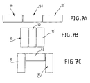
figures 7A à 7C sont des schémas illustrant différentes configurations d'assemblage, - la
figure 8 est une vue en perspective illustrant une plateforme selon une variante de l'invention avec un garde-corps, - la
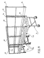
figure 9 est une vue en perspective illustrant une plateforme selon une autre variante de l'invention avec un garde corps, - la
figure 10 est vue de dessous illustrant un coin d'une autre variante d'un module du second type, - la
figure 11A est une vue en perspective illustrant une variante d'un crochet pour assembler deux modules, et - la
figure 11B est une vue en perspective illustrant une autre variante d'un crochet pour assembler deux modules. - Sur la
figure 1 , on a représenté un module 10 d'un premier type comprenant un plancher 12 et deux supports 14. - Le plancher 12 a une forme rectangulaire. A titre indicatif, le plancher a une longueur de l'ordre de 2 m et une largeur de l'ordre de 0,8 m.
- Pour la suite de la description, on entend par direction longitudinale, la direction qui correspond à la longueur du plancher alors que la direction transversale correspond à la largeur.
- Selon un mode de réalisation, le plancher 12 est réalisé à partir d'une tôle dont les bords sont pliés à 90° de manière à former des chants longitudinaux 16 et des chants transversaux 18.
- Ainsi, le plancher et les chants transversaux et longitudinaux forment une cavité dans laquelle peuvent être disposés les supports 14 rabattus, comme cela sera expliqué ultérieurement. Lorsque les supports 14 sont rabattus, le module 10 a une forme parallélépipédique de manière à ce que les modules puissent être aisément empilés les uns sur les autres.
- Selon un mode de réalisation, chaque support 14 comprend deux montants 20 reliés par deux traverses 22, chacun desdits montants 20 ayant une première extrémité pivotante par rapport à une platine 24 solidaire du plancher selon un axe de pivotement 25 orienté selon la direction transversale.
- De préférence, les montants sont réglables en longueur. Ainsi, chaque montant comprend deux tubes qui coulissent l'un dans l'autre, le premier étant pivotant par rapport à la platine, le second coulissant dans le premier et comprenant au niveau de son extrémité sortante une chape 26 supportant une roulette 28. Avantageusement, la roulette 28 est orientable et peut pivoter autour d'un axe parallèle à la direction du montant comme matérialisé par la double flèche 30.
- Pour obtenir le réglage en longueur du montant, le premier tube comprend un seul trou traversant orienté selon la direction transversale, le second tube comprenant une succession de trous adaptés pour coopérer avec celui du premier tube. En complément, une goupille prévue pour se loger dans le trou du premier tube et l'un des trous du second tube permet d'empêcher le coulissement du second tube dans le premier tube et ainsi de régler la longueur du montant.
- De préférence, les tubes ont des sections carrées.
- Selon un mode de réalisation, une platine 24 comprend un tube creux 32 avec une section carrée, orienté perpendiculairement au plancher 12, ainsi que deux ailes 34 de part et d'autre dudit tube creux 32 pour assurer sa liaison avec un chant longitudinal 16 à proximité d'un chant transversal 18. La liaison entre la platine 24 et le chant longitudinal 16 est assurée par tous moyens appropriés, par exemple par rivetage (quatre rivets selon l'exemple illustré).
- Une découpe 36 est réalisée au niveau du plancher 12 de manière à rendre accessible le tube creux 32 de la platine depuis le dessus du plancher comme illustré sur la
figure 3 . - Pour assurer la liaison pivotante entre un montant et la platine correspondante, on peut prévoir une tige ou un tube assurant la fonction d'axe de rotation.
- Comme illustré sur la
figure 1 , chaque module 10 du premier type comprend deux supports, pivotant chacun selon un axe de rotation transversal disposé à proximité d'un chant transversal. - Chaque support peut occuper deux états, un premier état déployé, comme illustré à gauche de la
figure 1 , dans lequel le support est disposé à 90° par rapport au plancher, et un second état rabattu, comme illustré à droite de lafigure 1 , dans lequel le support est disposé parallèlement au plancher. - Chaque support 14 dispose d'un jambage 38 pour le maintenir à l'état déployé.
- Selon un mode de réalisation, un jambage 38 comprend un premier fourreau 40 qui peut pivoter sur une traverse 22 du support correspondant, notamment la traverse la plus éloignée de l'axe de pivotement du support, une tige 42 s'étendant selon la direction longitudinale et dont une première extrémité est liée au premier fourreau 40, un second fourreau 44 dans lequel peut coulisser la tige 42, un troisième fourreau 46 solidaire du second fourreau 44 apte à pivoter sur un axe 48 s'étendant selon la direction transversale et dont les extrémités sont solidaires des chants longitudinaux du plancher.
- Comme pour les montants, une goupille est prévue pour limiter le mouvement de coulissement de la tige 42 dans le second fourreau 44 et maintenir ainsi le support à l'état déployé.
- Avantageusement, le même axe 48 est utilisé pour les deux ensembles jambage/support d'un même module 10.
- D'autres modes de réalisation pourraient être envisagés pour les supports et les jambages.
- Sur la
figure 2 , on a représenté un module 50 d'un second type. Contrairement à un module 10 du premier type, il ne comprend ni support, ni jambage. Il comprend uniquement un plancher 12 et des platines 24 avec chacune un tube creux 32 accessible depuis le dessus du plancher grâce à une découpe 36. - Les modules 50 du second type ont des dimensions analogues aux modules 10 du premier type.
- Pour obtenir une plateforme selon l'invention, on peut utiliser un ou plusieurs modules 10 du premier type accolés les uns aux autres.
- De préférence, on relie deux modules 10 du premier type grâce à un module 50 du second type.
- Les éléments étant liés les uns aux autres, on peut déplacer l'ensemble des modules liés en agissant sur un seul module.
- A cet effet, la plateforme comprend des crochets de liaison 52 illustrés sur les
figures 5, 6 ,11A et 11B . - Selon un premier mode de réalisation illustré sur la
figure 5 , un crochet de liaison 52 comprend une platine en forme de 5 avec une partie centrale 54 plane prolongée à une première extrémité par une première aile 56 pliée à 90° selon une première direction et à une seconde extrémité par une seconde aile 58 pliée à 90° selon une seconde direction opposée à la première direction. Le fait de prévoir une partie centrale 54 plane sous forme d'une plaque permet de limiter les mouvements relatifs entre modules lorsqu'ils sont assemblés. Le fait de prévoir de part et d'autre de la partie centrale des ailes égales planes sous forme de plaque assure une meilleure stabilité. - Pour assurer la liaison entre deux modules, le crochet 52 comprend d'une part au niveau de la première aile 56 un axe 60 sensiblement parallèle à la partie centrale 54 orienté vers la seconde extrémité de ladite partie centrale 54 susceptible de coopérer avec un orifice 62 prévu au niveau de la surface supérieure du plancher d'un module 10 du premier type, de préférence à équidistance des chants, et d'autre part, au niveau de la seconde aile 58 un tube 64 sensiblement parallèle à la partie centrale 54 orienté vers la première extrémité de ladite partie centrale 54 susceptible de coopérer avec un tube creux 66 dont la section est adaptée à celle du tube 64 afin que ce dernier coulisse dans ledit tube creux 66 quasiment sans jeu. De préférence, le tube 64 a une section carrée.
- Selon la variante illustrée sur la
figure 4 , le tube 64 et l'axe 60 sont disposés dans un plan perpendiculaire au plan de la partie centrale 54. - Selon la variante illustrée sur la
figure 4 , le tube creux 66 est disposé à équidistance du chant longitudinal et du chant transversal et solidarisé à une platine 24. - Pour obtenir un assemblage sûr, la distance entre le tube 64 et la partie centrale 54 notée E sur la
figure 5 est sensiblement égale à la distance séparant la face extérieure du chant longitudinal ou du chant transversal et la face intérieure du tube creux 66. De la même manière, la distance entre l'axe 60 et la partie centrale 54, notée E1 sur lafigure 5 est sensiblement égale à la distance séparant l'axe de l'orifice 62 du chant longitudinal et du chant transversal. - En complément, la longueur de la partie centrale 54 correspond sensiblement à la hauteur d'un chant.
- De préférence, un tube creux 66 est prévu au niveau de chaque angle d'un module 50 du second type.
- Un orifice 62 est prévu au niveau de chaque angle d'un module 10 du premier type. D'autres orifices 62 peuvent être prévus entre ceux ménagés au niveau des angles selon la direction longitudinale pour associer un module 10 et un module 50 en L ou en T.
- Pour assurer la liaison entre un module 10 du premier type et un module 50 du second type, on utilise deux crochets 52. Dans un premier temps, les tubes 64 des deux crochets sont insérés dans les tubes en creux 66 du second module puis les axes 60 des crochets 52 sont insérés dans les orifices 62 du premier module 10.
- Des crochets de liaison 52 peuvent être utilisés pour assurer la liaison entre deux modules 10 du premier type. Dans ce cas, au moins l'un des deux modules 10 comprend des tubes creux 66 au niveau des platines 24.
- Une goupille ou tout autre élément analogue peut être utilisée pour assurer une liaison entre le crochet 52 et le tube creux 66.
- Selon l'invention, on note que les crochets 52 sont disposés entre les modules et qu'aucun élément de liaison ne vient en saillie par rapport aux modules.
- Selon une autre variante illustrée sur la
figure 10 , le tube creux 66 peut être fixé (par soudage par exemple) à la platine 24 au niveau de la face opposée à celle plaquée contre un chant longitudinal. Selon cette variante, seuls les modules du second type comprennent un tube creux 66. - Dans ce cas, le tube 64 est déporté par rapport à l'axe 60 comme illustré sur les
figures 11A et 11B afin que l'orifice 62 apte à recevoir l'axe 60 soit décalé par rapport au tube creux 32 et que l'aile 58 n'obture pas le tube creux 32. - Ainsi, le tube 64 peut être décalé d'un premier côté comme illustré sur la
figure 11A et d'un autre côté comme illustré sur lafigure 11B . - Selon un mode d'assemblage, on utilise pour un module du second type au niveau d'un même chant longitudinal à une première extrémité un crochet 52 illustré sur la
figure 11A et à l'autre extrémité un crochet 52 illustré sur lafigure 11B de manière à disposer les axes 60 des crochets 52 décalés vers l'intérieur par rapport aux tubes 64 desdits crochets 52. - Comme illustré sur les
figures 7A à 7C , une plateforme est obtenue à partir d'un assemblage d'un module 50 du second type intercalé entre deux modules 10, 10' du premier type. Selon des configurations plus complexes, un autre module du second type peut être intercalé entre le module 10 ou 10' du premier type et un autre module du premier type. - Selon un mode d'assemblage illustré sur la
figure 7A , les modules 10, 50 et 10' sont disposés bout à bout, les chants transversaux de deux modules adjacents étant plaqués l'un contre l'autre. - Selon un autre mode d'assemblage illustré sur la
figure 7B , les modules 10, 50 et 10' sont disposés les uns contre les autres, les chants longitudinaux de deux modules adjacents étant plaqués l'un contre l'autre. - Selon un autre mode d'assemblage illustré sur la
figure 7C , les modules 10 et 10' sont disposés parallèlement et le module 50 est intercalé entre les modules 10 et 10' et disposé perpendiculairement auxdits modules 10 et 10'. - Bien entendu, l'invention n'est pas limitée à ces modes d'assemblage.
- Selon une autre caractéristique de l'invention, la plateforme comprend un garde-corps disposé au niveau de la périphérie de ladite plateforme.
- Ce garde-corps comprend des rambardes 68 dont la longueur correspond à la longueur d'un module 10 ou 50. Chaque rambarde 68 comprend d'une part deux montants dont les extrémités inférieures sont susceptibles de s'emmancher dans les tubes creux 32 des platines 24 accessibles depuis le dessus du plancher, et d'autre part, des traverses sensiblement horizontales reliant les deux montants.
- Le garde corps peut comprendre également des montants isolés ou poteau 70 dont les extrémités inférieures sont susceptibles de s'emmancher dans les tubes creux 32 des platines 24 accessibles depuis le dessus du plancher.
- Le garde-corps comprend également des portillons 72 comportant deux montants verticaux reliés par des traverses. Chaque portillon 72 peut être relié à une rambarde 68 par des moyens d'articulation autorisant un pivotement selon un axe vertical dudit portillon par rapport à la rambarde 68.
- En complément, chaque portillon 72 comprend des moyens pour empêcher son pivotement, par exemple un loquet.
- Selon un mode de réalisation, chaque portillon 72 comprend au niveau d'un montant deux paumelles 74, chacune comportant un axe orienté vers le bas, coopérant avec deux fourreaux (ou deux pattes avec chacune un orifice) solidaires d'un montant d'une rambarde 68 de manière à former deux charnières. Chaque portillon 72 comprend au niveau de l'autre montant au moins une paumelle 76, comportant un axe orienté vers le bas et coopérant avec au moins un fourreau (ou au moins une patte avec un orifice) solidaire d'un montant isolé 70 ou d'un montant d'une rambarde 68 de manière à former un loquet.
- Selon cet agencement, l'axe de la paumelle 76 utilisée comme loquet est plus court que les axes des paumelles 74 utilisées comme charnière. Ainsi, pour ouvrir ou fermer le portillon, l'utilisateur doit légèrement soulever le portillon de manière à engager ou dégager l'axe d'une paumelle 76 du fourreau correspondant. Dans la mesure où les axes des paumelles 74 sont plus longs, le portillon est toujours articulé.
- Selon un mode de réalisation, un montant isolé ou poteau 70 comprend au moins un fourreau pour recevoir un axe d'une paumelle 74 ou 76.
- Selon un mode de réalisation, une rambarde 68 comprend au niveau de chaque montant deux pattes avec chacune un orifice, une en bas et une en haut, lesdites pattes étant rapportées au niveau de chaque montant à la face opposée à celle liée aux traverses des rambardes.
- Selon un mode de réalisation, chaque montant isolé ou poteau 70 comprend deux pattes avec chacune un orifice, une en bas et une en haut.
- Selon un mode de réalisation, chaque portillon comprend au niveau d'un premier montant deux paumelles 76 et au niveau de l'autre montant deux paumelles 74.
Claims (7)
- Plateforme modulable comprenant au moins deux modules comportant chacun un plancher (12) avec des chants longitudinaux (16) et des chants transversaux (18) et deux supports (14) ainsi que deux crochets de liaison (52) assurant la liaison entre deux modules adjacents, un crochet de liaison (52) ayant une forme de 5 et comprenant une partie centrale (54), au niveau d'une première extrémité (56) de ladite partie centrale (54) un axe (60) sensiblement parallèle à la partie centrale (54) orienté vers une seconde extrémité de ladite partie centrale (54) susceptible de coopérer avec un orifice (62) prévu au niveau de la surface supérieure du plancher d'un module, et d'autre part, au niveau de la seconde extrémité (58) de ladite partie centrale (54) un axe (64) sensiblement parallèle à la partie centrale (54) orienté vers la première extrémité de ladite partie centrale (54) susceptible de coopérer avec un tube creux (66) solidaire du plancher d'un module dont la section est adaptée à celle de l'axe (64), caractérisé en ce que la partie centrale (54) de chaque crochet de liaison (52) est plane et prolongée à une première extrémité par une première aile (56) pliée à 90° selon une première direction et à une seconde extrémité par une seconde aile (58) pliée à 90° selon une seconde direction opposée à la première direction.
- Plateforme modulable selon la revendication 1, caractérisée en ce que l'orifice (62) est ménagé à équidistance du chant longitudinal et du chant transversal et en ce que la distance entre l'axe (60) et la partie centrale (54) est sensiblement égale à la distance séparant l'axe de l'orifice (62) du chant longitudinal et du chant transversal.
- Plateforme modulable selon la revendication 1 ou 2, caractérisée en ce que le tube creux (66) est à équidistance du chant longitudinal et du chant transversal et en ce que la distance entre l'axe (64) et la partie centrale (54) est sensiblement égale à la distance séparant la face extérieure du chant longitudinal ou du chant transversal et la face intérieure du tube creux (66).
- Plateforme modulable selon l'une quelconque des revendications précédentes, caractérisée en ce que chaque module comprend au niveau des angles, sous le plancher, une platine (24) avec un tube creux (32) orienté perpendiculairement audit plancher (12) et accessible depuis le dessus du plancher (12) grâce à une découpe (36) ménagée dans le plancher (12).
- Plateforme modulable selon la revendication 4, caractérisée en ce que certains modules comprennent deux supports (14) montés pivotants chacun par rapport à une platine (24) de manière à occuper un premier état déployé dans lequel ils sont disposés perpendiculairement au plancher (12) et un second état rabattu dans lequel ils sont disposés parallèlement au plancher (12).
- Plateforme modulable selon la revendication 4 ou 5, caractérisée en ce qu'elle comprend des rambardes (68) avec deux montants reliés par des traverses, les extrémités inférieures desdits montants étant susceptibles de s'emmancher dans les tubes creux (32) des platines (24) et au moins un portillon (72) relié à une rambarde (68) par des moyens d'articulation autorisant un pivotement selon un axe vertical dudit portillon par rapport à la rambarde (68).
- Plateforme modulable selon la revendication 6, caractérisée en ce qu'un portillon (72) comprend au niveau d'un montant deux paumelles (74), chacune comportant un axe orienté vers le bas, coopérant avec deux fourreaux ou deux pattes avec chacune un orifice solidaires d'un montant d'une rambarde (68) de manière à former deux charnières et au niveau de l'autre montant au moins une paumelle (76) comportant un axe orienté vers le bas et coopérant avec au moins un fourreau ou une patte avec un orifice solidaire montant d'une rambarde (68) de manière à former un loquet, l'axe de la paumelle (76) utilisée comme loquet étant plus court que les axes des paumelles (74) utilisées comme charnière.
Applications Claiming Priority (1)
| Application Number | Priority Date | Filing Date | Title |
|---|---|---|---|
| FR0950712A FR2941729B1 (fr) | 2009-02-05 | 2009-02-05 | Plateforme modulable. |
Publications (3)
| Publication Number | Publication Date |
|---|---|
| EP2216464A2 true EP2216464A2 (fr) | 2010-08-11 |
| EP2216464A3 EP2216464A3 (fr) | 2014-11-05 |
| EP2216464B1 EP2216464B1 (fr) | 2016-04-20 |
Family
ID=40957742
Family Applications (1)
| Application Number | Title | Priority Date | Filing Date |
|---|---|---|---|
| EP10305121.5A Active EP2216464B1 (fr) | 2009-02-05 | 2010-02-05 | Plateforme modulable |
Country Status (3)
| Country | Link |
|---|---|
| EP (1) | EP2216464B1 (fr) |
| ES (1) | ES2582532T3 (fr) |
| FR (1) | FR2941729B1 (fr) |
Cited By (4)
| Publication number | Priority date | Publication date | Assignee | Title |
|---|---|---|---|---|
| KR101353089B1 (ko) * | 2012-03-13 | 2014-01-20 | 김현식 | 고소작업대에서 발판의 연결구조 |
| KR101386371B1 (ko) * | 2013-06-21 | 2014-04-16 | 김현식 | 발판 연결장치와, 발판 연결장치가 구비된 발판 및 발판구조체 |
| JP2020143477A (ja) * | 2019-03-05 | 2020-09-10 | ジー・オー・ピー株式会社 | 手摺および作業台システム |
| GB2584880A (en) * | 2019-06-19 | 2020-12-23 | Oxford Safety Components | Support apparatus |
Families Citing this family (2)
| Publication number | Priority date | Publication date | Assignee | Title |
|---|---|---|---|---|
| US20250075517A1 (en) * | 2021-04-23 | 2025-03-06 | Grady F. Smith & Co., Inc. D/B/A Scaffoldmart | Guard Rail for Multifunction Scaffold |
| GB202418204D0 (en) * | 2024-12-12 | 2025-01-29 | Kiverco | A component for forming a walkway, a walkway, and a kit of parts |
Citations (1)
| Publication number | Priority date | Publication date | Assignee | Title |
|---|---|---|---|---|
| AU503902B2 (en) | 1975-03-14 | 1979-09-27 | Comalco Prod | Scaffold plank |
Family Cites Families (2)
| Publication number | Priority date | Publication date | Assignee | Title |
|---|---|---|---|---|
| JPH11210221A (ja) * | 1998-01-29 | 1999-08-03 | Hitachi Plant Eng & Constr Co Ltd | 防塵装置付き作業足場 |
| JP3790391B2 (ja) * | 1999-09-01 | 2006-06-28 | 株式会社竹中工務店 | 脚立連結装置 |
-
2009
- 2009-02-05 FR FR0950712A patent/FR2941729B1/fr not_active Expired - Fee Related
-
2010
- 2010-02-05 EP EP10305121.5A patent/EP2216464B1/fr active Active
- 2010-02-05 ES ES10305121.5T patent/ES2582532T3/es active Active
Patent Citations (1)
| Publication number | Priority date | Publication date | Assignee | Title |
|---|---|---|---|---|
| AU503902B2 (en) | 1975-03-14 | 1979-09-27 | Comalco Prod | Scaffold plank |
Cited By (7)
| Publication number | Priority date | Publication date | Assignee | Title |
|---|---|---|---|---|
| KR101353089B1 (ko) * | 2012-03-13 | 2014-01-20 | 김현식 | 고소작업대에서 발판의 연결구조 |
| KR101386371B1 (ko) * | 2013-06-21 | 2014-04-16 | 김현식 | 발판 연결장치와, 발판 연결장치가 구비된 발판 및 발판구조체 |
| WO2014204283A1 (fr) * | 2013-06-21 | 2014-12-24 | Kim Hyun-Sik | Dispositif de liaison de prise de pied, prise de pied ayant un dispositif de liaison de prise de pied, et structure de prise de pied |
| JP2020143477A (ja) * | 2019-03-05 | 2020-09-10 | ジー・オー・ピー株式会社 | 手摺および作業台システム |
| JP2023166587A (ja) * | 2019-03-05 | 2023-11-21 | ジー・オー・ピー株式会社 | 手摺および作業台システム |
| GB2584880A (en) * | 2019-06-19 | 2020-12-23 | Oxford Safety Components | Support apparatus |
| WO2020254779A1 (fr) * | 2019-06-19 | 2020-12-24 | Oxford Safety Components Limited | Appareil de support |
Also Published As
| Publication number | Publication date |
|---|---|
| EP2216464A3 (fr) | 2014-11-05 |
| FR2941729B1 (fr) | 2015-07-17 |
| EP2216464B1 (fr) | 2016-04-20 |
| FR2941729A1 (fr) | 2010-08-06 |
| ES2582532T3 (es) | 2016-09-13 |
Similar Documents
| Publication | Publication Date | Title |
|---|---|---|
| EP2216464B1 (fr) | Plateforme modulable | |
| EP3192942B1 (fr) | Echafaudage comportant deux ensembles d'echelle maintenus distants l'un de l'autre par une base pliante pre-montee | |
| FR3058432B1 (fr) | Perfectionnement aux tours d'etaiement. | |
| EP3192940B1 (fr) | Echafaudage comportant deux echelles deployables et supportant un garde-corps | |
| FR3046622A1 (fr) | Echafaudage comportant un garde-corps abaissable. | |
| FR2929304A1 (fr) | Dispositif d'echafaudage repliable et a hauteur de travail modulable | |
| FR2939820A1 (fr) | Equipement d'extension laterale pour plateforme porte banches | |
| FR2775314A1 (fr) | Verrou automatique pour volet roulant | |
| FR2975116A1 (fr) | Echafaudage pliant | |
| FR2977501A1 (fr) | Structure d'escalade autoportee, pliable, a double mur et a geometrie variable | |
| EP0468907A1 (fr) | Passerelle-support repliable pour banches de coffrage | |
| WO1996002716A1 (fr) | Escalier a configuration variable | |
| EP2706166B1 (fr) | Tour d'étaiement modulaire pour le génie civil et le bâtiment | |
| FR3046619A1 (fr) | Echafaudage comportant deux ensembles d'echelle en plusieurs parties coulissantes les unes par rapport aux autres. | |
| FR2990985A1 (fr) | Echelle de toit notamment pour couvreurs | |
| FR2519243A1 (fr) | Rayonnage | |
| EP2551442A1 (fr) | Dispositif d'accès en hauteur | |
| EP0580456B1 (fr) | Echafaudage | |
| EP0282385B1 (fr) | Dispositif d'ancrage sur chevrons pour travaux de toiture | |
| FR2990986A1 (fr) | Echelle de toit, notamment pour couvreur | |
| FR2777929A1 (fr) | Plate-forme telescopique | |
| FR2804095A1 (fr) | Meuble de stockage dynamique | |
| EP2174756B1 (fr) | Paire de chevalets pliants | |
| FR2716491A1 (fr) | Echelle, notamment pour travaux domestiques. | |
| FR2903717A1 (fr) | Marchepied amovible et autoverrouillable |
Legal Events
| Date | Code | Title | Description |
|---|---|---|---|
| PUAI | Public reference made under article 153(3) epc to a published international application that has entered the european phase |
Free format text: ORIGINAL CODE: 0009012 |
|
| AK | Designated contracting states |
Kind code of ref document: A2 Designated state(s): AT BE BG CH CY CZ DE DK EE ES FI FR GB GR HR HU IE IS IT LI LT LU LV MC MK MT NL NO PL PT RO SE SI SK SM TR |
|
| PUAL | Search report despatched |
Free format text: ORIGINAL CODE: 0009013 |
|
| AK | Designated contracting states |
Kind code of ref document: A3 Designated state(s): AT BE BG CH CY CZ DE DK EE ES FI FR GB GR HR HU IE IS IT LI LT LU LV MC MK MT NL NO PL PT RO SE SI SK SM TR |
|
| RIC1 | Information provided on ipc code assigned before grant |
Ipc: E04G 7/28 20060101ALI20141001BHEP Ipc: E04G 1/15 20060101AFI20141001BHEP Ipc: E04G 5/08 20060101ALI20141001BHEP |
|
| 17P | Request for examination filed |
Effective date: 20150416 |
|
| RBV | Designated contracting states (corrected) |
Designated state(s): AT BE BG CH CY CZ DE DK EE ES FI FR GB GR HR HU IE IS IT LI LT LU LV MC MK MT NL NO PL PT RO SE SI SK SM TR |
|
| REG | Reference to a national code |
Ref country code: DE Ref legal event code: R079 Ref document number: 602010032440 Country of ref document: DE Free format text: PREVIOUS MAIN CLASS: E04G0001150000 Ipc: E04G0001340000 |
|
| GRAP | Despatch of communication of intention to grant a patent |
Free format text: ORIGINAL CODE: EPIDOSNIGR1 |
|
| INTG | Intention to grant announced |
Effective date: 20150914 |
|
| RIC1 | Information provided on ipc code assigned before grant |
Ipc: E04G 7/28 20060101ALI20150904BHEP Ipc: E04G 5/14 20060101ALI20150904BHEP Ipc: E04G 1/24 20060101ALI20150904BHEP Ipc: E04G 1/34 20060101AFI20150904BHEP |
|
| GRAS | Grant fee paid |
Free format text: ORIGINAL CODE: EPIDOSNIGR3 |
|
| GRAA | (expected) grant |
Free format text: ORIGINAL CODE: 0009210 |
|
| AK | Designated contracting states |
Kind code of ref document: B1 Designated state(s): AT BE BG CH CY CZ DE DK EE ES FI FR GB GR HR HU IE IS IT LI LT LU LV MC MK MT NL NO PL PT RO SE SI SK SM TR |
|
| REG | Reference to a national code |
Ref country code: GB Ref legal event code: FG4D Free format text: NOT ENGLISH |
|
| REG | Reference to a national code |
Ref country code: CH Ref legal event code: EP |
|
| REG | Reference to a national code |
Ref country code: AT Ref legal event code: REF Ref document number: 792634 Country of ref document: AT Kind code of ref document: T Effective date: 20160515 |
|
| REG | Reference to a national code |
Ref country code: IE Ref legal event code: FG4D Free format text: LANGUAGE OF EP DOCUMENT: FRENCH |
|
| REG | Reference to a national code |
Ref country code: DE Ref legal event code: R096 Ref document number: 602010032440 Country of ref document: DE |
|
| REG | Reference to a national code |
Ref country code: CH Ref legal event code: NV Representative=s name: BUGNION S.A., CH |
|
| REG | Reference to a national code |
Ref country code: LT Ref legal event code: MG4D |
|
| REG | Reference to a national code |
Ref country code: ES Ref legal event code: FG2A Ref document number: 2582532 Country of ref document: ES Kind code of ref document: T3 Effective date: 20160913 |
|
| REG | Reference to a national code |
Ref country code: AT Ref legal event code: MK05 Ref document number: 792634 Country of ref document: AT Kind code of ref document: T Effective date: 20160420 |
|
| REG | Reference to a national code |
Ref country code: NL Ref legal event code: MP Effective date: 20160420 |
|
| PG25 | Lapsed in a contracting state [announced via postgrant information from national office to epo] |
Ref country code: FI Free format text: LAPSE BECAUSE OF FAILURE TO SUBMIT A TRANSLATION OF THE DESCRIPTION OR TO PAY THE FEE WITHIN THE PRESCRIBED TIME-LIMIT Effective date: 20160420 Ref country code: NL Free format text: LAPSE BECAUSE OF FAILURE TO SUBMIT A TRANSLATION OF THE DESCRIPTION OR TO PAY THE FEE WITHIN THE PRESCRIBED TIME-LIMIT Effective date: 20160420 Ref country code: NO Free format text: LAPSE BECAUSE OF FAILURE TO SUBMIT A TRANSLATION OF THE DESCRIPTION OR TO PAY THE FEE WITHIN THE PRESCRIBED TIME-LIMIT Effective date: 20160720 Ref country code: LT Free format text: LAPSE BECAUSE OF FAILURE TO SUBMIT A TRANSLATION OF THE DESCRIPTION OR TO PAY THE FEE WITHIN THE PRESCRIBED TIME-LIMIT Effective date: 20160420 Ref country code: PL Free format text: LAPSE BECAUSE OF FAILURE TO SUBMIT A TRANSLATION OF THE DESCRIPTION OR TO PAY THE FEE WITHIN THE PRESCRIBED TIME-LIMIT Effective date: 20160420 |
|
| PG25 | Lapsed in a contracting state [announced via postgrant information from national office to epo] |
Ref country code: GR Free format text: LAPSE BECAUSE OF FAILURE TO SUBMIT A TRANSLATION OF THE DESCRIPTION OR TO PAY THE FEE WITHIN THE PRESCRIBED TIME-LIMIT Effective date: 20160721 Ref country code: HR Free format text: LAPSE BECAUSE OF FAILURE TO SUBMIT A TRANSLATION OF THE DESCRIPTION OR TO PAY THE FEE WITHIN THE PRESCRIBED TIME-LIMIT Effective date: 20160420 Ref country code: SE Free format text: LAPSE BECAUSE OF FAILURE TO SUBMIT A TRANSLATION OF THE DESCRIPTION OR TO PAY THE FEE WITHIN THE PRESCRIBED TIME-LIMIT Effective date: 20160420 Ref country code: LV Free format text: LAPSE BECAUSE OF FAILURE TO SUBMIT A TRANSLATION OF THE DESCRIPTION OR TO PAY THE FEE WITHIN THE PRESCRIBED TIME-LIMIT Effective date: 20160420 Ref country code: AT Free format text: LAPSE BECAUSE OF FAILURE TO SUBMIT A TRANSLATION OF THE DESCRIPTION OR TO PAY THE FEE WITHIN THE PRESCRIBED TIME-LIMIT Effective date: 20160420 Ref country code: PT Free format text: LAPSE BECAUSE OF FAILURE TO SUBMIT A TRANSLATION OF THE DESCRIPTION OR TO PAY THE FEE WITHIN THE PRESCRIBED TIME-LIMIT Effective date: 20160822 |
|
| REG | Reference to a national code |
Ref country code: DE Ref legal event code: R097 Ref document number: 602010032440 Country of ref document: DE |
|
| PG25 | Lapsed in a contracting state [announced via postgrant information from national office to epo] |
Ref country code: SK Free format text: LAPSE BECAUSE OF FAILURE TO SUBMIT A TRANSLATION OF THE DESCRIPTION OR TO PAY THE FEE WITHIN THE PRESCRIBED TIME-LIMIT Effective date: 20160420 Ref country code: DK Free format text: LAPSE BECAUSE OF FAILURE TO SUBMIT A TRANSLATION OF THE DESCRIPTION OR TO PAY THE FEE WITHIN THE PRESCRIBED TIME-LIMIT Effective date: 20160420 Ref country code: RO Free format text: LAPSE BECAUSE OF FAILURE TO SUBMIT A TRANSLATION OF THE DESCRIPTION OR TO PAY THE FEE WITHIN THE PRESCRIBED TIME-LIMIT Effective date: 20160420 Ref country code: CZ Free format text: LAPSE BECAUSE OF FAILURE TO SUBMIT A TRANSLATION OF THE DESCRIPTION OR TO PAY THE FEE WITHIN THE PRESCRIBED TIME-LIMIT Effective date: 20160420 Ref country code: EE Free format text: LAPSE BECAUSE OF FAILURE TO SUBMIT A TRANSLATION OF THE DESCRIPTION OR TO PAY THE FEE WITHIN THE PRESCRIBED TIME-LIMIT Effective date: 20160420 |
|
| PLBE | No opposition filed within time limit |
Free format text: ORIGINAL CODE: 0009261 |
|
| REG | Reference to a national code |
Ref country code: FR Ref legal event code: PLFP Year of fee payment: 8 |
|
| STAA | Information on the status of an ep patent application or granted ep patent |
Free format text: STATUS: NO OPPOSITION FILED WITHIN TIME LIMIT |
|
| PG25 | Lapsed in a contracting state [announced via postgrant information from national office to epo] |
Ref country code: SM Free format text: LAPSE BECAUSE OF FAILURE TO SUBMIT A TRANSLATION OF THE DESCRIPTION OR TO PAY THE FEE WITHIN THE PRESCRIBED TIME-LIMIT Effective date: 20160420 |
|
| 26N | No opposition filed |
Effective date: 20170123 |
|
| PG25 | Lapsed in a contracting state [announced via postgrant information from national office to epo] |
Ref country code: BE Free format text: LAPSE BECAUSE OF NON-PAYMENT OF DUE FEES Effective date: 20170228 Ref country code: SI Free format text: LAPSE BECAUSE OF FAILURE TO SUBMIT A TRANSLATION OF THE DESCRIPTION OR TO PAY THE FEE WITHIN THE PRESCRIBED TIME-LIMIT Effective date: 20160420 |
|
| PG25 | Lapsed in a contracting state [announced via postgrant information from national office to epo] |
Ref country code: MC Free format text: LAPSE BECAUSE OF FAILURE TO SUBMIT A TRANSLATION OF THE DESCRIPTION OR TO PAY THE FEE WITHIN THE PRESCRIBED TIME-LIMIT Effective date: 20160420 |
|
| REG | Reference to a national code |
Ref country code: IE Ref legal event code: MM4A |
|
| PG25 | Lapsed in a contracting state [announced via postgrant information from national office to epo] |
Ref country code: LU Free format text: LAPSE BECAUSE OF NON-PAYMENT OF DUE FEES Effective date: 20170205 |
|
| REG | Reference to a national code |
Ref country code: FR Ref legal event code: PLFP Year of fee payment: 9 Ref country code: BE Ref legal event code: MM Effective date: 20170228 |
|
| PG25 | Lapsed in a contracting state [announced via postgrant information from national office to epo] |
Ref country code: IE Free format text: LAPSE BECAUSE OF NON-PAYMENT OF DUE FEES Effective date: 20170205 |
|
| PG25 | Lapsed in a contracting state [announced via postgrant information from national office to epo] |
Ref country code: MT Free format text: LAPSE BECAUSE OF FAILURE TO SUBMIT A TRANSLATION OF THE DESCRIPTION OR TO PAY THE FEE WITHIN THE PRESCRIBED TIME-LIMIT Effective date: 20160420 |
|
| PG25 | Lapsed in a contracting state [announced via postgrant information from national office to epo] |
Ref country code: HU Free format text: LAPSE BECAUSE OF FAILURE TO SUBMIT A TRANSLATION OF THE DESCRIPTION OR TO PAY THE FEE WITHIN THE PRESCRIBED TIME-LIMIT; INVALID AB INITIO Effective date: 20100205 |
|
| PG25 | Lapsed in a contracting state [announced via postgrant information from national office to epo] |
Ref country code: BG Free format text: LAPSE BECAUSE OF FAILURE TO SUBMIT A TRANSLATION OF THE DESCRIPTION OR TO PAY THE FEE WITHIN THE PRESCRIBED TIME-LIMIT Effective date: 20160420 |
|
| PG25 | Lapsed in a contracting state [announced via postgrant information from national office to epo] |
Ref country code: CY Free format text: LAPSE BECAUSE OF NON-PAYMENT OF DUE FEES Effective date: 20160420 |
|
| PG25 | Lapsed in a contracting state [announced via postgrant information from national office to epo] |
Ref country code: MK Free format text: LAPSE BECAUSE OF FAILURE TO SUBMIT A TRANSLATION OF THE DESCRIPTION OR TO PAY THE FEE WITHIN THE PRESCRIBED TIME-LIMIT Effective date: 20160420 |
|
| PG25 | Lapsed in a contracting state [announced via postgrant information from national office to epo] |
Ref country code: TR Free format text: LAPSE BECAUSE OF FAILURE TO SUBMIT A TRANSLATION OF THE DESCRIPTION OR TO PAY THE FEE WITHIN THE PRESCRIBED TIME-LIMIT Effective date: 20160420 |
|
| PGFP | Annual fee paid to national office [announced via postgrant information from national office to epo] |
Ref country code: GB Payment date: 20200206 Year of fee payment: 11 |
|
| PG25 | Lapsed in a contracting state [announced via postgrant information from national office to epo] |
Ref country code: IS Free format text: LAPSE BECAUSE OF FAILURE TO SUBMIT A TRANSLATION OF THE DESCRIPTION OR TO PAY THE FEE WITHIN THE PRESCRIBED TIME-LIMIT Effective date: 20160820 |
|
| GBPC | Gb: european patent ceased through non-payment of renewal fee |
Effective date: 20210205 |
|
| PG25 | Lapsed in a contracting state [announced via postgrant information from national office to epo] |
Ref country code: GB Free format text: LAPSE BECAUSE OF NON-PAYMENT OF DUE FEES Effective date: 20210205 |
|
| REG | Reference to a national code |
Ref country code: CH Ref legal event code: U11 Free format text: ST27 STATUS EVENT CODE: U-0-0-U10-U11 (AS PROVIDED BY THE NATIONAL OFFICE) Effective date: 20260301 |
|
| PGFP | Annual fee paid to national office [announced via postgrant information from national office to epo] |
Ref country code: ES Payment date: 20260319 Year of fee payment: 17 |
|
| PGFP | Annual fee paid to national office [announced via postgrant information from national office to epo] |
Ref country code: DE Payment date: 20260217 Year of fee payment: 17 |
|
| PGFP | Annual fee paid to national office [announced via postgrant information from national office to epo] |
Ref country code: IT Payment date: 20260227 Year of fee payment: 17 |
|
| PGFP | Annual fee paid to national office [announced via postgrant information from national office to epo] |
Ref country code: FR Payment date: 20260223 Year of fee payment: 17 |
|
| PGFP | Annual fee paid to national office [announced via postgrant information from national office to epo] |
Ref country code: CH Payment date: 20260301 Year of fee payment: 17 |