EP2216558A2 - Rouleau à réglage de la flexion - Google Patents
Rouleau à réglage de la flexion Download PDFInfo
- Publication number
- EP2216558A2 EP2216558A2 EP09177984A EP09177984A EP2216558A2 EP 2216558 A2 EP2216558 A2 EP 2216558A2 EP 09177984 A EP09177984 A EP 09177984A EP 09177984 A EP09177984 A EP 09177984A EP 2216558 A2 EP2216558 A2 EP 2216558A2
- Authority
- EP
- European Patent Office
- Prior art keywords
- roller according
- composite material
- end pieces
- axle
- axis
- Prior art date
- Legal status (The legal status is an assumption and is not a legal conclusion. Google has not performed a legal analysis and makes no representation as to the accuracy of the status listed.)
- Withdrawn
Links
Images

Classifications
-
- F—MECHANICAL ENGINEERING; LIGHTING; HEATING; WEAPONS; BLASTING
- F16—ENGINEERING ELEMENTS AND UNITS; GENERAL MEASURES FOR PRODUCING AND MAINTAINING EFFECTIVE FUNCTIONING OF MACHINES OR INSTALLATIONS; THERMAL INSULATION IN GENERAL
- F16C—SHAFTS; FLEXIBLE SHAFTS; ELEMENTS OR CRANKSHAFT MECHANISMS; ROTARY BODIES OTHER THAN GEARING ELEMENTS; BEARINGS
- F16C13/00—Rolls, drums, discs, or the like; Bearings or mountings therefor
- F16C13/02—Bearings
- F16C13/022—Bearings supporting a hollow roll mantle rotating with respect to a yoke or axle
- F16C13/024—Bearings supporting a hollow roll mantle rotating with respect to a yoke or axle adjustable for positioning, e.g. radial movable bearings for controlling the deflection along the length of the roll mantle
- F16C13/026—Bearings supporting a hollow roll mantle rotating with respect to a yoke or axle adjustable for positioning, e.g. radial movable bearings for controlling the deflection along the length of the roll mantle by fluid pressure
- F16C13/028—Bearings supporting a hollow roll mantle rotating with respect to a yoke or axle adjustable for positioning, e.g. radial movable bearings for controlling the deflection along the length of the roll mantle by fluid pressure with a plurality of supports along the length of the roll mantle, e.g. hydraulic jacks
-
- D—TEXTILES; PAPER
- D21—PAPER-MAKING; PRODUCTION OF CELLULOSE
- D21G—CALENDERS; ACCESSORIES FOR PAPER-MAKING MACHINES
- D21G1/00—Calenders; Smoothing apparatus
- D21G1/02—Rolls; Their bearings
- D21G1/0206—Controlled deflection rolls
- D21G1/0213—Controlled deflection rolls with deflection compensation means acting between the roller shell and its supporting member
- D21G1/022—Controlled deflection rolls with deflection compensation means acting between the roller shell and its supporting member the means using fluid pressure
Definitions
- the invention relates to a roller with a circumferential axis about a rotating jacket, which has at least one support element which can exert a force on the inner circumference of the shell, wherein the support member is supported on a non-rotating, the shell passing through axis.
- Such a roller is known in many variations. In the papermaking and converting industry to which reference should be made, such rolls are also referred to as deflection compensating rolls or simply as bending set rolls.
- the jacket is pressed against a counter-pressure element, which may for example also be a roller. Between the two forms a nip (a pressing surface), in which a running paper or board web can be treated under pressure.
- a counter-pressure element which may for example also be a roller.
- the rotating about a fixed axis jacket is made in such rolls of different materials.
- relatively soft, flexible coats are familiar, which rotate around the axis like a closed band and whose fictitious axis of rotation is not identical to the fixed axis got to.
- the number and shape of the support element or several support elements may differ greatly.
- the contact surface, which acts against the inner circumference of the shell for example, be concave or convex.
- the support members may be equipped with hydrostatic pockets to build up a uniform lubricating film between them and the jacket, or more (And this is particularly the case with press rolls, in which there is only a single so-called support shoe) only be provided with hydrodynamic action.
- the axis of a Biegeeinstellwalze is now commonly performed as a forging body to absorb the forces acting on the roller and dissipate the stiffening in which the roller is mounted.
- the forging of the axles made of steel is complex and the subsequent reworking of the forging body for introducing the required hydraulic supply for the support sources is associated with considerable costs.
- the axis In the DE 60 2005 003 460 T2 an alternative axle construction is presented.
- the axis In the first place to counteract vibration problems, but also used in the context of this invention to avoid the complex processing of forged axles, the axis consists at least in part of a fiber-reinforced composite material.
- An alternative construction, in which the axle body is glued in many layers of finished and provided with matrix material fiber mats, is at least as complex.
- the invention therefore has for its object to provide a Biegeeinstellwalze with an axle body, which is easier to manufacture.
- the object is achieved in that the main component of the axis of a cast or foamed composite material and the axis between two end pieces of a stiffer material than the composite material is arranged.
- a cast or foamed composite body can be produced in a single operation. If it hardens in a suitable mold or mold, it is immediately einbindbar between the two end pieces. An axle produced in this way is very inexpensive and quick to complete. The machining of axle bodies made of round steel or molded parts made of fiber-reinforced composite material is eliminated. It is preferred if the material according to the invention of a composite material which has a similar thermal expansion as steel and its modulus is significantly smaller than steel (about 5000 to 110000N / mm 2 ).
- the end pieces at the same time include the storable pins. In this way, you save yourself a further extension of the axis and the strength-considered complicated connection of separate storable pin to the end pieces.
- the composite material is poured or foamed in between the end pieces.
- Anchors may be provided on the end pieces to establish a thrust-free connection between the respective end piece and the axle by being enclosed by the cast or foamed composite material.
- at least one line a supply channel
- the hydraulic lines to the at least one support element are particularly easy to implement. For example, the necessary Pipes protected in the composite material with cast or foamed.
- a clamping element for clamping the main component of the axle between the end pieces is present. Settling and stretching behavior can be influenced in this way.
- the bias allows the composite to be placed in a suitable tensile and compressive strength range for the roller in the loaded state.
- the clamping element is a tie rod extending through the main component of the axis.
- the forces can be introduced largely without moment influence and thus shear stresses in the composite material.
- one or more tie rods in the form of threaded rods are poured or foamed into the composite material with play and extend through the end pieces, which can be pretensioned from the outside via nuts against the composite material.
- the main component is formed of a concrete.
- the material is suitable to absorb high pressure and to some extent also tensile stresses.
- It advantageously consists of self-compacting concrete, possibly also of self-compacting reinforced concrete with compressive strengths of up to 250 N / mm 2 and tensile strengths of up to 25 N / mm 2 .
- the self-compacting concrete is a five-component system of cement, water, aggregate, particulate matter such as microsilica and fly ash and special superplasticizers and chemical stabilizers.
- the self-compacting (steel) concrete can be prepared with increased use of flour meal or use of a chemical stabilizer or as a combination of increased flour fraction and stabilizers.
- reinforced concrete it is advantageous to pour reinforcements into this main component.
- An axle with a main component made of concrete will be better suited in this way to cope with the high stresses of a bending set roller.
- One or more reinforcing helices made of steel are inserted into the concrete so that crack formation in the concrete is prevented or limited.
- the longitudinal reinforcement takes on the tensile and bending stresses in the composite, while the shear forces are limited by the transverse reinforcement.
- an upper belt extending in the axial direction and communicating with the end pieces is provided. Since composite materials often respond to bending loads sensitive, they can be intercepted as tensile or compressive stresses in the upper chord.
- fasteners are provided (anchor, bolts, dowels)
- the axle is dimensioned such that the compressive loads are absorbed by the upper belt and the main component of the axle, ie the composite material, of the loads introduced into the axle.
- the other part of the loads (tensile loads) are absorbed mainly by the lower flange.
- the bottom flange is then dimensioned so that the composite material is only slightly stressed to train. Tails, upper and lower chords may, in conjunction, form the shape in which the composite foams or into which it is cast. When the composite material has cured there, the entire roll axis is completed and no longer needs to be reworked.
- the upper flange and / or the pins and / or the lower flange are preferably made of a metallic material, in particular steel.
- At least one bore is provided in the upper and / or lower flange, which serves as a cylinder space for a hydraulic, preferably hydrostatic support element piston of the support element.
- the straps can, if they are made of steel, for example, take on an additional function in this way.
- the hydraulic components of a support element must be made very precisely in terms of tolerances.
- a steel is better suited than the main component in the form of a composite material.
- the belts not only take over the function of averting bending stresses on the composite material, but at the same time, after appropriate processing, form the cylinder spaces for the hydraulic support element pistons.
- At least 5 support elements per meter of roller length are arranged to act in the direction of the counter-pressure element.
- the thickness transverse profile of the web varies only by a few micrometers across the width.
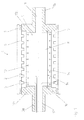
- roller 1 In the Fig. 1 the roller 1 according to the invention is shown. It has a circumferential jacket 2, which is mounted at each axial end by means of bearings 9 on a respective pin 3a, 3b.
- the bearing is designed so that the jacket 2 is movable radially to the axis 4 at least in the direction of a counter-pressure element, not shown. For this movement and the contact pressure on the counter-pressure element provide support elements 5, which are supported hydraulically on the axis 4.
- the axis is constructed in three layers in the embodiment.
- a top flange 6 and a bottom flange 7 are provided, which are connected to end pieces 13a, 13b, which in this embodiment form a unit with the pins 3a, 3b, for example, welded.
- both the material of the pin and the straps steel are steel.
- the main component 8 of the axle 4 consists of a castable or foamable composite material.
- the preferred castable composite is a concrete
- the preferred foamable composite is a metal foam.
- the pins are each provided with a hollow bore 11, which is also filled by the composite material.
- This has the advantage that the composite material can be easily introduced through the hollow bore of the pins in the space between the straps 6, 7 and the end pieces 13a, 13b in the production of the roller.
- lines 12 can be poured in, which serve the hydraulic pressure medium supply of the support elements 5. Elaborate axial longitudinal bores in the axis 4 of the Biegeeinstellwalze 1 can thus be avoided.
- the main component of the axle is prestressed by means of a tensioning element 14.
- a tensioning element 14 for this purpose, a threaded rod 15 with a radial distance in the concrete part, so the main component 8 of the axle 4 is poured with and loaded on the end pieces 13a, 13b via nuts 16 to train.
- the main component 8 is thereby pressurized so that it may possibly also absorb slight tensile stresses resulting from the loading of the roller 1 with the counterpressure element.
- FIG. 2 shows a cross section through the axis according to the invention 4. It shows that the support elements 5 consist of a piston member 17 with a support shoe 18 and a cylinder chamber 19 in the upper flange 6 or lower flange 7.
- the pressure chamber 20 is supplied via a supply line 22 with a pressure medium, wherein the supply line 22 is in communication with a cast-in main component 8 line 12.
- part of the pressure medium can be conveyed through a capillary bore 21 between the inner circumference of the jacket and the support shoe 18 in order to act as a lubricant there.
- the pressure medium supply can also take place via an outer line 23, which is attached from the outside to the appropriate axis.
- item number 24 indicates that reinforcements can also be poured into the concrete. Particularly advantageous is the possibility to pour a vibration damper 25 in the concrete or at least to install in a recess.
- the damped spring-mass system of the absorber is tuned to a resonant frequency of the roller or the axis in order to avoid or at least reduce vibrations occurring during operation.
Landscapes
- Physics & Mathematics (AREA)
- Fluid Mechanics (AREA)
- Engineering & Computer Science (AREA)
- General Engineering & Computer Science (AREA)
- Mechanical Engineering (AREA)
- Rolls And Other Rotary Bodies (AREA)
- Paper (AREA)
Applications Claiming Priority (1)
| Application Number | Priority Date | Filing Date | Title |
|---|---|---|---|
| DE200910000738 DE102009000738A1 (de) | 2009-02-10 | 2009-02-10 | Biegeeinstellwalze |
Publications (2)
| Publication Number | Publication Date |
|---|---|
| EP2216558A2 true EP2216558A2 (fr) | 2010-08-11 |
| EP2216558A3 EP2216558A3 (fr) | 2012-08-15 |
Family
ID=42173228
Family Applications (1)
| Application Number | Title | Priority Date | Filing Date |
|---|---|---|---|
| EP09177984A Withdrawn EP2216558A3 (fr) | 2009-02-10 | 2009-12-04 | Rouleau à réglage de la flexion |
Country Status (2)
| Country | Link |
|---|---|
| EP (1) | EP2216558A3 (fr) |
| DE (1) | DE102009000738A1 (fr) |
Cited By (1)
| Publication number | Priority date | Publication date | Assignee | Title |
|---|---|---|---|---|
| CN118385095A (zh) * | 2024-06-27 | 2024-07-26 | 晋江市豪欣隆纺织科技有限公司 | 一种涂布机 |
Family Cites Families (4)
| Publication number | Priority date | Publication date | Assignee | Title |
|---|---|---|---|---|
| DE29613795U1 (de) * | 1996-07-12 | 1996-12-05 | Inometa GmbH, 32052 Herford | Walze mit optimiertem Biegeverhalten |
| US5979305A (en) * | 1998-03-26 | 1999-11-09 | Appleton Papers, Inc. | Method and apparatus for controlling deflection of a roll |
| FI119446B (fi) | 2004-03-23 | 2008-11-14 | Metso Paper Inc | Paperi-/kartonkikoneen tai jälkikäsittelykoneen telan sisäpuolinen pitkänomainen rakenne |
| DE102004025116A1 (de) * | 2004-05-21 | 2005-12-08 | Voith Paper Patent Gmbh | Faserverbund Walzenbezug |
-
2009
- 2009-02-10 DE DE200910000738 patent/DE102009000738A1/de not_active Withdrawn
- 2009-12-04 EP EP09177984A patent/EP2216558A3/fr not_active Withdrawn
Cited By (1)
| Publication number | Priority date | Publication date | Assignee | Title |
|---|---|---|---|---|
| CN118385095A (zh) * | 2024-06-27 | 2024-07-26 | 晋江市豪欣隆纺织科技有限公司 | 一种涂布机 |
Also Published As
| Publication number | Publication date |
|---|---|
| EP2216558A3 (fr) | 2012-08-15 |
| DE102009000738A1 (de) | 2010-08-12 |
Similar Documents
| Publication | Publication Date | Title |
|---|---|---|
| DE69811502T2 (de) | Bezug für walze und verfahren zu deren herstellung | |
| DE19829829A1 (de) | Verbundwerkstoff-Teleskopteil und -ausleger | |
| EP1025996A1 (fr) | Cylindre porte-cliché | |
| DE2237949A1 (de) | Walze | |
| DE102008041268A1 (de) | Walze für Auftragseinrichtung und Verfahren zum Auswuchten einer Walze | |
| EP0621381A1 (fr) | Elément d'armature précontraint | |
| EP2216558A2 (fr) | Rouleau à réglage de la flexion | |
| DE602005003460T2 (de) | Länglicher, nicht drehbarer Innenaufbau einer Walze einer Papiermaschine/Kartonmaschine oder Finishingmaschine | |
| EP2100694B1 (fr) | Procédé de fabrication d'une machine d'usinage avec une partie en béton | |
| DE102005027173B4 (de) | Zug-Druckstrebe aus Faserverbundwerkstoff und Verwendung im Flug- und Fahrzeugbau | |
| EP2468408A2 (fr) | Gaine de rotor et jante pour meule, meule et procédé de fabrication de la meule | |
| EP3004457B1 (fr) | Cylindre et production d'un axe de cylindre | |
| DE60304893T2 (de) | Verstärkte rohrstrukturen | |
| DE102019100687B4 (de) | Keiltriebwerkzeug | |
| FI71971C (fi) | Foerfarande och anordning foer tillverkning av boejspaenningsunderkastade byggnadselement av trae. | |
| DE4400678A1 (de) | Presse zum Ziehen hohler Gegenstände aus Metallblech | |
| DE19940424A1 (de) | Walze | |
| DE102019100274A1 (de) | Schwingungsdämpfer und arrangement in einer faserbahnmaschine | |
| DE102016211176A1 (de) | Verfahren und Vorrichtung zur Herstellung von Betonbauteilen | |
| EP1956138B1 (fr) | Rouleau compresseur | |
| AT506514B1 (de) | Balkenkonstruktion für papier- und kartonherstellungsmaschinen so wie ein verfahren zu deren herstellung | |
| DE4016038C2 (fr) | ||
| EP1956137A2 (fr) | Rouleau compresseur | |
| DE102010029431A1 (de) | Mittengestützte Walze | |
| DE318214C (fr) |
Legal Events
| Date | Code | Title | Description |
|---|---|---|---|
| PUAI | Public reference made under article 153(3) epc to a published international application that has entered the european phase |
Free format text: ORIGINAL CODE: 0009012 |
|
| AK | Designated contracting states |
Kind code of ref document: A2 Designated state(s): AT BE BG CH CY CZ DE DK EE ES FI FR GB GR HR HU IE IS IT LI LT LU LV MC MK MT NL NO PL PT RO SE SI SK SM TR |
|
| AX | Request for extension of the european patent |
Extension state: AL BA RS |
|
| PUAL | Search report despatched |
Free format text: ORIGINAL CODE: 0009013 |
|
| AK | Designated contracting states |
Kind code of ref document: A3 Designated state(s): AT BE BG CH CY CZ DE DK EE ES FI FR GB GR HR HU IE IS IT LI LT LU LV MC MK MT NL NO PL PT RO SE SI SK SM TR |
|
| AX | Request for extension of the european patent |
Extension state: AL BA RS |
|
| RIC1 | Information provided on ipc code assigned before grant |
Ipc: D21G 1/02 20060101ALI20120710BHEP Ipc: F16C 13/02 20060101AFI20120710BHEP |
|
| STAA | Information on the status of an ep patent application or granted ep patent |
Free format text: STATUS: THE APPLICATION IS DEEMED TO BE WITHDRAWN |
|
| 18D | Application deemed to be withdrawn |
Effective date: 20130216 |