EP2468408A2 - Gaine de rotor et jante pour meule, meule et procédé de fabrication de la meule - Google Patents
Gaine de rotor et jante pour meule, meule et procédé de fabrication de la meule Download PDFInfo
- Publication number
- EP2468408A2 EP2468408A2 EP11010056A EP11010056A EP2468408A2 EP 2468408 A2 EP2468408 A2 EP 2468408A2 EP 11010056 A EP11010056 A EP 11010056A EP 11010056 A EP11010056 A EP 11010056A EP 2468408 A2 EP2468408 A2 EP 2468408A2
- Authority
- EP
- European Patent Office
- Prior art keywords
- rim
- reinforcement
- matrix
- rotor shell
- wedge
- Prior art date
- Legal status (The legal status is an assumption and is not a legal conclusion. Google has not performed a legal analysis and makes no representation as to the accuracy of the status listed.)
- Withdrawn
Links
Images



Classifications
-
- B—PERFORMING OPERATIONS; TRANSPORTING
- B02—CRUSHING, PULVERISING, OR DISINTEGRATING; PREPARATORY TREATMENT OF GRAIN FOR MILLING
- B02C—CRUSHING, PULVERISING, OR DISINTEGRATING IN GENERAL; MILLING GRAIN
- B02C15/00—Disintegrating by milling members in the form of rollers or balls co-operating with rings or discs
- B02C15/004—Shape or construction of rollers or balls
- B02C15/005—Rollers or balls of composite construction
-
- B—PERFORMING OPERATIONS; TRANSPORTING
- B02—CRUSHING, PULVERISING, OR DISINTEGRATING; PREPARATORY TREATMENT OF GRAIN FOR MILLING
- B02C—CRUSHING, PULVERISING, OR DISINTEGRATING IN GENERAL; MILLING GRAIN
- B02C15/00—Disintegrating by milling members in the form of rollers or balls co-operating with rings or discs
- B02C15/14—Edge runners, e.g. Chile mills
Definitions
- the invention relates to a rotor shell for attachment to a rim of a Koller ceremoniesrs, which is intended to work up ceramic materials, such as clay by lying on the bed of a mullion lying grind through the rolling therefrom Koller runner and / or are shredded.
- the invention relates to a rotor shell for releasably attaching to the rim of the Kollerniesrs, so that in use, mounted runner coat can be exchanged after exceeding an example predetermined degree of wear against a new rotor shell.
- Roller runners are driven wheel rollers of high weight, which roll on the outside of the rotor shell, which is also called rotor ring.
- the rotor shell is attached to the rim or the radially inner rotor body.
- the rotor shell has a substantially cylindrical, flat rolling surface.
- a Koller setupr usually rolls in a circular pug mill on the so-called runner bed, the Koller runners due to their high weight pressure and shear effects the ceramic material, which makes it shred.
- a rotor shell for particular releasable attachment to a rim of a Koller collaborationrs for crushing and / or scraping a ceramic material, such as clay provided, wherein the rotor shell is formed by a non-positive reinforcement matrix composite, consisting essentially of one of the Rim to be fastened, in particular rigid reinforcement, in particular a steel reinforcement, and a reinforcing at least partially surrounding, hydraulically bonded matrix, such as concrete, composed.
- the hydraulically bonded matrix is at least partially cast on at least part of the reinforcement so that outer surfaces of the reinforcement remain partially uncovered by the matrix.
- the rotor shell preferably consists exclusively of the reinforcement-matrix composite.
- the outside of the rotor shell, on which the roller runner is to roll, is formed exclusively of the material of the matrix, in particular concrete.
- the reinforcement-matrix composite is a steel-concrete composite, wherein the reinforcement is made of steel, is cast on the concrete and anchored in the solidified concrete frictionally.
- the production investment costs for providing ceramic at the production station of a mulling gang can be significantly reduced.
- the rotor shell according to the invention can be stored easily and space-saving.
- its weight is significantly lower than the weight of conventional steel cast rotor jackets.
- a force-locking connection between the reinforcement and the matrix results in the reinforcement-matrix composite, so that fastening forces acting on the reinforcement as well as prestressing forces which are to be transferred from the reinforcement into the matrix can be directly introduced and deduced are.
- the reinforcement is tensioned in the unassembled as well as the assembled state while the matrix is biased under pressure.
- the matrix is biased under pressure.
- the reinforcement is cast in contact with the matrix, in particular exclusively on an outer peripheral side facing away from the rim.
- the armor is at least partially exposed on one of the rim facing inner peripheral side of the matrix, so that support surfaces are formed for the reinforcement on which a fastening device for bracing the reinforcement and the rim can be used.
- the reinforcement is composed of several components to be mounted separately, in particular steel.
- the reinforcement can consist of peripheral parts and transverse parts. In this way, a high flexibility in the design of the reinforcement for differently sized Koller runners is given.
- the reinforcement has at least one parallel to the outer periphery of the rim extending, in particular closed clamping ring, preferably a plurality, preferably three, four or five, in particular parallel juxtaposed clamping rings.
- the clamping rings are in an axial, in particular constant distance arranged from each other.
- the clamping rings are used to build pressure biases in the at least partially cast around the clamping rings matrix by a tensioning rings already supplied Buchvorschreib is correspondingly reduced, being released when releasing the tension, the released forces in the firmly cast on the reinforcement matrix to build the compressive stress ,
- the matrix is seated radially outward on the reinforcement, with the inside of the reinforcement being free of matrix to provide support surfaces towards the rim, so that the assembly forces are communicated to the reinforcement-matrix composite solely by the reinforcement when attaching the reinforcement to the rim ,
- the reinforcement can be embedded in the matrix at least partially, preferably on the side facing away from the rim, for a force-transmitting positive connection.
- the at least one clamping ring has a closed, in particular circular ring structure whose cross-section is in particular rectangular. In this way, a uniform compressive bias is introduced into the matrix and a mounting assembly force input into the rim along a 360 ° circumference, with the tension ring being sufficiently torsionally rigid.
- the reinforcement has several, in particular more than two, three, four or five, preferably six, transverse struts, in particular for receiving and / or positioning and / or aligning the at least one clamping ring along the rim.
- the transverse struts which in particular extend axially, are arranged substantially stationary in an angular circumferential section relative to one another on the outer circumference of the rim, wherein the angular circumferential distance is in particular constant. In this way, a uniform force input of the reinforcement in the rim and of the cross struts in the at least one clamping ring is ensured.
- the plurality of transverse struts for the at least one clamping ring each have a receiving recess which is formed in particular on an outer side facing away from the rim of the respective transverse strut and / or defines an axial distance between two adjacent clamping rings.
- a positionally accurate alignment and Arrangement of the clamping rings also specified in particular during the casting of the matrix to the reinforcement and the solidification of the matrix, wherein matrix cavities can be largely prevented.
- the plurality of recesses are arranged in a particular constant axial distance from each other.
- the transverse strut is formed by a plurality of spaced apart in an axial distance spacer blocks, in particular the receiving recess is determined by the axial distance, and formed by a crossbar for receiving the plurality of spacer blocks.
- the at least two spacer blocks are pushed onto the crossbar, in that each spacer block has a through hole into which the crossbar is inserted.
- the transverse struts each have a support surface free of the matrix and facing the rim, which is in particular substantially curved according to a curvature, in particular a circumferential radius, of the rim and / or relative to the axial direction, which is parallel to the roll axis of the roller runner , wedge-shaped conical, in particular, a radial thickness of the transverse struts in particular decreases uniformly from a maximum substantially in the axial center of the rotor shell towards the respective axial end edge. In this way, a positive exposure of the reinforcement to the cylindrical rim or a cylindrical intermediate part between the rim and the reinforcement can be ensured.
- each transverse strut facing away from the rim and an outer side of the at least one clamping ring facing away from the rim lie substantially on a common cylindrical circumferential plane which is concentric to a rotational axis of the rotor mantle.
- the outside of the at least one clamping ring can also be slightly offset radially inwards relative to the outside of the transverse strut be. Preferably, these outsides are completely covered by the matrix.
- each transverse strut has a crossbar on which the at least one clamping ring loosely applied and then attached, in particular welded, can be.
- each transverse strut can be made of one piece, in particular of a piece of metal. It is clear that some cross struts of the reinforcement can be formed by a plurality of components, while other cross struts are integral.
- means are provided for attaching the reinforcement-matrix composite, in particular the reinforcement, to the rim of the roller bearing rotor.
- the fastening device may be movably mountable between the reinforcement, preferably the transverse struts and the rim, that the reinforcement is at least partially, in particular the at least one clamping ring, biased to train and / or that the molded matrix jacket is biased to pressure.
- the compressive prestress in the matrix is achieved by prestressing, ie widening, the reinforcement already applied to the rim or to an assembly aid prior to casting, while subsequently the matrix jacket is cast onto the reinforcement and solidifies. After the solid state of the matrix has been established, a portion of the tension prestress of the reinforcement is built up, thereby contracting the reinforcement and simultaneously biasing the matrix, firmly bonded to the reinforcement, from the reinforcement to pressure.
- the attachment means is formed by a device for radially spreading the reinforcement against the rim and / or for radially contracting or shrinking the reinforcement against the fixed matrix.
- the spreading and / or shrinking device may be formed by a wedge structure, which is in particular axially on and pushed out between the reinforcement and the rim, so that the reinforcement is widened and thus stretched to train and / or the particular prestressed on train reinforcement contracts radially so that the matrix is compressible to pressure.
- the shrinking device has means for storing contraction forces that are used to communicate to the matrix to create a compressive bias within the matrix.
- the spreading and / or shrinking device also includes a device for storing, in particular, holding tensile prestresses. Only at the desired time, in particular when the matrix has solidified, are the tensile stresses released in order to generate the compressive prestress in the matrix.
- a wedge structure is provided for each transverse strut, wherein in particular the wedge structure is structurally identical for each cross strut.
- the wedge structure has two wedge elements located axially opposite each other, which are formed substantially identical in shape and in particular are mounted symmetrically to a radial center axis plane of the rotor shell.
- the two wedge elements each have one or two opposite the axial direction inclined Verspannnchin, which are facing the reinforcement and / or rim. Both inclined clamping sides are opposite each other. The one tensioning side or the two tensioning sides are engaged with a complementary complementary side of the reinforcement and / or rim in such a way that the reinforcement is widened and thus tensioned or can contract radially in order to bias the matrix to pressure.
- the two wedge elements have two opposite, with respect to the axial direction of the rotor shell inclined clamping sides, wherein the inclination angle of the respective Verspannseite coincides with the inclination angle of the thus brought into engagement opposite side of the reinforcement and a corresponding rim portion.
- the spreading and / or shrinking device is realized in such a way that the two wedge elements can be moved back and forth substantially in the axial direction, so that the wedge elements engage with the reinforcement and the rim with increasing or decreasing radial thickness.
- the wedge structure has a mechanism for in particular continuous reciprocation of the two wedge elements.
- the mechanism may be formed by a threaded rod, at the two end regions in each case a wedge element is in particular threadedly engaged to build Montagezug- or -druck mechanism between the wedge elements.
- the invention relates to a rim or a transport rim as a transport aid of a particular runner jacket according to the invention for a Kollerformatr for grinding and / or scraping a ceramic material, such as clay, wherein on the rim an especially mentioned above, according to the invention runner jacket to form the Kollerconsrs can be pulled.
- a plurality, in particular more than two, three, four or five, preferably six, recesses for at least partially receiving the device for fastening the rotor shell, in particular the reinforcement matrix composite, are molded onto the rim on the outer and peripheral sides of the rim ,
- the recesses can be used for positioning, aligning and / or guiding a wedge structure or fastening device.
- the depressions have, in particular at an edge region, a base surface which is inclined relative to the axial direction and curved in particular in the circumferential direction.
- a center axis distance of the bottom surface from an axis of rotation of the rim increases steadily in the direction of a radial central axis plane of the rotor shell.
- the inclination of the bottom surface of the respective recess corresponds to an inclination of the rim facing wedge surface of the wedge member of the wedge structure for spreading or radial contraction of the reinforcement.
- the inclined bottom surface edge portion of the recess is formed to partially receive a wedge member of the wedge structure.
- axially opposite edge regions with inclined bottom surface are connected by a radially outwardly open, in particular part-cylindrical groove, which can completely accommodate the threaded rod of the mechanism for reciprocating the two wedge elements.
- the rim is at least partially made by a heavy metal, in particular lead.
- the invention relates to a Koller simplifiedr for unrolling on a quenching bed of a muller for processing, in particular grinding and crushing, ceramic masses, wherein the Kollerformatr has a rim according to the invention and / or arranged around a rotor skirt according to the invention.
- the invention relates to a method for producing a rotor shell according to the invention for a Koller runner, in which a reinforcement is loosely placed on the outer periphery of a particular rim according to the invention or a particular inventive rim simulating transport aid.
- a reinforcement is loosely placed on the outer periphery of a particular rim according to the invention or a particular inventive rim simulating transport aid.
- the runner jacket acts as a spare part
- transport aids are used for the runner coats.
- the rim or the transport aid and an additional outer formwork for forming a closed casting space are arranged around the reinforcement.
- a hydraulically bonded matrix such as concrete, is filled in the casting space. Once the matrix has solidified, the outer formwork can be disassembled without removing the rim or the transport aid. Only in the case of use, the transport aid can be removed to raise the runner jacket produced according to the inventive method on the rim of the Koller confusers.
- the reinforcement is not covered or encapsulated with matrix on the side facing the rim or transport aid.
- the reinforcement prior to filling the casting space with the matrix, the reinforcement is widened radially, in particular under the use of the spreading device, so that the reinforcement, in particular the at least one tensioning ring, is pre-tensioned and secured to the rim or the transport aid. Subsequently, the tensile-stressed reinforcement is encapsulated with matrix.
- the tensile prestress of the reinforcement is at least partially released, thereby establishing a compressive prestress in the matrix.
- the reinforcement provides a means for storing forces to generate compressive stresses in the matrix. The stored forces caused the matrix to contract. As the reinforcement contracts, the matrix cast on the reinforcement is dragged along and thus contracted, creating internal compressive stresses in the matrix.
- At least a portion of the compressive prestress in the matrix is repealed by spreading the reinforcement and wedging the reinforcement in the rim. It should be understood, however, that preferably both a residual tensile bias in the reinforcement and a residual compressive bias should remain in the matrix.
- a pair of Koller runner is generally provided with the reference numeral 1 and 3, wherein the Koller runner 1 occupies an outer web 2 of a puffer bed 17 of a pug mill 6, while the Koller runner 3 describes an inner web 4.
- Both Koller runners 1 and 3 are each coupled via a cantilever arm 5, 7 with a drive shaft 11 which rotates the Koller runners 1, 3 on their respective circular path.
- a drive shaft of the drive shaft is vertically aligned, wherein the extension arms 5, 7 are horizontal perpendicular thereto.
- the Koller runners 1, 3 are at the respective center piece 5, 7 via so-called drag cranks 13, 15 rotatably mounted about a rotational axis D of Koller frustrationrs 1, 3, wherein the axis of rotation D to a parallel thereto and arranged in a pivoting distance, horizontal bearing axis, the stationary with respect to the respective extension arm 5, 7 is pivotable.
- the cylindrical Koller runners 1, 3 roll on the so-called kneader table 17, which is formed by a grid structure on which the ceramic material to be processed, such as clay, falls to be crushed and crushed under the influence of the weight of the Koller runners 1, 3.
- the squeegee 17 is supported by a frame 21 of the muller 6, which stands on four pillars 23.
- the Koller runner 1, 3 consists essentially of a rotor shell 25 which is arranged concentrically to the rotational axis D of Koller frustrationrs 1, 3, and a rim 27 which is surrounded by the rotor shell 25 radially outward.
- the rotor shell 25 is detachably mounted on the rim 27 of the Koller runner 1, 3 according to the invention to be replaced when exceeding a certain degree of wear of the rotor shell 25 against an unused rotor shell 25.
- FIG. 2 an inventive Koller runner 1, 3 is shown in detail.
- a vollmassiger, solid rim body 28 of the rim 27, which serves to provide the weight, is formed of a material with high lead content and comprises a concentric with the axis of rotation D formed passage for receiving an inner bearing sleeve 29 which receives a pivot bearing to that of the Koller runner. 1 , 3 can rotate.
- the rim body 28 may have a plurality of recesses 30 as a carrying and gripping aid and / or for adjusting the weight mass.
- each recesses 31 is introduced, which consists of two opposing, identically shaped edge portions 33, 35 and the two edge portions 33, 35 connecting channel 37.
- the depression 31 is designed to be symmetrical about the radial center axis M.
- the recesses 31 serve to at least partially accommodate a means for securing the rotor shell 25 to the rim 27, the fastening means also serving to impart a compressive bias to one part of the rotor shell 25 and a tension to another part of the rotor shell 25.
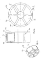
- FIGS. 3a to 3c a so-called transport rim or a transport aid for merely transporting a rotor shell 25 is shown.
- the transport rim is generally designated by the reference numeral 27a.
- the transport rim 27a differs from the rim 27 according to FIGS FIGS. 2a to 2c in that it has a much lower weight, because it is not used for a Koller runner, but only to transport the rotor shell, which is intended to be mounted on a rim 27 of Koller devisrs 1, 3.
- the outer peripheral side 32a is structured the same as the outer peripheral side 32 of the rim 27 according to FIGS FIGS.
- the transport rim 27a has on its outer peripheral side 32a six recesses 31a which define edge portions 33a, 35a at the axial end edge of the transport rim 27a and a groove 37a connecting the edge portions 33a, 35a.
- the depressions 31a serve to partially receive the fastening device in order to communicate the desired pressure and / or tensile prestress to the rotor shell 25 even during its transport.
- the transport rim 27a is formed of a lightweight material, such as aluminum, wood or plastic, wherein the transport rim body 28a is formed by a plurality of large-flowered spaces.
- the transport rim 27a also has an inner passage concentric with the axis of rotation D in order to be storable on a transport spindle.
- the rotor shell 25 is realized from a reinforcement-matrix composite, for example from a reinforced concrete composite.
- the matrix forms a pure outer concrete shell 41, wherein the reinforcement is realized by a reinforcement 43.
- the thickness t of the outer concrete shell 41 represents the maximum amount of wear that can be abraded until the rotor shell 25 has to be replaced with a new one.
- the concrete shell 41 is cast directly to the steel reinforcement 43 only on the rim 27 facing away from the outside of the reinforcement 43, wherein the rim 27 facing the inside of the reinforcement 43 is free of concrete material.
- the radial sides of the reinforcement 43 are embedded in concrete material, so that a frictional bond between the concrete and the steel reinforcement 43 is created.
- An axial peripheral end edge of the concrete jacket 41 is rounded or chamfered.
- the concrete shell 41 continuously forms along its circumference substantially a U-shape with a stronger ring base, which extends over the entire width of the Koller scholarrs 1, 3.
- the U-shaped concrete shell 41 also has two narrow, parallel ring legs, whose thickness is less, preferably less than half the thickness of the U-shaped base of the concrete shell 41.
- the ring legs extend radially at most about an edge width of the reinforcement 43 at its axial ends.
- the concrete shell 41 is biased due to manufacturing measures, which will be explained later, pressure. In this way, the rotor shell 25 against the operating loads and load peaks when rolling on the rotor bed 17 is much more resistant to wear.
- the steel-concrete rotor shell 25 of the reinforcement 43 made of steel, on the radially outer side of the rotor shell 41 is firmly attached.
- the reinforcement 43 consists of six transverse struts 47, which extend substantially over the entire width b of the Koller scholarrs 1, 3.
- the width of the reinforcement 43, in particular of the transverse strut 47 is smaller than the axial width b of the Koller runners 1, 3 exactly at the axial width of the annular limbs of the concrete jacket 41.
- the reinforcement 43 has three clamping rings 49, which are fastened to the transverse struts 47.
- the clamping rings 49 and the cross member 47 are made of one piece of steel.
- the clamping rings 49 are closed in the circumferential direction U and extend annularly parallel to the circumferential outer side 32 of the rim 27, wherein a cylindrical space between the inside of the clamping rings 49 and the outer peripheral side 32 of the rim 27 is formed for the fastening device.
- the clamping rings 49 have a rectangular shape in cross section.
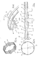
- FIGS. 4a to c a particular embodiment of the reinforcement 43 is shown, which differs from the execution of the reinforcement 43 according to the FIGS. 2a to c characterized in that separate clamping rings 49 are welded to the cross member 47.
- the transverse strut 47 also consists of a plurality of separate components to be assembled, namely a transverse rod 51, to which the clamping rings 49 are welded, and four spacer blocks, which are also welded to the crossbar 51, wherein benachbarte distance blocks 53-55, 55-57, 57-59 each define a receiving recess 61, in each of which a clamping ring 49 is inserted in the radial direction R and completely absorbed.
- a radial outside is aligned At least, the radial outer side of the clamping ring 49 is not located in the radial direction R above the radial outer side of the spacer blocks 53 to 59 of the clamping rings 49 with the radial outer sides of the spacer blocks.
- each spacer block 53 to 59 is curved in the circumferential direction U, wherein the radius of curvature corresponds to the center axis distance to the rotation axis D.
- the radial inner surface 65 of each spacer block 53 to 59 is inclined with respect to an axial direction A, so that the radial thickness s of the transverse strut 47 steadily increases in the direction of a central axis M to form a two-sided wedge structure.
- Each spacer block 53 to 59 has a through hole 67 through which the cross bar 51 is inserted for radial reception of the spacer blocks 53 to 59.
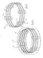
- FIGS. 5a and b is indicated as the concrete shell 41
- the in FIG. 5b dashed lines is indicated, is molded radially on the outside of the reinforcement 43.
- the concrete casing 41 is cast onto the reinforcement 43 such that one of the rim 27 facing the inside of the reinforcement 43 remains free of concrete material.
- the concrete shell 41 can be loaded on train or on pressure. It is clear that to increase the wear resistance of the concrete shell 41 is to stress on pressure.
- a first radial outer shell 71 for limiting a casting space 73 is arranged radially outwardly around the rim 27, 27a.
- the rim 27, 27a may have a radially inner shoulder 75 which is shaped complementary to a projection 77 of the outer shell 71.
- a fastener 81 is mounted between the outer peripheral side of the rim 27, 27a and the inner peripheral side of the armor 43, so that the armor 43 is biased to tension.
- the fastening device 81 may also be referred to as a spreading and / or shrinking device, because it serves to either radially spread the armor 43 or to contract radially, depending on how the fastening device 81 relative to the reinforcement 43 and the rim 27, 27a is arranged.
- the fastening device 81 consists of a wedge structure, which is formed by two substantially identically shaped wedge elements 83, 85, which are connected to one another via a threaded rod 87.
- the threaded rod 87 serves as a mechanism for pulling the wedge members 83, 85 together or removing the wedge members 83, 85 from each other.
- Each wedge element 83, 85 comprises a wedge outer surface 98 facing the reinforcement 43 and a wedge inner surface 91 facing the rim 27, 27a.
- the wedge outer and inner surfaces 89, 91 are inclined to the axial direction A at a small, acute angle, wherein the inclination angle of the wedge outer surface 89 corresponds to the inclination angle of the inner radial surface 65 of the transverse strut 47.
- the inclination angle of the wedge inner surface 91 corresponds to the inclination angle of a bottom surface 39 of a peripheral portion 33, 35 of the recess 31.
- the angle of inclination of the wedge inner surface 91 is greater than the inclination angle of the wedge outer surface 89.
- the wedge members 83, 85 are engaged by the threaded rod 87, the rotation of which causes the wedge members 83, 85 to move toward or away from each other.
- the outer shell 71 and the lid 93 axially aligned openings 95, 97 project through the wedge elements 85 in the assembled state of the outer shell 71 and the lid 93, wherein the casting space 73 is directly closed.
- the concrete material is injected through an opening, not shown, in the outer shell 71 to partially encase the prestressed on train reinforcement 43 with concrete.
- the outer shell 71 and the lid 93 can be dismantled, as well as the rim 27, 27 a.
- the reinforcement 43 contracts due to the stored Switzerlandvorschreib, whereby the rigid concrete shell 41, which is non-positively molded to the reinforcement 43, is biased to pressure.
- the runner jacket 25 can be mounted on a rim 27 of a Kollerierirs 1, 3 by only a portion of the degraded tensile stresses are applied by approaching the wedge members 83, 85, whereby clamping forces are caused with the rim 27 but a part of the compression bias in the Coat is preserved.
Landscapes
- Engineering & Computer Science (AREA)
- Food Science & Technology (AREA)
- Hydraulic Turbines (AREA)
Applications Claiming Priority (1)
| Application Number | Priority Date | Filing Date | Title |
|---|---|---|---|
| DE201010056044 DE102010056044A1 (de) | 2010-12-23 | 2010-12-23 | Läufermantel und Felge für einen Kollerläufer, Kollerläufer sowie Verfahren zum Herstellen des Kollerläufers |
Publications (1)
| Publication Number | Publication Date |
|---|---|
| EP2468408A2 true EP2468408A2 (fr) | 2012-06-27 |
Family
ID=45470182
Family Applications (1)
| Application Number | Title | Priority Date | Filing Date |
|---|---|---|---|
| EP11010056A Withdrawn EP2468408A2 (fr) | 2010-12-23 | 2011-12-21 | Gaine de rotor et jante pour meule, meule et procédé de fabrication de la meule |
Country Status (2)
| Country | Link |
|---|---|
| EP (1) | EP2468408A2 (fr) |
| DE (1) | DE102010056044A1 (fr) |
Cited By (4)
| Publication number | Priority date | Publication date | Assignee | Title |
|---|---|---|---|---|
| EP3028766A1 (fr) * | 2014-12-05 | 2016-06-08 | Alite GmbH | Broyeur pour four à calciner |
| CN111530612A (zh) * | 2020-06-06 | 2020-08-14 | 青岛迪凯自动化设备有限公司 | 新型碾轮 |
| US11224881B2 (en) | 2015-03-05 | 2022-01-18 | Mitsubishi Power, Ltd. | Grinding roller and mill |
| CN118237128A (zh) * | 2024-04-22 | 2024-06-25 | 青岛龙迪碳材料科技有限公司 | 一种石墨烯加工装置及方法 |
Families Citing this family (1)
| Publication number | Priority date | Publication date | Assignee | Title |
|---|---|---|---|---|
| CN111013999B (zh) * | 2019-12-19 | 2023-05-09 | 江西璞晶新材料股份有限公司 | 一种筛分细粉物料的电动锥筒碾式细粉物料筛分设备 |
Family Cites Families (2)
| Publication number | Priority date | Publication date | Assignee | Title |
|---|---|---|---|---|
| DE3815218A1 (de) * | 1988-05-04 | 1989-11-16 | Loesche Gmbh | Luftstrom-mahlanlage |
| DE9308643U1 (de) * | 1993-06-09 | 1993-08-12 | Händle GmbH & Co. KG., 75417 Mühlacker | Kollergang |
-
2010
- 2010-12-23 DE DE201010056044 patent/DE102010056044A1/de not_active Ceased
-
2011
- 2011-12-21 EP EP11010056A patent/EP2468408A2/fr not_active Withdrawn
Non-Patent Citations (1)
| Title |
|---|
| None |
Cited By (5)
| Publication number | Priority date | Publication date | Assignee | Title |
|---|---|---|---|---|
| EP3028766A1 (fr) * | 2014-12-05 | 2016-06-08 | Alite GmbH | Broyeur pour four à calciner |
| US11224881B2 (en) | 2015-03-05 | 2022-01-18 | Mitsubishi Power, Ltd. | Grinding roller and mill |
| CN111530612A (zh) * | 2020-06-06 | 2020-08-14 | 青岛迪凯自动化设备有限公司 | 新型碾轮 |
| CN111530612B (zh) * | 2020-06-06 | 2025-01-03 | 青岛迪凯自动化设备有限公司 | 碾轮 |
| CN118237128A (zh) * | 2024-04-22 | 2024-06-25 | 青岛龙迪碳材料科技有限公司 | 一种石墨烯加工装置及方法 |
Also Published As
| Publication number | Publication date |
|---|---|
| DE102010056044A1 (de) | 2012-06-28 |
Similar Documents
| Publication | Publication Date | Title |
|---|---|---|
| EP3821083B1 (fr) | Fondation d'une eoliènne | |
| EP3931399B1 (fr) | Fondation pour une éolienne | |
| WO2017045907A2 (fr) | Tour pour éolienne constituée d'éléments préfabriqués en béton en forme de segment annulaire | |
| EP2723544A2 (fr) | Production d'une tour | |
| EP2468408A2 (fr) | Gaine de rotor et jante pour meule, meule et procédé de fabrication de la meule | |
| WO2014037421A1 (fr) | Tour d'éolienne et procédé de construction | |
| DE202015100932U1 (de) | Vorrichtung zum Sichern, insbesondere Sanieren, eines Fundaments bei Windenergieanlagen, sowie Fundament | |
| EP4339398A1 (fr) | Segment de transition d'une tour d'éolienne | |
| DE3638259A1 (de) | Verfahren zur herstellung der wandauskleidung bei in schildbauweise hergestellten tunneln sowie schalung zur durchfuehrung des verfahrens | |
| CH644432A5 (de) | Ausbaurahmen, insbesondere fuer stollen und tunnel. | |
| DE102012110342B4 (de) | Rotorkörper für eine Zerkleinerungsvorrichtung, insbesondere einen Trommelhacker für die Zerkleinerung von Holz oder dergleichen | |
| WO2009015816A1 (fr) | Procédé de fabrication d'un élément de paroi | |
| DE102019116519A1 (de) | Schalungsvorrichtung und Verfahren zur gleichzeitigen Herstellung mehrerer konzentrisch ineinanderpassender Betonfertigteile unterschiedlicher Größe | |
| EP3475041B1 (fr) | Procédé et dispositif pour la fabrication de pièces en béton | |
| DE60117751T2 (de) | Verfahren zum Druckgiessen eines Brennkraftmaschinenblocks aus einer mit einer Eisenlegierung verstärkten Aluminiumlegierung und nach diesem Verfahren gegossener Brennkraftmaschinenblock | |
| DE4337791A1 (de) | Verbaurahmen | |
| DE102005036705A1 (de) | Verfahren zur Herstellung eines Hohlkörpers aus Beton sowie Hohlkörper und Schalung für die Herstellung eines Hohlkörpers | |
| AT386445B (de) | Schalplatte mit einer schalhaut | |
| DE857385C (de) | Walze mit hammelklauenfoermigen Ansaetzen | |
| DE594107C (de) | Verfahren zur Herstellung von Schleifersteinen | |
| DE4113572A1 (de) | Schleifscheibe und verfahren zu ihrer herstellung | |
| DE4334421C2 (de) | Einrichtung zum Ankuppeln und Spannen von Sägeblättern in einem Sägeblatttragrahmen einer Maschine zum Sägen von harten Steinmaterialien | |
| DE102025118584A1 (de) | Schalkörper und Verfahren zur Herstellung einer Bohrschablone für eine Bohrpfahlwand | |
| DE202012008759U1 (de) | Grundkern zur Fertigung von Schachtunterteilen | |
| DD223751A1 (de) | Gruendung fuer arbeitsmaschinen und ausruestungen |
Legal Events
| Date | Code | Title | Description |
|---|---|---|---|
| AK | Designated contracting states |
Kind code of ref document: A2 Designated state(s): AL AT BE BG CH CY CZ DE DK EE ES FI FR GB GR HR HU IE IS IT LI LT LU LV MC MK MT NL NO PL PT RO RS SE SI SK SM TR |
|
| AX | Request for extension of the european patent |
Extension state: BA ME |
|
| PUAI | Public reference made under article 153(3) epc to a published international application that has entered the european phase |
Free format text: ORIGINAL CODE: 0009012 |
|
| STAA | Information on the status of an ep patent application or granted ep patent |
Free format text: STATUS: THE APPLICATION IS DEEMED TO BE WITHDRAWN |
|
| 18D | Application deemed to be withdrawn |
Effective date: 20140701 |