EP2217873B1 - Kühlvorrichtung - Google Patents
Kühlvorrichtung Download PDFInfo
- Publication number
- EP2217873B1 EP2217873B1 EP08843923A EP08843923A EP2217873B1 EP 2217873 B1 EP2217873 B1 EP 2217873B1 EP 08843923 A EP08843923 A EP 08843923A EP 08843923 A EP08843923 A EP 08843923A EP 2217873 B1 EP2217873 B1 EP 2217873B1
- Authority
- EP
- European Patent Office
- Prior art keywords
- door
- actuator
- cooling device
- switch
- supplementary
- Prior art date
- Legal status (The legal status is an assumption and is not a legal conclusion. Google has not performed a legal analysis and makes no representation as to the accuracy of the status listed.)
- Active
Links
Images
Classifications
-
- F—MECHANICAL ENGINEERING; LIGHTING; HEATING; WEAPONS; BLASTING
- F25—REFRIGERATION OR COOLING; COMBINED HEATING AND REFRIGERATION SYSTEMS; HEAT PUMP SYSTEMS; MANUFACTURE OR STORAGE OF ICE; LIQUEFACTION SOLIDIFICATION OF GASES
- F25D—REFRIGERATORS; COLD ROOMS; ICE-BOXES; COOLING OR FREEZING APPARATUS NOT OTHERWISE PROVIDED FOR
- F25D23/00—General constructional features
- F25D23/02—Doors; Covers
- F25D23/025—Secondary closures
-
- F—MECHANICAL ENGINEERING; LIGHTING; HEATING; WEAPONS; BLASTING
- F25—REFRIGERATION OR COOLING; COMBINED HEATING AND REFRIGERATION SYSTEMS; HEAT PUMP SYSTEMS; MANUFACTURE OR STORAGE OF ICE; LIQUEFACTION SOLIDIFICATION OF GASES
- F25D—REFRIGERATORS; COLD ROOMS; ICE-BOXES; COOLING OR FREEZING APPARATUS NOT OTHERWISE PROVIDED FOR
- F25D27/00—Lighting arrangements
Definitions
- the present invention relates to a cooling device that comprises a supplementary door situated on the cooling device and/or the freezer door.
- a door is used for the access of the user to the objects loaded in cooling devices.
- the interior of the cooling device cooler than the outside, begins to get warmer when the cooling device door is opened and the operation period of the compressor is affected depending on the frequency of opening, closing the cooling device door and the duration of being left open.
- the cooling device door is opened and the bottle is taken out, causing the temperature of the entire cooling device interior to increase unnecessarily, and the operation period of the compressor and respectively the energy consumption of the cooling device increases.
- supplementary doors are known in the technique, allowing access of the user inside the cooling device without requiring opening the door of the cooling device.
- a means of illumination is necessary for viewing the interior of the body after the user opens the supplementary door. Therefore, a lamp is provided inside the body that changes to the active mode for illuminating the interior of the cooling device when the supplementary door is opened and a switch that shifts the lamp to the active mode.
- either a second lamp is used in addition to the lamp in the body for illuminating the space the supplementary door opens to or a switch in addition to the existing switch or a sensor is used for detecting the movement of the supplementary door.
- a second lamp or switch group results in the increase of the controls and the cable group wired to the second switch and the lamp. This creates a disadvantage for the producer in both labor and production costs.
- US 5966963 discloses a cooling device according to the preamble of claim 1.
- the aim of the present invention is the realization of a cooling device comprising a lamp that is shifted to the active mode by using a single switch upon opening of both the door and the supplementary door.
- the cooling device realized in order to attain the aim of the present invention, explicated in the first claim and the respective claims thereof, comprises a lamp for illuminating the cooling device interior volume, a switch that shifts the lamp to the active or passive mode and an actuator that triggers the switch by changing position and maintains the lamp to illuminate the cooling device interior volume when either the door or the supplementary door is opened.
- the switch that is triggered by the movement of the door is enabled to be also triggered by the movement of the supplementary door with the help of the actuator.
- the actuator triggers the switch by making a movement with the door when the door is opened and when the supplementary door opens by making a movement relative to the door.
- the lamp is turned on when either of the doors open (active mode). When both of the doors are closed, the lamp is turned off (passive mode).
- the actuator is disposed on the door and moves together with the door.
- the switch is triggered upon opening of the door. Accordingly, the lamp is turned on when the door opens.
- the actuator extends between the switch and the supplementary door and when all the doors are closed, exerts a pressure by both ends on the both the supplementary door and the switch.
- the switch is actuated and the lamp is turned on.
- the lamp is turned on because of the movement of both the door and the supplementary door triggering the switch.
- the cooling device comprises a protrusion disposed on the supplementary door, and when closed, one end of the actuator contacts thereto.
- the end of the actuator is in contact with the supplementary door when closed.
- the cooling device comprises preferably a spiral shaped spring that moves the actuator away from the switch when the supplementary door is opened.
- the cooling device comprises a pin whereon the actuator is disposed, forming the rotational axis of the actuator and a spring wrapped on the pin, the free ends thereof bearing on the actuator.
- the actuator is the same shape as the surface of the door facing inside of the body.
- the actuator bears against the door when the supplementary door is opened, and being of the same shape as the door, does not occupy space and an esthetic appearance is provided as well.
- the interior of the body can be illuminated by only using the existing lamp and switch upon opening of either the door or the supplementary door and without using an additional switch, lamp, sensor or cable group.
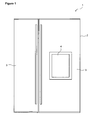
- Figure 1 - is the front view of a cooling device.
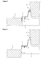
- Figure 2 - is the top cross-sectional view of the cooling device when the supplementary door is closed in an embodiment of the present invention.
- Figure 3 - is the top cross-sectional view of the cooling device when the supplementary door is open in an embodiment of the present invention.
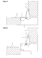
- Figure 4 - is the top cross-sectional view of the cooling device when the supplementary door is closed in an alternative embodiment of the present invention.
- Figure 5 - is the top cross-sectional view of the cooling device when the supplementary door is open in an alternative embodiment of the present invention.
- the cooling device (1) of the present invention comprises a body (2), a door (3) providing access of the user inside the body (2), an opening arranged on the door (3) that allows the user to access inside the body (2) without opening the door (3), a supplementary door (4) that covers the opening, openable when desired thereby allowing access of the user inside the body (2), a lamp that illuminates the interior of the body (2) and a switch (6) that shifts the lamp to the passive mode when pressure is exerted thereon and when the pressure thereon is released shifts the lamp to the active mode for illuminating the interior of the body (2) ( Figure 1 ).
- the cooling device (1) furthermore comprises an actuator (7) that changes position, actuating the switch (6) and maintaining the lamp to become active when either the closed door (3) or the supplementary door (4) is opened.
- the lamp inside the body (2) shifts to the active mode when the switch (6) is triggered by the actuator (7) that moves together with the door (3) as the door (3) opens, and moving relative to the door (3) as the supplementary door (4) opens.
- the actuator (7) makes a movement relative to the door (3) and independent from the door (3).
- the switch (6) is triggered and the lamp is turned on.
- the lamp in the body (2) is enabled to illuminate the interior of the body (2) both when the door (3) is opened and also when the supplementary door (4) is opened without requiring the use of a second lamp or a second switch.
- the switch (6) is disposed on the side wall of the body (2).
- the switch (6) and the lamp are electrically connected to each other with cables and the switch (6) controls whether or not electric current is flowing through the cables depending on its position.
- the switch (6) maintains the lamp to remain in the passive mode, not allowing electric current to flow from the cables when the door (3) and the supplementary door (4) are closed.
- the switch (6) allows electric current to flow from the cables and thus the lamp shifts to the active mode illuminating the volume containing thereof.
- the actuator (7) disposed on the door (3) extends between the switch (6) and the supplementary door (4) when the doors (3 and 4) are closed.
- the switch (6) is triggered and the lamp is shifted to the active or passive mode depending on whether the supplementary door (4) is open or closed.
- the switch (6) When the doors (3 and 4) are closed, one end of the actuator (7) bears on the switch (6) and one end bears on the supplementary door (4).
- the switch (6) remains in the closed position by means of the actuator (7) applying pressure thereon and maintains the lamp to stay in the passive mode. Since the actuator (7) is disposed on the door (3), it moves together with the door (3). This maintains the switch (6) to change to the open position every time the door (3) is opened thereby providing the lamp to illuminate the interior of the body (2), and when the door (3) is closed, the switch (6) is also turned off enabling the lamp to shift to the passive mode.
- the actuator (7) When the supplementary door (4) is opened while the door (3) is closed, and the force exerted on the end of the actuator (7) is released, the actuator (7) no longer applies pressure on the switch (6) and the switch (6) changes to the open position. As a result, the lamp shifts to the active mode and illuminates the interior of the body (2).
- the cooling device (1) comprises a protrusion (8) situated on one side of the supplementary door (4) that pushes the actuator (7) by being in constant contact with the actuator (7) when the supplementary door (4) is closed thereby enabling the other end thereof to be in contact with the switch (6) when the doors (3 and 4) are closed.
- the cooling device (1) comprises a spring (9) that maintains the actuator (7) to move such that contact with the switch (6) is lost when the force applied on the actuator (7) by the supplementary door (4) is released (when the supplementary door (4) is opened).
- the spring (9) activates the actuator (7) to move away from the switch (6) due to the energy stored thereon when the supplementary door (4) is opened.
- the spring (9) is spiral shaped and one end is secured to the actuator (7) and the other end to the door (3).
- the actuator (7) moves linearly by the pulling of the spring (9) that is initially tight and the pressure applied on the switch (6) by the actuator (7) is released ( Figure 2 and Figure 3 ).
- the cooling device (1) comprises a pin (5) whereon the actuator (7) is disposed, forming the rotational axis of the actuator (7).
- the spring (9) is wrapped on this pin (5) and both of the free ends are in contact with the actuator (7) and apply pressure thereon.
- the actuator (7) rotates around the pin (5) with effect of the tight spring (9) and the force exerted by the other end contacting the switch (6) is removed ( Figure 4 and Figure 5 ).
- the actuator (7) is configured to be matching the contour of the door (3) surface facing the interior of the cooling device (1) interior. Accordingly, the actuator (7) remains on this surface as long as a pressure is not applied thereon, not occupying much space and maintains an esthetic appearance.
- the interior of the body (2) can be illuminated by the lamp upon opening of the supplementary door (4) by only using the existing lamp and switch (6) and without using an additional lamp, switch (6) or sensor and cable group.
Landscapes
- Engineering & Computer Science (AREA)
- Chemical & Material Sciences (AREA)
- Combustion & Propulsion (AREA)
- Physics & Mathematics (AREA)
- Mechanical Engineering (AREA)
- Thermal Sciences (AREA)
- General Engineering & Computer Science (AREA)
- Devices That Are Associated With Refrigeration Equipment (AREA)
Claims (8)
- Kühlvorrichtung (1), umfassend einen Gehäusekörper (2), eine Tür (3), die einem Benutzer Zugriff auf das Innere des Gehäusekörpers (2) bietet, eine Öffnung, die an der Tür (3) angeordnet ist und dem Benutzer Zugriff auf das Innere des Gehäusekörpers (2) bietet, ohne die Tür (3) zu öffnen, eine Zusatztür (4), die die Öffnung abdeckt, eine Leuchte, die das Innere des Gehäusekörpers (2) beleuchtet, und einen Schalter (6), der die Leuchte in den aktiven oder passiven umschaltet, wobei die Kühlvorrichtung (1) gekennzeichnet ist durch ein Stellglied (7), das den Schalter (6) betätigt, indem es die Position ändert, und auf diese Weise dafür sorgt, dass die Leuchte aktiv wird, wenn die Tür (3) oder die Zusatztür (4) geöffnet wird.
- Kühlvorrichtung (1) nach Anspruch 1, gekennzeichnet durch ein Stellglied (7), das an der Tür (3) angeordnet ist und sich zusammen mit der Tür (3) bewegt, während sich die Tür (3) öffnet.
- Kühlvorrichtung (1) nach Anspruch 1 oder 2, gekennzeichnet durch ein Stellglied (7), das sich relativ zu der Tür (3) bewegt, während sich die Zusatztür (4) öffnet.
- Kühlvorrichtung (1) nach Anspruch 1, 2 oder 3, gekennzeichnet durch ein Stellglied (7), das sich zwischen dem Schalter (6) und der Zusatztür (4) erstreckt, wenn die Türen (3 und 4) geschlossen sind.
- Kühlvorrichtung (1) nach Anspruch 1, gekennzeichnet durch einen Vorsprung (8), der an der Zusatztür (4) angeordnet ist und gegen das Stellglied (7) drückt, wenn die Zusatztür (4) geschlossen ist, und es dem anderen Ende des Stellglieds (7) erlaubt, in Kontakt mit dem Schalter (6) zu stehen, wenn beide Türen (3, 4) geschlossen sind.
- Kühlvorrichtung (1) nach Anspruch 1, gekennzeichnet durch eine Feder (9), die das Stellglied (7) in lockerem Kontakt mit dem Schalter (6) hält, wenn die Kraft, die von der Zusatztür (4) auf das Stellglied (7) ausgeübt wird, wegfällt.
- Kühlvorrichtung (1) nach Anspruch 6, gekennzeichnet durch eine spiralförmige Feder (9), deren eines Ende am Stellglied (7) und deren anderes Ende an der Tür (3) gesichert ist.
- Kühlvorrichtung (1) nach Anspruch 6, gekennzeichnet durch einen Zapfen (5), an dem das Stellglied (7) montiert ist, und der die Drehachse des Stellglieds (7) bildet, und eine Feder (9), die um den Zapfen (5) gewunden ist und Kraft auf das Stellglied (7) ausübt, indem sie mit beiden freien Enden desselben in Kontakt steht.
Applications Claiming Priority (2)
| Application Number | Priority Date | Filing Date | Title |
|---|---|---|---|
| TR200707528 | 2007-11-02 | ||
| PCT/EP2008/064563 WO2009056528A2 (en) | 2007-11-02 | 2008-10-28 | A cooling device |
Publications (2)
| Publication Number | Publication Date |
|---|---|
| EP2217873A2 EP2217873A2 (de) | 2010-08-18 |
| EP2217873B1 true EP2217873B1 (de) | 2012-06-20 |
Family
ID=40591550
Family Applications (1)
| Application Number | Title | Priority Date | Filing Date |
|---|---|---|---|
| EP08843923A Active EP2217873B1 (de) | 2007-11-02 | 2008-10-28 | Kühlvorrichtung |
Country Status (3)
| Country | Link |
|---|---|
| EP (1) | EP2217873B1 (de) |
| ES (1) | ES2387838T3 (de) |
| WO (1) | WO2009056528A2 (de) |
Families Citing this family (1)
| Publication number | Priority date | Publication date | Assignee | Title |
|---|---|---|---|---|
| US8225682B2 (en) * | 2009-10-07 | 2012-07-24 | Atlas Materials Testing Technology, Llc | Accelerated weathering test apparatus with calibration-access assembly |
Family Cites Families (3)
| Publication number | Priority date | Publication date | Assignee | Title |
|---|---|---|---|---|
| JP2001500605A (ja) * | 1997-07-03 | 2001-01-16 | ゼネラル・エレクトリック・カンパニイ | 冷蔵庫の冷蔵室用のモジュール式リフレッシュメント・センタ |
| US5966963A (en) * | 1998-07-30 | 1999-10-19 | Kovalaske; Kenneth A. | Refrigerator with a third door |
| JP2003065662A (ja) * | 2001-08-28 | 2003-03-05 | Hitachi Ltd | 冷蔵庫 |
-
2008
- 2008-10-28 WO PCT/EP2008/064563 patent/WO2009056528A2/en not_active Ceased
- 2008-10-28 EP EP08843923A patent/EP2217873B1/de active Active
- 2008-10-28 ES ES08843923T patent/ES2387838T3/es active Active
Also Published As
| Publication number | Publication date |
|---|---|
| WO2009056528A2 (en) | 2009-05-07 |
| ES2387838T3 (es) | 2012-10-02 |
| EP2217873A2 (de) | 2010-08-18 |
| WO2009056528A3 (en) | 2009-10-01 |
Similar Documents
| Publication | Publication Date | Title |
|---|---|---|
| KR101778993B1 (ko) | 디스펜서용 조작레버 및 이를 갖는 냉장고 | |
| US8413460B2 (en) | Lever for dispenser and refrigerator having the same | |
| US11828528B2 (en) | Water dispenser | |
| CN101512268A (zh) | 具有可加热的门条的多门制冷器 | |
| MX2008013268A (es) | Aparato de conmutacion para surtidor de refrigerador. | |
| KR100340845B1 (ko) | 냉장고의 도어스위치 구조 | |
| EP2217873B1 (de) | Kühlvorrichtung | |
| EP1711760B1 (de) | Kühlvorrichtung | |
| US7886554B2 (en) | Refrigerator and/or freezer comprising a frame and a lid movable relative to the frame | |
| WO2008148833A1 (en) | A cooling device | |
| EP2433071B1 (de) | Kühlvorrichtung mit beleuchtetem deckel | |
| EP2370735B1 (de) | Ofen mit in ein türscharnier integriertem leuchtschalter | |
| EP2150760B1 (de) | Kühlvorrichtung | |
| KR0139241Y1 (ko) | 냉장고의 도아힌지장치 | |
| JP7474936B2 (ja) | 冷蔵庫 | |
| CN110873507A (zh) | 具有双层门结构的冰箱 | |
| KR200165128Y1 (ko) | 냉장고의 고내등 작동장치 | |
| KR20050028362A (ko) | 냉장고용 제빙장치 | |
| JPH07270059A (ja) | 照明灯付冷凍・冷蔵庫 | |
| KR0168272B1 (ko) | 냉장고용 도어스위치의 수분침투방지장치 | |
| KR20070113869A (ko) | 냉장고 | |
| KR910001410Y1 (ko) | 냉장고의 냉동, 냉장 절환 장치 | |
| KR200425823Y1 (ko) | 솔레노이드의 개폐접속부 | |
| KR20100012615A (ko) | 냉장고 | |
| CN112629140A (zh) | 冰箱 |
Legal Events
| Date | Code | Title | Description |
|---|---|---|---|
| PUAI | Public reference made under article 153(3) epc to a published international application that has entered the european phase |
Free format text: ORIGINAL CODE: 0009012 |
|
| 17P | Request for examination filed |
Effective date: 20100514 |
|
| AK | Designated contracting states |
Kind code of ref document: A2 Designated state(s): AT BE BG CH CY CZ DE DK EE ES FI FR GB GR HR HU IE IS IT LI LT LU LV MC MT NL NO PL PT RO SE SI SK TR |
|
| AX | Request for extension of the european patent |
Extension state: AL BA MK RS |
|
| DAX | Request for extension of the european patent (deleted) | ||
| GRAP | Despatch of communication of intention to grant a patent |
Free format text: ORIGINAL CODE: EPIDOSNIGR1 |
|
| GRAS | Grant fee paid |
Free format text: ORIGINAL CODE: EPIDOSNIGR3 |
|
| GRAA | (expected) grant |
Free format text: ORIGINAL CODE: 0009210 |
|
| AK | Designated contracting states |
Kind code of ref document: B1 Designated state(s): AT BE BG CH CY CZ DE DK EE ES FI FR GB GR HR HU IE IS IT LI LT LU LV MC MT NL NO PL PT RO SE SI SK TR |
|
| REG | Reference to a national code |
Ref country code: GB Ref legal event code: FG4D |
|
| REG | Reference to a national code |
Ref country code: CH Ref legal event code: EP |
|
| REG | Reference to a national code |
Ref country code: AT Ref legal event code: REF Ref document number: 563291 Country of ref document: AT Kind code of ref document: T Effective date: 20120715 |
|
| REG | Reference to a national code |
Ref country code: IE Ref legal event code: FG4D |
|
| REG | Reference to a national code |
Ref country code: RO Ref legal event code: EPE |
|
| REG | Reference to a national code |
Ref country code: DE Ref legal event code: R096 Ref document number: 602008016583 Country of ref document: DE Effective date: 20120816 |
|
| REG | Reference to a national code |
Ref country code: ES Ref legal event code: FG2A Ref document number: 2387838 Country of ref document: ES Kind code of ref document: T3 Effective date: 20121002 |
|
| PG25 | Lapsed in a contracting state [announced via postgrant information from national office to epo] |
Ref country code: SE Free format text: LAPSE BECAUSE OF FAILURE TO SUBMIT A TRANSLATION OF THE DESCRIPTION OR TO PAY THE FEE WITHIN THE PRESCRIBED TIME-LIMIT Effective date: 20120620 Ref country code: LT Free format text: LAPSE BECAUSE OF FAILURE TO SUBMIT A TRANSLATION OF THE DESCRIPTION OR TO PAY THE FEE WITHIN THE PRESCRIBED TIME-LIMIT Effective date: 20120620 Ref country code: FI Free format text: LAPSE BECAUSE OF FAILURE TO SUBMIT A TRANSLATION OF THE DESCRIPTION OR TO PAY THE FEE WITHIN THE PRESCRIBED TIME-LIMIT Effective date: 20120620 Ref country code: NO Free format text: LAPSE BECAUSE OF FAILURE TO SUBMIT A TRANSLATION OF THE DESCRIPTION OR TO PAY THE FEE WITHIN THE PRESCRIBED TIME-LIMIT Effective date: 20120920 |
|
| REG | Reference to a national code |
Ref country code: NL Ref legal event code: VDEP Effective date: 20120620 |
|
| REG | Reference to a national code |
Ref country code: AT Ref legal event code: MK05 Ref document number: 563291 Country of ref document: AT Kind code of ref document: T Effective date: 20120620 |
|
| REG | Reference to a national code |
Ref country code: LT Ref legal event code: MG4D Effective date: 20120627 |
|
| PG25 | Lapsed in a contracting state [announced via postgrant information from national office to epo] |
Ref country code: HR Free format text: LAPSE BECAUSE OF FAILURE TO SUBMIT A TRANSLATION OF THE DESCRIPTION OR TO PAY THE FEE WITHIN THE PRESCRIBED TIME-LIMIT Effective date: 20120620 Ref country code: GR Free format text: LAPSE BECAUSE OF FAILURE TO SUBMIT A TRANSLATION OF THE DESCRIPTION OR TO PAY THE FEE WITHIN THE PRESCRIBED TIME-LIMIT Effective date: 20120921 Ref country code: LV Free format text: LAPSE BECAUSE OF FAILURE TO SUBMIT A TRANSLATION OF THE DESCRIPTION OR TO PAY THE FEE WITHIN THE PRESCRIBED TIME-LIMIT Effective date: 20120620 Ref country code: SI Free format text: LAPSE BECAUSE OF FAILURE TO SUBMIT A TRANSLATION OF THE DESCRIPTION OR TO PAY THE FEE WITHIN THE PRESCRIBED TIME-LIMIT Effective date: 20120620 |
|
| PG25 | Lapsed in a contracting state [announced via postgrant information from national office to epo] |
Ref country code: CZ Free format text: LAPSE BECAUSE OF FAILURE TO SUBMIT A TRANSLATION OF THE DESCRIPTION OR TO PAY THE FEE WITHIN THE PRESCRIBED TIME-LIMIT Effective date: 20120620 Ref country code: SK Free format text: LAPSE BECAUSE OF FAILURE TO SUBMIT A TRANSLATION OF THE DESCRIPTION OR TO PAY THE FEE WITHIN THE PRESCRIBED TIME-LIMIT Effective date: 20120620 Ref country code: EE Free format text: LAPSE BECAUSE OF FAILURE TO SUBMIT A TRANSLATION OF THE DESCRIPTION OR TO PAY THE FEE WITHIN THE PRESCRIBED TIME-LIMIT Effective date: 20120620 Ref country code: IS Free format text: LAPSE BECAUSE OF FAILURE TO SUBMIT A TRANSLATION OF THE DESCRIPTION OR TO PAY THE FEE WITHIN THE PRESCRIBED TIME-LIMIT Effective date: 20121020 Ref country code: CY Free format text: LAPSE BECAUSE OF FAILURE TO SUBMIT A TRANSLATION OF THE DESCRIPTION OR TO PAY THE FEE WITHIN THE PRESCRIBED TIME-LIMIT Effective date: 20120620 Ref country code: AT Free format text: LAPSE BECAUSE OF FAILURE TO SUBMIT A TRANSLATION OF THE DESCRIPTION OR TO PAY THE FEE WITHIN THE PRESCRIBED TIME-LIMIT Effective date: 20120620 Ref country code: BE Free format text: LAPSE BECAUSE OF FAILURE TO SUBMIT A TRANSLATION OF THE DESCRIPTION OR TO PAY THE FEE WITHIN THE PRESCRIBED TIME-LIMIT Effective date: 20120620 |
|
| PG25 | Lapsed in a contracting state [announced via postgrant information from national office to epo] |
Ref country code: PL Free format text: LAPSE BECAUSE OF FAILURE TO SUBMIT A TRANSLATION OF THE DESCRIPTION OR TO PAY THE FEE WITHIN THE PRESCRIBED TIME-LIMIT Effective date: 20120620 Ref country code: PT Free format text: LAPSE BECAUSE OF FAILURE TO SUBMIT A TRANSLATION OF THE DESCRIPTION OR TO PAY THE FEE WITHIN THE PRESCRIBED TIME-LIMIT Effective date: 20121022 |
|
| PG25 | Lapsed in a contracting state [announced via postgrant information from national office to epo] |
Ref country code: NL Free format text: LAPSE BECAUSE OF FAILURE TO SUBMIT A TRANSLATION OF THE DESCRIPTION OR TO PAY THE FEE WITHIN THE PRESCRIBED TIME-LIMIT Effective date: 20120620 |
|
| PLBE | No opposition filed within time limit |
Free format text: ORIGINAL CODE: 0009261 |
|
| STAA | Information on the status of an ep patent application or granted ep patent |
Free format text: STATUS: NO OPPOSITION FILED WITHIN TIME LIMIT |
|
| PG25 | Lapsed in a contracting state [announced via postgrant information from national office to epo] |
Ref country code: DK Free format text: LAPSE BECAUSE OF FAILURE TO SUBMIT A TRANSLATION OF THE DESCRIPTION OR TO PAY THE FEE WITHIN THE PRESCRIBED TIME-LIMIT Effective date: 20120620 |
|
| 26N | No opposition filed |
Effective date: 20130321 |
|
| PG25 | Lapsed in a contracting state [announced via postgrant information from national office to epo] |
Ref country code: MC Free format text: LAPSE BECAUSE OF NON-PAYMENT OF DUE FEES Effective date: 20121031 |
|
| REG | Reference to a national code |
Ref country code: CH Ref legal event code: PL |
|
| REG | Reference to a national code |
Ref country code: DE Ref legal event code: R097 Ref document number: 602008016583 Country of ref document: DE Effective date: 20130321 |
|
| PG25 | Lapsed in a contracting state [announced via postgrant information from national office to epo] |
Ref country code: BG Free format text: LAPSE BECAUSE OF FAILURE TO SUBMIT A TRANSLATION OF THE DESCRIPTION OR TO PAY THE FEE WITHIN THE PRESCRIBED TIME-LIMIT Effective date: 20120920 Ref country code: LI Free format text: LAPSE BECAUSE OF NON-PAYMENT OF DUE FEES Effective date: 20121031 Ref country code: CH Free format text: LAPSE BECAUSE OF NON-PAYMENT OF DUE FEES Effective date: 20121031 |
|
| REG | Reference to a national code |
Ref country code: IE Ref legal event code: MM4A |
|
| PG25 | Lapsed in a contracting state [announced via postgrant information from national office to epo] |
Ref country code: IE Free format text: LAPSE BECAUSE OF NON-PAYMENT OF DUE FEES Effective date: 20121028 |
|
| PG25 | Lapsed in a contracting state [announced via postgrant information from national office to epo] |
Ref country code: MT Free format text: LAPSE BECAUSE OF FAILURE TO SUBMIT A TRANSLATION OF THE DESCRIPTION OR TO PAY THE FEE WITHIN THE PRESCRIBED TIME-LIMIT Effective date: 20120620 |
|
| PG25 | Lapsed in a contracting state [announced via postgrant information from national office to epo] |
Ref country code: LU Free format text: LAPSE BECAUSE OF NON-PAYMENT OF DUE FEES Effective date: 20121028 |
|
| PG25 | Lapsed in a contracting state [announced via postgrant information from national office to epo] |
Ref country code: HU Free format text: LAPSE BECAUSE OF FAILURE TO SUBMIT A TRANSLATION OF THE DESCRIPTION OR TO PAY THE FEE WITHIN THE PRESCRIBED TIME-LIMIT Effective date: 20081028 |
|
| REG | Reference to a national code |
Ref country code: FR Ref legal event code: PLFP Year of fee payment: 8 |
|
| REG | Reference to a national code |
Ref country code: FR Ref legal event code: PLFP Year of fee payment: 9 |
|
| REG | Reference to a national code |
Ref country code: FR Ref legal event code: PLFP Year of fee payment: 10 |
|
| REG | Reference to a national code |
Ref country code: FR Ref legal event code: PLFP Year of fee payment: 11 |
|
| P01 | Opt-out of the competence of the unified patent court (upc) registered |
Effective date: 20230523 |
|
| PGFP | Annual fee paid to national office [announced via postgrant information from national office to epo] |
Ref country code: DE Payment date: 20251021 Year of fee payment: 18 |
|
| PGFP | Annual fee paid to national office [announced via postgrant information from national office to epo] |
Ref country code: GB Payment date: 20251022 Year of fee payment: 18 |
|
| PGFP | Annual fee paid to national office [announced via postgrant information from national office to epo] |
Ref country code: IT Payment date: 20251024 Year of fee payment: 18 |
|
| PGFP | Annual fee paid to national office [announced via postgrant information from national office to epo] |
Ref country code: FR Payment date: 20251029 Year of fee payment: 18 |
|
| PGFP | Annual fee paid to national office [announced via postgrant information from national office to epo] |
Ref country code: TR Payment date: 20251015 Year of fee payment: 18 |
|
| PGFP | Annual fee paid to national office [announced via postgrant information from national office to epo] |
Ref country code: RO Payment date: 20251023 Year of fee payment: 18 |
|
| PGFP | Annual fee paid to national office [announced via postgrant information from national office to epo] |
Ref country code: ES Payment date: 20251210 Year of fee payment: 18 |