EP2218623A2 - Locomotive avec deux unités de traction supperposées - Google Patents
Locomotive avec deux unités de traction supperposées Download PDFInfo
- Publication number
- EP2218623A2 EP2218623A2 EP10003093A EP10003093A EP2218623A2 EP 2218623 A2 EP2218623 A2 EP 2218623A2 EP 10003093 A EP10003093 A EP 10003093A EP 10003093 A EP10003093 A EP 10003093A EP 2218623 A2 EP2218623 A2 EP 2218623A2
- Authority
- EP
- European Patent Office
- Prior art keywords
- frame
- locomotive
- drive unit
- travel
- cooling
- Prior art date
- Legal status (The legal status is an assumption and is not a legal conclusion. Google has not performed a legal analysis and makes no representation as to the accuracy of the status listed.)
- Granted
Links
- 230000003137 locomotive effect Effects 0.000 title claims abstract description 26
- 238000002485 combustion reaction Methods 0.000 claims description 7
- 238000001816 cooling Methods 0.000 description 60
- 239000002826 coolant Substances 0.000 description 20
- 238000010276 construction Methods 0.000 description 10
- 238000009423 ventilation Methods 0.000 description 5
- 230000003068 static effect Effects 0.000 description 3
- 238000010586 diagram Methods 0.000 description 2
- 238000006073 displacement reaction Methods 0.000 description 2
- 230000000694 effects Effects 0.000 description 2
- 230000002349 favourable effect Effects 0.000 description 2
- 230000005484 gravity Effects 0.000 description 2
- 238000009434 installation Methods 0.000 description 2
- 238000009413 insulation Methods 0.000 description 2
- 238000012423 maintenance Methods 0.000 description 2
- 238000003780 insertion Methods 0.000 description 1
- 230000037431 insertion Effects 0.000 description 1
- 238000002955 isolation Methods 0.000 description 1
- 239000000463 material Substances 0.000 description 1
- 238000000034 method Methods 0.000 description 1
- 238000000926 separation method Methods 0.000 description 1
- 239000000758 substrate Substances 0.000 description 1
Images


Classifications
-
- B—PERFORMING OPERATIONS; TRANSPORTING
- B61—RAILWAYS
- B61C—LOCOMOTIVES; MOTOR RAILCARS
- B61C17/00—Arrangement or disposition of parts; Details or accessories not otherwise provided for; Use of control gear and control systems
- B61C17/04—Arrangement or disposition of driving cabins, footplates or engine rooms; Ventilation thereof
-
- B—PERFORMING OPERATIONS; TRANSPORTING
- B60—VEHICLES IN GENERAL
- B60L—PROPULSION OF ELECTRICALLY-PROPELLED VEHICLES; SUPPLYING ELECTRIC POWER FOR AUXILIARY EQUIPMENT OF ELECTRICALLY-PROPELLED VEHICLES; ELECTRODYNAMIC BRAKE SYSTEMS FOR VEHICLES IN GENERAL; MAGNETIC SUSPENSION OR LEVITATION FOR VEHICLES; MONITORING OPERATING VARIABLES OF ELECTRICALLY-PROPELLED VEHICLES; ELECTRIC SAFETY DEVICES FOR ELECTRICALLY-PROPELLED VEHICLES
- B60L2200/00—Type of vehicles
- B60L2200/26—Rail vehicles
Definitions
- the invention relates to a locomotive with a frame and at least one preferably diesel-electric drive unit, wherein the frame at least two support sections, in the region of the frame is mounted on chassis, and at least one extending between two Auflageabschnltten, preferably downwardly cranked center section ,
- the invention has for its object to provide a space-saving design for a locomotive, which also allows for improved cooling of the engine room
- the central portion consists essentially of two spaced-apart side parts, each of which has a longitudinally extending lower chord and upper chord and at least one web connecting the lower chord to the upper chord, and at least one drive unit arranged in the central portion of the frame is, wherein a preferred embodiment of the invention provides that the attachment of the at least one drive unit is preferably carried out exclusively on the webs connecting the upper straps with the lower straps
- the middle portion of the frame is formed as a so-called bridge frame, which consists essentially of a total of four arranged in the longitudinal direction of the rail vehicle longitudinal members.
- two of these longitudinal members form a side part with an upper and a lower flange, by at least one Bridge are interconnected.
- Such a construction allows a variable arrangement of the drive units - both in the horizontal and in the vertical direction - and also offers, as a result of remaining between the lower chords and upper straps clearances, the ability to ventilate the engine room from below, for example, at the bottom of the Engine room arranged, preferably adjustable baffles.
- each central portion of a side part exactly two the lower flange with the upper material connecting webs, which are preferably designed as consoles attachment points are arranged on these two webs.
- the arrangement of additional vertical webs on which the attachment points are arranged is conceivable.
- connection between the support portions and the central portion of the frame on the webs which can be both vertically and obliquely, take place.
- cross beams can be arranged between the upper belts and / or the lower belts.
- a further embodiment of the invention provides that the lower chords extend below the support sections, ie, the frame is bent down in the region of its central section, whereby a displacement of the center of gravity is achieved downwards.
- the upper straps above the support sections conveniently in the upper half, preferably in the upper third of the rail vehicle.
- the distance between the lower chords and the upper chords should be so large that two drive units can be arranged one above the other in the engine room.
- a chimney effect In addition to the enormous space savings created by such an arrangement together with the fact that the engine room is essentially limited by the upper and lower chords, with a free space remains between the two lower chords and the two upper straps, a chimney effect.
- This natural ventilation of the engine room can be further supported by arranged on the underside of the engine room and possibly adjustable air deflectors.
- the separation of the engine room from the control room or the driver's cabin, which as a rule has hitherto been carried out by the car body, can be carried out in a simple manner in a rail vehicle according to the invention in that the middle section is delimited by a wall at least on one end side. Dabel it does not matter if this wall between the bars and possibly existing cross members is arranged or if the webs and possibly existing cross member are part of this wall.
- the engine room limiting side and end walls are designed so that the strength and mounting requirements can be met with sufficient sound insulation at the same time.
- the two bulkheads delimiting the end faces of the engine room thereby increase the torsional strength of the locomotive frame over the vehicle longitudinal axis and can carry sound and heat insulation as well as line installations for supplying the drive units and, if necessary, brackets for accommodating any auxiliary equipment present.
- all connections to the drive units are preferably realized in a vertical plane.
- another embodiment of the invention provides that at least the top flange of a side part projects beyond the middle section into a support section of the frame has been found to be favorable when the upper flange projecting beyond the middle section into a support section is preferably connected in its end region via a web to the support section.
- such an embodiment brings with it the advantage that in the region of the support section arranged upper flange together with the web connecting this top flange with the support section can simultaneously form the side part of the control room.
- a further preferred embodiment of the invention provides that the central portion is open at the bottom, wherein it has proved to be favorable when the bottom surface formed between the lower chords of the side parts of the central portion to more than 50%, preferably more than 80%, is open ,
- a particularly simple construction results when the bottom surface, with the exception of any existing cross member is completely open, so that the welded frame structure in the area of the engine room is open at the top and bottom of the entire area, i. the engine room is limited only by the side and end walls.
- the distance between at least two cross members is at least 3 m, preferably 5 m. This means that the distance between at least two cross members is greater than the longitudinal extension of the Antrlebshim (s), whereby it is achieved that the at least one drive unit can be arranged down below the lower chords in the frame of the locomotive.
- a further embodiment of the invention provides that in a locomotive with a frame which is arranged on chassis and has a top flange and a bottom flange and at least two preferably diesel-electric drive unit, at least two of these drive units are arranged one above the other.
- the lower drive unit protrude below the lower flange and / or the upper drive unit via the upper flange.
- a drive unit which according to an embodiment of the invention comprises at least one internal combustion engine and one generator, preferably exactly one internal combustion engine with generator, can be formed in a vertical plane.
- the drive unit may additionally comprise one or more auxiliary units. It has proved to be advantageous if the internal combustion engine, which is designed according to a preferred Aus colnrungsbeispiel the invention as a diesel engine, together with the generator, any existing auxiliary equipment and line installations and a mounting frame, a Vormontagesinhelt forms.
- the mounting frame should be easy or Double-vibration isolation of the drive unit (s) may be formed in the context of the locomotive. The inclusion ofmé Kunststoffleit NASAen in the mounting frame is conceivable.
- a particularly simple maintenance results further in a towing vehicle with a machine room and a control room, in which the arranged in cabinets control or power devices are arranged, then, if at least one control cabinet is arranged transversely to the longitudinal axis of the rail vehicle slidably, in such a way that the cabinet from a side wall of the control room to the outside is displaced or pulled out
- the vacant by the extension of the sliding cabinets in the control room space can be used as an assembly process, which in turn is associated with a large space savings.
- a rail vehicle with a cooling device the at least two preferably arranged in the roof area cooling systems, which lie behind each other in the direction of travel and can be acted upon by a coolant flow, to be specified.
- this difference is to be compensated for by a device for controlling the distribution of the coolant flow to the front or rear cooling systems in the direction of travel.
- a further embodiment of the invention provides in a generic Schlenen ancestral that has louvers that direct the wind to the cooling systems, before, that the louvers are adjustable via adjustment, so that in the direction of travel preferably rear cooling systems can be supported by an additional forced ventilation ,
- a basic idea of the invention is thus to operate a cooling device of a rail vehicle such that the device for controlling the distribution of the coolant flow and / or the louvers and / or provided cooling fans depending on the state of motion, in particular the direction of travel, set the rail vehicle underschledlich will or will be.
- the invention is based on the idea to control the proportion of the front or rear cooling system to the total cooling capacity by either the performance of the preferred rear cooling systems increased by an additional forced ventilation or by the coolant flow differently between the power in their - according to direction - different front and rear cooling systems divides
- Cooling system wherein preferably the coolant flow to the front in the direction of travel cooling system increases and at the same time reduced in Glelchern dimensions of the coolant flow to the rear in the direction of cooling system.
- the louvers and / or fans arranged in the cooling systems are adjusted such that the rear cooling system, viewed in the direction of travel, is subjected to an increased air flow.
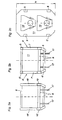
- the in Fig. 1 shown frame 2 of a locomotive has two support sections A, A ', which are mounted on chassis 3 with wheels 17. In the region of the middle section B, the frame 2 is bent downwards, whereby the driving characteristics of the rail vehicle are improved in particular on poor track systems and in tight curves and the accessibility to the Aggregates is facilitated.
- the Seltenteil 4 of the central portion B consists of a lower flange 6 and a top flange 5, which are interconnected by two webs 7.
- the webs 7 extend for reasons of static reasons of the substrate 6 obliquely upwards to the upper flange 5. It would also be possible, the webs 7 extend vertically or from the lower flange 6 obliquely inwards to the upper flange 5.
- the upper straps 5, 5 'and lower straps 6, 6' limit the machine room 11 laterally or up and down.
- the FrelIER which include the lower straps 6, 6 'and the upper straps 5, 5' between them, can remain free for reasons of better ventilation.
- the end faces of the central portion B, which are formed by the webs 7 and possibly existing cross members can be closed, for example by structure-supporting walls 9, so that the engine room 11 is closed in the direction of travel front and rear, while the bottom of the machine room 11 and the top of the engine room 11 - except for selective rain protection devices for Antriebseinhelten - completely open.
- the upper flange 5 of the side part 4 is longer than the lower flange 6 and projects beyond the central portion B in the support sections A, A 'of the frame 2, and is in its two end regions via webs 18 with side rails 19 of the support sections A. 'A' connected. These projecting into the support sections A, A 'parts of the upper flange 5 together with the webs 18, the side parts of the control room 12. At the end faces of the frame 2 as usual buffer 16 are arranged.
- Fig. 2a shows that the support section A has two lateral side members 19, which are interconnected via a cross member 8.
- the frame 2 in the support section A plate-shaped.
- the Fig. 2c shows in principle a cross section through the machine room 11 with drive units 10, 10 'arranged therein.
- the upper belts 5, 5' it is necessary for the upper belts 5, 5' to be arranged in the upper half, preferably in the uppermost third of the height of the rail vehicle 1.
- the drive units 10, 10 ' are mounted on the lower chords 6, 6' and the upper chords 5, 5 'of the frame 2 (not shown).
- the free space of the machine room 11 remaining laterally or above the drive units 10, 10 'can for example, be utilized for the arrangement of exhaust systems.
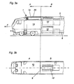
- Fig. 3a and 3b show the front in the direction of travel F support portion A and a part of the central portion B of the frame 2 in side view and top view.
- a wall 9 separates the engine room 11 from the control room 12, the lateral boundary is made by a side wall 14.
- a first cooling system 15 of a cooling device is arranged in the roof region of the carriage structure arranged above the support section A.
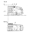
- a second cooling system 15 'of the cooling device is arranged in the roof region of the support section A' arranged behind the drive direction in the direction of travel ( Fig. 4a ).
- louvers 20 are arranged, which may be formed, for example, as air baffles or as fans, wherein at the front in the direction of travel cooling system 15, the wind is fed to the front side, while the introduction of the wind in the direction of travel F rear cooling system 15 'takes place mainly via the louver 20.
- switch cabinets 13 are arranged displaceably transversely to the longitudinal direction of the rail vehicle in the control room 12.
- this has the advantage that maintenance or service operations on the control cabinets 13 can be partly carried out from the outside, on the other hand
- Such a construction has the advantage of an enormous space savings, since the necessary space for movement to wait for the fixed cabinets 13 'in operation of the rail vehicle provides the space for the inserted cabinets 13.
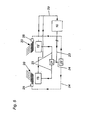
- Fig. 5 is schematically illustrated the operating principle of a cooling device according to the invention.
- the invention is based on the consideration that, as a result of the use of the airstream cooling medium for the cooling systems in the direction of travel front cooling system 15 must provide a much larger proportion of the overall performance of the cooling device, since the rear lying in the direction of travel cooling system 15 'naturally with less wind and in addition usually with the heated exhaust air from the engine room or the exhaust system is applied.
- the front and rear cooling system there are in principle two options.
- the coolant flow can be distributed differently to the front or rear cooling system.
- the cooling device has a control device 22, which is connected via a control line 24 to a valve 21 and outputs control signals to the valve 21.
- the valve 21 is connected on the input side via a coolant line 23 to a motor 10.
- the hot coolant flow flowing from the engine 10 to the valve 21 is divided differently between the cooling systems 15, 15 'as a function of the signal from the control device 22.
- the hot coolant thus flows via the coolant line 23 to the respective cooling systems 15, 15 ', where it is cooled and subsequently fed back to the engine 10, so that the coolant circuit closes.
- a basic idea of the invention therefore is to supply the front cooling system 15, which is more powerful than the rear cooling system 15 'due to the larger amount of cold air flow, to a larger amount of coolant flow to be cooled and thus to relieve the less powerful rear cooling system 15'.
- the cooling device on louvers 20, for example, from baffles or Fans can be formed.
- These louvers 20 are adjustable by means of an adjusting device 25, depending on the operating state, in particular the direction of travel, of the rail vehicle, wherein the adjusting device 25 is connected via a control line 24 to the control device 22.
- Optimum control of the cooling device that is to say an optimal distribution of the cooling power to be provided by the cooling device to the two cooling systems 15, 15 'as a function of their performance, can be achieved by a combination of both measures. That is, via the control device 22 on the one hand in the direction of travel front cooling system 15 is acted upon by a larger coolant flow and simultaneously applied in the direction of travel rear cooling system 15 'on the adjustable Heilieit Anlagenen 20 with increased airstream.
- Fig. 6 shows a perspective view of a frame 2 according to the invention, from which it can be seen that the downwardly cranked center portion of the frame is separated from the front support portion by a bulkhead 9. Between the upper chords 5, 5 'and the lower chords 6, 6' of the two side parts 4, 4 'are in addition to the oblique webs 7,7' additionally vertically extending webs 27, 27 'are arranged.
- these vertical connecting webs 27, 27 ' serve the arrangement of mounting brackets 26, 26'.
- the vertical webs 27, 27 ' which can be arranged both on the oblique webs 7, 7', the vertical webs 27, 27 'and on the upper and lower chords, the drive units 10 in the central portion of the Frame mounted. It has proved to be advantageous if all arranged on the drive units 10, 10 'connections are formed lying in a plane.
- a basic idea of the invention is a To provide a frame structure for a machine frame of a locomotive, which is substantially open at the top and bottom and in this way in addition to a good ventilation allows a particularly simple design.
- locomotives equipped with this frame according to the invention can be designed with only four axles, so that the total weight of such a powerful locomotive is approximately 80 t, while the usually equipped with six axes locomotives of this power class, the state of the art, a Total weight between 120 and 160 t.
Landscapes
- Engineering & Computer Science (AREA)
- Automation & Control Theory (AREA)
- Transportation (AREA)
- Mechanical Engineering (AREA)
- Electric Propulsion And Braking For Vehicles (AREA)
- Arrangement Or Mounting Of Propulsion Units For Vehicles (AREA)
- Lubricants (AREA)
- Diaphragms For Electromechanical Transducers (AREA)
- Inorganic Insulating Materials (AREA)
- Body Structure For Vehicles (AREA)
Applications Claiming Priority (2)
| Application Number | Priority Date | Filing Date | Title |
|---|---|---|---|
| AT9812003 | 2003-06-25 | ||
| EP04737355A EP1636081B1 (fr) | 2003-06-25 | 2004-06-25 | Locomotive |
Related Parent Applications (1)
| Application Number | Title | Priority Date | Filing Date |
|---|---|---|---|
| EP04737355.0 Division | 2004-06-25 |
Publications (3)
| Publication Number | Publication Date |
|---|---|
| EP2218623A2 true EP2218623A2 (fr) | 2010-08-18 |
| EP2218623A3 EP2218623A3 (fr) | 2010-10-20 |
| EP2218623B1 EP2218623B1 (fr) | 2011-09-07 |
Family
ID=33520105
Family Applications (2)
| Application Number | Title | Priority Date | Filing Date |
|---|---|---|---|
| EP10003093A Expired - Lifetime EP2218623B1 (fr) | 2003-06-25 | 2004-06-25 | Locomotive avec deux unités de traction supperposées |
| EP04737355A Expired - Lifetime EP1636081B1 (fr) | 2003-06-25 | 2004-06-25 | Locomotive |
Family Applications After (1)
| Application Number | Title | Priority Date | Filing Date |
|---|---|---|---|
| EP04737355A Expired - Lifetime EP1636081B1 (fr) | 2003-06-25 | 2004-06-25 | Locomotive |
Country Status (7)
| Country | Link |
|---|---|
| US (1) | US20060096347A1 (fr) |
| EP (2) | EP2218623B1 (fr) |
| CN (1) | CN1812906B (fr) |
| AT (2) | ATE469806T1 (fr) |
| CA (1) | CA2530016C (fr) |
| DE (1) | DE502004011238D1 (fr) |
| WO (1) | WO2004113145A2 (fr) |
Families Citing this family (5)
| Publication number | Priority date | Publication date | Assignee | Title |
|---|---|---|---|---|
| WO2008154748A1 (fr) * | 2007-06-20 | 2008-12-24 | Railpower Technologies Corp. | Groupe générateur transversal et conception modulaire pour la remise à neuf de locomotives |
| EP2093121A1 (fr) * | 2008-02-20 | 2009-08-26 | Alstom Transport S.A. | Véhicule sur rail, en particulier train automoteur, doté d'une ouverture dans le chassis pour le montage d'équipement |
| DE102011089812A1 (de) * | 2011-12-23 | 2013-06-27 | Richard Ag | Schaltvorrichtung für ein elektrisch angetriebenes Fahrzeug und Elektrofahrzeug |
| CN105253162B (zh) * | 2015-11-26 | 2017-11-03 | 南车戚墅堰机车有限公司 | 机车电阻制动底架 |
| CN105370381A (zh) * | 2015-11-30 | 2016-03-02 | 中国北车集团大连机车车辆有限公司 | 内走廊式内燃机车外置冷却装置 |
Citations (2)
| Publication number | Priority date | Publication date | Assignee | Title |
|---|---|---|---|---|
| US2205266A (en) | 1937-07-27 | 1940-06-18 | Gen Electric | Heat exchange apparatus |
| US6066897A (en) | 1996-01-19 | 2000-05-23 | Komatsu Ltd. | Automatic load distributing apparatus for generator and method of controlling same |
Family Cites Families (11)
| Publication number | Priority date | Publication date | Assignee | Title |
|---|---|---|---|---|
| CH391764A (de) * | 1962-04-11 | 1965-05-15 | Sulzer Ag | Grossdiesellokomotive |
| DE2707573A1 (de) * | 1977-02-22 | 1978-08-24 | Krupp Gmbh | Fachwerktraeger mit verbessertem kraftfluss |
| US5129328A (en) * | 1988-04-06 | 1992-07-14 | Donnelly Frank W | Gas turbine locomotive fueled by compressed natural Gas |
| DE4314405A1 (de) * | 1993-05-03 | 1994-11-10 | Goerlitz Waggonbau Gmbh | Doppelstock- Triebwagen zur Beförderung von Fahrgästen im Nebenbahnverkehr |
| DE9306853U1 (de) * | 1993-05-06 | 1993-07-08 | Schenk, Hans, 2300 Kiel | Wagenkasten mit Fachwerkseitenwand für einteilige und für Gelenkfahrzeuge |
| US5355806A (en) * | 1993-05-10 | 1994-10-18 | General Electric Company | Monocoque locomotive |
| US5566745A (en) * | 1993-05-10 | 1996-10-22 | General Electric Company | Shuttered radiator system with control |
| DE4424569A1 (de) * | 1994-07-13 | 1996-01-18 | Krauss Maffei Verkehrstechnik | Verfahren zur Herstellung einer Lokomotive |
| DE9415771U1 (de) * | 1994-09-30 | 1994-12-15 | ABB Henschel AG, 13509 Berlin | Schienengebundener Dieseltriebwagen |
| CN2338218Y (zh) * | 1998-07-14 | 1999-09-15 | 戚墅堰机车车辆厂 | 铁路机车 |
| US6397759B1 (en) * | 2000-05-11 | 2002-06-04 | Bombardier Inc. | Non-electric locomotive and enclosure for a turbine engine for a non-electric locomotive |
-
2004
- 2004-06-25 WO PCT/AT2004/000224 patent/WO2004113145A2/fr not_active Ceased
- 2004-06-25 DE DE502004011238T patent/DE502004011238D1/de not_active Expired - Lifetime
- 2004-06-25 CA CA2530016A patent/CA2530016C/fr not_active Expired - Fee Related
- 2004-06-25 EP EP10003093A patent/EP2218623B1/fr not_active Expired - Lifetime
- 2004-06-25 AT AT04737355T patent/ATE469806T1/de active
- 2004-06-25 CN CN2004800177203A patent/CN1812906B/zh not_active Expired - Fee Related
- 2004-06-25 EP EP04737355A patent/EP1636081B1/fr not_active Expired - Lifetime
- 2004-06-25 AT AT10003093T patent/ATE523406T1/de active
-
2005
- 2005-12-19 US US11/311,820 patent/US20060096347A1/en not_active Abandoned
Patent Citations (2)
| Publication number | Priority date | Publication date | Assignee | Title |
|---|---|---|---|---|
| US2205266A (en) | 1937-07-27 | 1940-06-18 | Gen Electric | Heat exchange apparatus |
| US6066897A (en) | 1996-01-19 | 2000-05-23 | Komatsu Ltd. | Automatic load distributing apparatus for generator and method of controlling same |
Also Published As
| Publication number | Publication date |
|---|---|
| CN1812906B (zh) | 2010-09-22 |
| WO2004113145A2 (fr) | 2004-12-29 |
| ATE523406T1 (de) | 2011-09-15 |
| DE502004011238D1 (de) | 2010-07-15 |
| CA2530016C (fr) | 2012-08-21 |
| US20060096347A1 (en) | 2006-05-11 |
| CA2530016A1 (fr) | 2004-12-29 |
| EP1636081B1 (fr) | 2010-06-02 |
| EP2218623B1 (fr) | 2011-09-07 |
| EP2218623A3 (fr) | 2010-10-20 |
| WO2004113145A3 (fr) | 2005-09-22 |
| EP1636081A2 (fr) | 2006-03-22 |
| CN1812906A (zh) | 2006-08-02 |
| ATE469806T1 (de) | 2010-06-15 |
Similar Documents
| Publication | Publication Date | Title |
|---|---|---|
| EP2619064B1 (fr) | Caisse pour une voiture ferroviaire et procédé pour sa production | |
| EP2543570B1 (fr) | Procédé de réalisation d'un véhicule ferroviaire, procédé de fabrication d'un véhicule ferroviaire et famille de véhicules ferroviaires | |
| EP3393883B1 (fr) | Véhicule ferroviaire, en particulier locomotive | |
| EP2305529A2 (fr) | Caisse de voiture modulaire | |
| EP2181030B1 (fr) | Véhicule ferroviaire avec un dispositif d'entraînement | |
| EP1369330B2 (fr) | Véhicule d'entretien | |
| EP2681094B1 (fr) | Véhicule ferroviaire comprenant un compartiment de réception en dessous du plancher | |
| EP1926648B1 (fr) | Construction d'une locomotive | |
| DE10248438A1 (de) | Energieversorgungseinrichtung für Schienenfahrzeuge | |
| EP1636081B1 (fr) | Locomotive | |
| EP2236379B1 (fr) | Véhicule ferroviaire à éléments multiples | |
| DE102011114354B3 (de) | Unterflurkühlanlage für ein Schienenfahrzeug | |
| EP4032776B1 (fr) | Voiture à double étage à alimentation en énergie, véhicule ferroviaire et procédé de fabrication d'une voiture à double étage | |
| EP0577938A1 (fr) | Voiture auto-motrice articulée pour trafic ferroviaire | |
| DE976897C (de) | Wagenkasten fuer Kraftwagen und aehnliche Fahrzeuge | |
| EP0536433B1 (fr) | Véhicule routier composé de plusieurs unités, notamment pour le transport urbain de personnes | |
| DE202005015144U1 (de) | Lokomotive | |
| EP4671076A1 (fr) | Boîtier destiné à être agencé sur une caisse d'un véhicule ferroviaire | |
| DE102006044396A1 (de) | Schienenfahrzeug mit einer Antriebseinrichtung | |
| DE8521256U1 (de) | Kanal-Reinigungsmaschine | |
| EP3437951A1 (fr) | Interface électrique dans un véhicule guidé sur rails | |
| DD292425A5 (de) | Biegesteife seitenwand fuer wagenkoerper, insbesondere von schnellfahrenden reisezugwagen | |
| DD200207B1 (de) | Untergestellvorbau von schienenfahrzeugen, insbesondere reisezugwagen |
Legal Events
| Date | Code | Title | Description |
|---|---|---|---|
| PUAI | Public reference made under article 153(3) epc to a published international application that has entered the european phase |
Free format text: ORIGINAL CODE: 0009012 |
|
| AC | Divisional application: reference to earlier application |
Ref document number: 1636081 Country of ref document: EP Kind code of ref document: P |
|
| AK | Designated contracting states |
Kind code of ref document: A2 Designated state(s): AT BE BG CH CY CZ DE DK EE ES FI FR GB GR HU IE IT LI LU MC NL PL PT RO SE SI SK TR |
|
| PUAL | Search report despatched |
Free format text: ORIGINAL CODE: 0009013 |
|
| AK | Designated contracting states |
Kind code of ref document: A3 Designated state(s): AT BE BG CH CY CZ DE DK EE ES FI FR GB GR HU IE IT LI LU MC NL PL PT RO SE SI SK TR |
|
| RIC1 | Information provided on ipc code assigned before grant |
Ipc: B60L 11/02 20060101ALI20100910BHEP Ipc: B61D 17/04 20060101AFI20100630BHEP |
|
| 17P | Request for examination filed |
Effective date: 20101009 |
|
| RIC1 | Information provided on ipc code assigned before grant |
Ipc: B60L 11/02 20060101ALI20110314BHEP Ipc: B61D 17/04 20060101AFI20110314BHEP |
|
| GRAP | Despatch of communication of intention to grant a patent |
Free format text: ORIGINAL CODE: EPIDOSNIGR1 |
|
| GRAS | Grant fee paid |
Free format text: ORIGINAL CODE: EPIDOSNIGR3 |
|
| GRAA | (expected) grant |
Free format text: ORIGINAL CODE: 0009210 |
|
| REG | Reference to a national code |
Ref country code: GB Ref legal event code: FG4D Free format text: NOT ENGLISH |
|
| REG | Reference to a national code |
Ref country code: CH Ref legal event code: EP |
|
| REG | Reference to a national code |
Ref country code: IE Ref legal event code: FG4D Free format text: LANGUAGE OF EP DOCUMENT: GERMAN |
|
| REG | Reference to a national code |
Ref country code: DE Ref legal event code: R096 Ref document number: 502004012851 Country of ref document: DE Effective date: 20111110 |
|
| REG | Reference to a national code |
Ref country code: CH Ref legal event code: NV Representative=s name: ZIMMERLI, WAGNER & PARTNER AG |
|
| REG | Reference to a national code |
Ref country code: NL Ref legal event code: VDEP Effective date: 20110907 |
|
| PG25 | Lapsed in a contracting state [announced via postgrant information from national office to epo] |
Ref country code: SE Free format text: LAPSE BECAUSE OF FAILURE TO SUBMIT A TRANSLATION OF THE DESCRIPTION OR TO PAY THE FEE WITHIN THE PRESCRIBED TIME-LIMIT Effective date: 20110907 Ref country code: FI Free format text: LAPSE BECAUSE OF FAILURE TO SUBMIT A TRANSLATION OF THE DESCRIPTION OR TO PAY THE FEE WITHIN THE PRESCRIBED TIME-LIMIT Effective date: 20110907 |
|
| PG25 | Lapsed in a contracting state [announced via postgrant information from national office to epo] |
Ref country code: GR Free format text: LAPSE BECAUSE OF FAILURE TO SUBMIT A TRANSLATION OF THE DESCRIPTION OR TO PAY THE FEE WITHIN THE PRESCRIBED TIME-LIMIT Effective date: 20111208 Ref country code: CY Free format text: LAPSE BECAUSE OF FAILURE TO SUBMIT A TRANSLATION OF THE DESCRIPTION OR TO PAY THE FEE WITHIN THE PRESCRIBED TIME-LIMIT Effective date: 20110907 Ref country code: SI Free format text: LAPSE BECAUSE OF FAILURE TO SUBMIT A TRANSLATION OF THE DESCRIPTION OR TO PAY THE FEE WITHIN THE PRESCRIBED TIME-LIMIT Effective date: 20110907 |
|
| REG | Reference to a national code |
Ref country code: IE Ref legal event code: FD4D |
|
| PG25 | Lapsed in a contracting state [announced via postgrant information from national office to epo] |
Ref country code: CZ Free format text: LAPSE BECAUSE OF FAILURE TO SUBMIT A TRANSLATION OF THE DESCRIPTION OR TO PAY THE FEE WITHIN THE PRESCRIBED TIME-LIMIT Effective date: 20110907 Ref country code: IE Free format text: LAPSE BECAUSE OF FAILURE TO SUBMIT A TRANSLATION OF THE DESCRIPTION OR TO PAY THE FEE WITHIN THE PRESCRIBED TIME-LIMIT Effective date: 20110907 Ref country code: SK Free format text: LAPSE BECAUSE OF FAILURE TO SUBMIT A TRANSLATION OF THE DESCRIPTION OR TO PAY THE FEE WITHIN THE PRESCRIBED TIME-LIMIT Effective date: 20110907 |
|
| PG25 | Lapsed in a contracting state [announced via postgrant information from national office to epo] |
Ref country code: NL Free format text: LAPSE BECAUSE OF FAILURE TO SUBMIT A TRANSLATION OF THE DESCRIPTION OR TO PAY THE FEE WITHIN THE PRESCRIBED TIME-LIMIT Effective date: 20110907 Ref country code: PT Free format text: LAPSE BECAUSE OF FAILURE TO SUBMIT A TRANSLATION OF THE DESCRIPTION OR TO PAY THE FEE WITHIN THE PRESCRIBED TIME-LIMIT Effective date: 20120109 Ref country code: EE Free format text: LAPSE BECAUSE OF FAILURE TO SUBMIT A TRANSLATION OF THE DESCRIPTION OR TO PAY THE FEE WITHIN THE PRESCRIBED TIME-LIMIT Effective date: 20110907 Ref country code: PL Free format text: LAPSE BECAUSE OF FAILURE TO SUBMIT A TRANSLATION OF THE DESCRIPTION OR TO PAY THE FEE WITHIN THE PRESCRIBED TIME-LIMIT Effective date: 20110907 Ref country code: RO Free format text: LAPSE BECAUSE OF FAILURE TO SUBMIT A TRANSLATION OF THE DESCRIPTION OR TO PAY THE FEE WITHIN THE PRESCRIBED TIME-LIMIT Effective date: 20110907 Ref country code: IT Free format text: LAPSE BECAUSE OF FAILURE TO SUBMIT A TRANSLATION OF THE DESCRIPTION OR TO PAY THE FEE WITHIN THE PRESCRIBED TIME-LIMIT Effective date: 20110907 |
|
| PLBI | Opposition filed |
Free format text: ORIGINAL CODE: 0009260 |
|
| PLAX | Notice of opposition and request to file observation + time limit sent |
Free format text: ORIGINAL CODE: EPIDOSNOBS2 |
|
| 26 | Opposition filed |
Opponent name: SIEMENS AG Effective date: 20120607 |
|
| PG25 | Lapsed in a contracting state [announced via postgrant information from national office to epo] |
Ref country code: DK Free format text: LAPSE BECAUSE OF FAILURE TO SUBMIT A TRANSLATION OF THE DESCRIPTION OR TO PAY THE FEE WITHIN THE PRESCRIBED TIME-LIMIT Effective date: 20110907 |
|
| REG | Reference to a national code |
Ref country code: DE Ref legal event code: R026 Ref document number: 502004012851 Country of ref document: DE Effective date: 20120607 |
|
| PLBB | Reply of patent proprietor to notice(s) of opposition received |
Free format text: ORIGINAL CODE: EPIDOSNOBS3 |
|
| BERE | Be: lapsed |
Owner name: EVOINVENT A.G. Effective date: 20120630 |
|
| PG25 | Lapsed in a contracting state [announced via postgrant information from national office to epo] |
Ref country code: MC Free format text: LAPSE BECAUSE OF NON-PAYMENT OF DUE FEES Effective date: 20120630 |
|
| GBPC | Gb: european patent ceased through non-payment of renewal fee |
Effective date: 20120625 |
|
| PG25 | Lapsed in a contracting state [announced via postgrant information from national office to epo] |
Ref country code: BE Free format text: LAPSE BECAUSE OF NON-PAYMENT OF DUE FEES Effective date: 20120630 Ref country code: GB Free format text: LAPSE BECAUSE OF NON-PAYMENT OF DUE FEES Effective date: 20120625 Ref country code: ES Free format text: LAPSE BECAUSE OF FAILURE TO SUBMIT A TRANSLATION OF THE DESCRIPTION OR TO PAY THE FEE WITHIN THE PRESCRIBED TIME-LIMIT Effective date: 20111218 |
|
| PG25 | Lapsed in a contracting state [announced via postgrant information from national office to epo] |
Ref country code: BG Free format text: LAPSE BECAUSE OF FAILURE TO SUBMIT A TRANSLATION OF THE DESCRIPTION OR TO PAY THE FEE WITHIN THE PRESCRIBED TIME-LIMIT Effective date: 20111207 |
|
| REG | Reference to a national code |
Ref country code: CH Ref legal event code: NV Representative=s name: WAGNER PATENT AG, CH |
|
| PG25 | Lapsed in a contracting state [announced via postgrant information from national office to epo] |
Ref country code: TR Free format text: LAPSE BECAUSE OF FAILURE TO SUBMIT A TRANSLATION OF THE DESCRIPTION OR TO PAY THE FEE WITHIN THE PRESCRIBED TIME-LIMIT Effective date: 20110907 |
|
| PG25 | Lapsed in a contracting state [announced via postgrant information from national office to epo] |
Ref country code: LU Free format text: LAPSE BECAUSE OF NON-PAYMENT OF DUE FEES Effective date: 20120625 |
|
| PG25 | Lapsed in a contracting state [announced via postgrant information from national office to epo] |
Ref country code: HU Free format text: LAPSE BECAUSE OF FAILURE TO SUBMIT A TRANSLATION OF THE DESCRIPTION OR TO PAY THE FEE WITHIN THE PRESCRIBED TIME-LIMIT Effective date: 20040625 |
|
| REG | Reference to a national code |
Ref country code: DE Ref legal event code: R100 Ref document number: 502004012851 Country of ref document: DE |
|
| PLCK | Communication despatched that opposition was rejected |
Free format text: ORIGINAL CODE: EPIDOSNREJ1 |
|
| PLBN | Opposition rejected |
Free format text: ORIGINAL CODE: 0009273 |
|
| STAA | Information on the status of an ep patent application or granted ep patent |
Free format text: STATUS: OPPOSITION REJECTED |
|
| 27O | Opposition rejected |
Effective date: 20140930 |
|
| REG | Reference to a national code |
Ref country code: DE Ref legal event code: R100 Ref document number: 502004012851 Country of ref document: DE Effective date: 20140930 |
|
| REG | Reference to a national code |
Ref country code: FR Ref legal event code: PLFP Year of fee payment: 13 |
|
| REG | Reference to a national code |
Ref country code: FR Ref legal event code: PLFP Year of fee payment: 14 |
|
| REG | Reference to a national code |
Ref country code: FR Ref legal event code: PLFP Year of fee payment: 15 |
|
| PGFP | Annual fee paid to national office [announced via postgrant information from national office to epo] |
Ref country code: CH Payment date: 20180625 Year of fee payment: 15 |
|
| PGFP | Annual fee paid to national office [announced via postgrant information from national office to epo] |
Ref country code: AT Payment date: 20180626 Year of fee payment: 15 Ref country code: FR Payment date: 20180627 Year of fee payment: 15 |
|
| PGFP | Annual fee paid to national office [announced via postgrant information from national office to epo] |
Ref country code: DE Payment date: 20190628 Year of fee payment: 16 |
|
| REG | Reference to a national code |
Ref country code: CH Ref legal event code: PL |
|
| REG | Reference to a national code |
Ref country code: AT Ref legal event code: MM01 Ref document number: 523406 Country of ref document: AT Kind code of ref document: T Effective date: 20190625 |
|
| PG25 | Lapsed in a contracting state [announced via postgrant information from national office to epo] |
Ref country code: AT Free format text: LAPSE BECAUSE OF NON-PAYMENT OF DUE FEES Effective date: 20190625 |
|
| PG25 | Lapsed in a contracting state [announced via postgrant information from national office to epo] |
Ref country code: CH Free format text: LAPSE BECAUSE OF NON-PAYMENT OF DUE FEES Effective date: 20190630 Ref country code: LI Free format text: LAPSE BECAUSE OF NON-PAYMENT OF DUE FEES Effective date: 20190630 |
|
| PG25 | Lapsed in a contracting state [announced via postgrant information from national office to epo] |
Ref country code: FR Free format text: LAPSE BECAUSE OF NON-PAYMENT OF DUE FEES Effective date: 20190630 |
|
| REG | Reference to a national code |
Ref country code: DE Ref legal event code: R119 Ref document number: 502004012851 Country of ref document: DE |
|
| PG25 | Lapsed in a contracting state [announced via postgrant information from national office to epo] |
Ref country code: DE Free format text: LAPSE BECAUSE OF NON-PAYMENT OF DUE FEES Effective date: 20210101 |