EP2218704A1 - Fermentationsanlage und Verfahren zum Betreiben einer solchen - Google Patents
Fermentationsanlage und Verfahren zum Betreiben einer solchen Download PDFInfo
- Publication number
- EP2218704A1 EP2218704A1 EP20090002122 EP09002122A EP2218704A1 EP 2218704 A1 EP2218704 A1 EP 2218704A1 EP 20090002122 EP20090002122 EP 20090002122 EP 09002122 A EP09002122 A EP 09002122A EP 2218704 A1 EP2218704 A1 EP 2218704A1
- Authority
- EP
- European Patent Office
- Prior art keywords
- fermenter
- fermentation
- fermentation material
- conveying element
- predetermined
- Prior art date
- Legal status (The legal status is an assumption and is not a legal conclusion. Google has not performed a legal analysis and makes no representation as to the accuracy of the status listed.)
- Granted
Links
Images



Classifications
-
- C—CHEMISTRY; METALLURGY
- C12—BIOCHEMISTRY; BEER; SPIRITS; WINE; VINEGAR; MICROBIOLOGY; ENZYMOLOGY; MUTATION OR GENETIC ENGINEERING
- C12M—APPARATUS FOR ENZYMOLOGY OR MICROBIOLOGY; APPARATUS FOR CULTURING MICROORGANISMS FOR PRODUCING BIOMASS, FOR GROWING CELLS OR FOR OBTAINING FERMENTATION OR METABOLIC PRODUCTS, i.e. BIOREACTORS OR FERMENTERS
- C12M21/00—Bioreactors or fermenters specially adapted for specific uses
- C12M21/04—Bioreactors or fermenters specially adapted for specific uses for producing gas, e.g. biogas
-
- C—CHEMISTRY; METALLURGY
- C05—FERTILISERS; MANUFACTURE THEREOF
- C05F—ORGANIC FERTILISERS NOT COVERED BY SUBCLASSES C05B, C05C, e.g. FERTILISERS FROM WASTE OR REFUSE
- C05F17/00—Preparation of fertilisers characterised by biological or biochemical treatment steps, e.g. composting or fermentation
- C05F17/90—Apparatus therefor
- C05F17/921—Devices in which the material is conveyed essentially horizontally between inlet and discharge means
- C05F17/939—Means for mixing or moving with predetermined or fixed paths, e.g. rails or cables
-
- C—CHEMISTRY; METALLURGY
- C12—BIOCHEMISTRY; BEER; SPIRITS; WINE; VINEGAR; MICROBIOLOGY; ENZYMOLOGY; MUTATION OR GENETIC ENGINEERING
- C12M—APPARATUS FOR ENZYMOLOGY OR MICROBIOLOGY; APPARATUS FOR CULTURING MICROORGANISMS FOR PRODUCING BIOMASS, FOR GROWING CELLS OR FOR OBTAINING FERMENTATION OR METABOLIC PRODUCTS, i.e. BIOREACTORS OR FERMENTERS
- C12M33/00—Means for introduction, transport, positioning, extraction, harvesting, peeling or sampling of biological material in or from the apparatus
- C12M33/20—Ribbons
-
- Y—GENERAL TAGGING OF NEW TECHNOLOGICAL DEVELOPMENTS; GENERAL TAGGING OF CROSS-SECTIONAL TECHNOLOGIES SPANNING OVER SEVERAL SECTIONS OF THE IPC; TECHNICAL SUBJECTS COVERED BY FORMER USPC CROSS-REFERENCE ART COLLECTIONS [XRACs] AND DIGESTS
- Y02—TECHNOLOGIES OR APPLICATIONS FOR MITIGATION OR ADAPTATION AGAINST CLIMATE CHANGE
- Y02P—CLIMATE CHANGE MITIGATION TECHNOLOGIES IN THE PRODUCTION OR PROCESSING OF GOODS
- Y02P20/00—Technologies relating to chemical industry
- Y02P20/141—Feedstock
- Y02P20/145—Feedstock the feedstock being materials of biological origin
-
- Y—GENERAL TAGGING OF NEW TECHNOLOGICAL DEVELOPMENTS; GENERAL TAGGING OF CROSS-SECTIONAL TECHNOLOGIES SPANNING OVER SEVERAL SECTIONS OF THE IPC; TECHNICAL SUBJECTS COVERED BY FORMER USPC CROSS-REFERENCE ART COLLECTIONS [XRACs] AND DIGESTS
- Y02—TECHNOLOGIES OR APPLICATIONS FOR MITIGATION OR ADAPTATION AGAINST CLIMATE CHANGE
- Y02W—CLIMATE CHANGE MITIGATION TECHNOLOGIES RELATED TO WASTEWATER TREATMENT OR WASTE MANAGEMENT
- Y02W30/00—Technologies for solid waste management
- Y02W30/40—Bio-organic fraction processing; Production of fertilisers from the organic fraction of waste or refuse
Definitions
- the invention relates to a fermentation plant according to the preamble of claim 1 and a method for operating such.
- fermenters in the form of garages or boxes are usually used, which are fed with fermentation material.
- an opening is usually provided on the front side, through which the fermenter boxes are charged by means of a wheel loader.
- the invention is based on the object, a fermentation plant and a corresponding method of the aforementioned Specify type with which the mentioned disadvantages do not occur.
- the invention it is provided to carry out the feeding and distribution in the fermenter by means of a distributor which is displaceable in the longitudinal direction of the fermenter.
- a distributor which is displaceable in the longitudinal direction of the fermenter.
- the volume above the fermentation material in the fermenter can be reduced and thus the ratio of the volume of the fermentation material to the total volume can be increased.
- this reduces the flushing volume, ie the volume which has to be exchanged via expensive flushing devices due to the above-mentioned introduction of nitrogen.
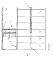
- FIG. 1 a typical construction of a fermentation plant according to the invention is shown. As a rule, this has one or, as shown, several fermenters F1-Fx, which are preferably designed as garage-shaped fermenter boxes.
- the fermenters F1-Fx have in their roof area feed openings 1, through which the fermentation material to be stored can be introduced from a preferably designed as a belt conveyor feed device 6 in the interior of the fermenter.
- a distributor device 4 Parallel to the end faces 3 of the fermenters F1-Fx, a distributor device 4 can be moved in the direction Y by means of a transport frame 8 and can thus be positioned in front of the frontal opening (item 3) of a selected fermenter F1-Fx to be charged become.
- the distribution device is designed so that it can be introduced from the transport frame 8 in the longitudinal direction X of the fermenter F1-Fx in this.
- the distributor 4 has a conveying element 5, which takes over the fermentation material to be stored in the fermenter F1-Fx from the charging device 6 and drops it in the fermenter F1-Fx.
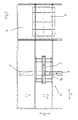
- the transport device 8 is displaceable in a corridor 7 and is moved in front of the fermenter F2, the distributor 4 is retracted in the X direction in the fermenter F2, so that a portion of the conveyor 5 is below the feed opening 1.
- the charging device 6 is placed with its discharge end over the opening 1, so that fermentation material from the charging device 6 through the opening 1 on the conveyor 5 falls.
- the conveyor is movable together with the distributor in the longitudinal direction X of the fermenter F2, also can the conveyor 5 move transversely to the longitudinal direction of the distributor 4, so that when filling the fermenter each point in the fermenter F2 can be approached, so that a homogeneous distribution of the fermentation material in the fermenter F2 is possible.
- the feed process with this measure is fully automated.
- the conveyor 5 can be moved in two directions.
- FIG. 3 shows the empty fermenter immediately before the feed.
- the transport device 8 is located with the Distributor 4 in the corridor 7 in front of the fermenter Fx.
- a running rail 9 is preferably provided at the level of the distributor 4, on which the distributor 4 can be moved back and forth in the longitudinal direction X of the fermenter Fx.
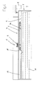
- FIG. 4 shows the filling process in longitudinal section through the fermenter.
- the distributor 4 has rollers 4 b, with which it rests on the rails 9.
- the fermentation material 10 discharged from the feed device 6 through the feed opening 1 reaches the conveyor 5 and from the end section thereof into the fermenter.
- the conveyor 5 is moved in the fermenter in a plane parallel to the ground, so that a uniform distribution of the fermentation material 10 in the fermenter is possible.
- the distribution of the fermentation material in the fermenter can also be done alternatively by a modified conveyor 5, which in the FIGS. 6 and 7 is shown schematically.
- the conveyor 5 has in the longitudinal direction X of the fermenter telescoping conveyor sections 5b, 5c, 5d, which are displaceable relative to the transport device 8 and can be extended into the fermenter into it.
- a pivotable discharge section 5a is provided, which can be about an axis Sy parallel to the bottom 11 and perpendicular to the axis Sz of the fermenter and pivot about an axis Sz vertical to the fermenter bottom, so that together with the Adjustment of the conveyor in the X direction each point in the fermenter with the discharge section 5a can be achieved.
Landscapes
- Health & Medical Sciences (AREA)
- Life Sciences & Earth Sciences (AREA)
- Chemical & Material Sciences (AREA)
- Engineering & Computer Science (AREA)
- Organic Chemistry (AREA)
- Molecular Biology (AREA)
- Zoology (AREA)
- Wood Science & Technology (AREA)
- Bioinformatics & Cheminformatics (AREA)
- Biotechnology (AREA)
- Genetics & Genomics (AREA)
- Microbiology (AREA)
- Biochemistry (AREA)
- General Engineering & Computer Science (AREA)
- Sustainable Development (AREA)
- Biomedical Technology (AREA)
- General Health & Medical Sciences (AREA)
- General Chemical & Material Sciences (AREA)
- Oil, Petroleum & Natural Gas (AREA)
- Chemical Kinetics & Catalysis (AREA)
- Processing Of Solid Wastes (AREA)
- Apparatus Associated With Microorganisms And Enzymes (AREA)
- Fertilizers (AREA)
Abstract
Description
- Die Erfindung betrifft eine Fermentationsanlage nach dem Oberbegriff des Anspruchs 1 und ein Verfahren zum Betreiben einer solchen.
- Bei entsprechenden Anlagen werden üblicherweise sogenannte Fermenter in Form von Garagen oder Boxen eingesetzt, die mit Fermentationsmaterial beschickt werden. Hierzu wird üblicherweise an der Stirnseite eine Öffnung vorgesehen, durch welche die Fermenterboxen mittels eines Radladers beschickt werden.
- Diese Art der Beschickung ist uneffektiv und aufwendig und erlaubt insbesondere keinen hohen Automatisierungsgrad. Zudem sammelt sich im Fermenter im Raum über dem Fermentationsmaterial durch vorhandene Luft so viel Stickstoff, dass es erforderlich ist, diesen Raum zumindest zu Beginn des Fermentationsprozesses zu spülen, damit die Stickstoffkonzentration einen kritischen Wert nicht übersteigt, was für aus dem Prozess gewonnenes Biogas nachteilig wäre. Das Spülen und Abführen von Stickstoff erfordert anlagentechnisch erhöhten Aufwand, weil außerhalb der Fermenter in der Anlage dafür vorgesehene Apparaturen und Anlagenteile vorgesehen werden müssen, die letztlich einen Teil der Kosten der Gesamtanlage ausmachen.
- Der Erfindung liegt die Aufgabe zugrunde, eine Fermentationsanlage und ein entsprechendes Verfahren der eingangs genannten Art anzugeben, mit denen die erwähnten Nachteile nicht auftreten.
- Gelöst wird diese Aufgabe durch eine Fermentationsanlage mit den Merkmalen des Anspruchs 1 sowie ein Verfahren zum Betreiben einer solchen mit den Merkmalen des Anspruchs 5. Vorteilhafte Ausführungsformen finden sich in den Unteransprüchen.
- Erfindungsgemäß ist vorgesehen, die Beschickung und Verteilung im Fermenter mittels einer Verteileinrichtung vorzunehmen, welche in Längsrichtung des Fermenters verschieblich ist. Hierdurch kann das Volumen oberhalb des Fermentationsmaterials im Fermenter verringert und damit das Verhältnis des Volumens des Fermentationsmaterials zum Gesamtvolumen erhöht werden. Gleichzeitig sinkt dadurch das Spülvolumen, also das Volumen, welches über kostenaufwendige Spüleinrichtungen aufgrund des oben erwähnten Stickstoffeintrags ausgetauscht werden muss. Mit der Erfindung ist es möglich, das Volumen oberhalb des Fermentationsmaterials so zu reduzieren, dass die Konzentration des Stickstoffs bezogen auf das Gesamtvolumen des gewonnenen Biogases unter 1% sinkt, so dass auf eine Spülung verzichtet werden kann.
- Die Erfindung wird nachfolgend anhand der
Figuren 1 bis 7 schematisch näher erläutert. - Figur 1 -
- zeigt eine Draufsicht auf einen Teil einer erfindungsegemäßen Fermentationsanlage,
- Figur 2 -
- ist eine Ausschnittvergrößerung eines Teils von
Figur 1 , - Figur 3 -
- zeigt eine Schnittansicht durch einen unbefüllten Fermenter der in
Figur 1 gezeigten Anlage, - Figur 4 -
- zeigt eine Schnittansicht durch einen erfindungsgemäß befüllten Fermenter,
- Figur 5 -
- zeigt eine Querschnittansicht durch die Fermenter,
- Figur 6 -
- zeigt eine zeigt Draufsicht auf einen Teil einer erfindungsgemäßen Fermentationsanlage mit einer alternativ ausgeführten Verteileinrichtung,
- Figur 7 -
- zeigt eine Längsschnittansicht durch einen mit der alternativen Verteileinrichtung befüllten Fermenter.
- In
Figur 1 ist ein typischer Aufbau einer erfindungsgemäßen Fermentationsanlage gezeigt. Diese weist in der Regel ein oder - wie gezeigt - mehrere Fermenter F1-Fx auf, welche bevorzugt als garagenförmige Fermenterboxen ausgebildet sind. Die Fermenter F1-Fx weisen in ihrem Dachbereich Beschickungsöffnungen 1 auf, durch welche das einzulagernde Fermentationsmaterial aus einer bevorzugt als Bandförderer ausgebildeten Beschickungsvorrichtung 6 in das Innere des Fermenters eingebracht werden kann. Parallel zu den Stirnseiten 3 der Fermenter F1-Fx ist eine Verteileinrichtung 4 in Richtung Y mittels eines Transportgestells 8 verfahrbar und kann so vor der stirnseitigen Öffnung (Pos. 3) eines ausgewählten zu beschickenden Fermenters F1-Fx positioniert werden. Die Verteileinrichtung ist so ausgebildet, dass sie aus dem Transportgestell 8 in Längsrichtung X der Fermenter F1-Fx in diese einbringbar ist. Die Verteileinrichtung 4 weist ein Förderelement 5 auf, welches das im Fermenter F1-Fx einzulagernde Fermentationsmaterial von der Beschickungsvorrichtung 6 übernimmt und im Fermenter F1-Fx abwirft. - Diese Situation ist in der Ausschnittvergrößerung in
Figur 2 gezeigt. Die Transportvorrichtung 8 ist in einem Korridor 7 verschieblich und wird vor den Fermenter F2 gefahren, die Verteileinrichtung 4 wird in X-Richtung in den Fermenter F2 eingefahren, so dass ein Abschnitt der Fördereinrichtung 5 unterhalb der Beschickungsöffnung 1 liegt. Die Beschickungsvorrichtung 6 wird mit ihrem Abwurfende über die Öffnung 1 platziert, so dass Fermentationsmaterial von der Beschickungsvorrichtung 6 durch die Öffnung 1 auf die Fördereinrichtung 5 fällt. Die Fördereinrichtung ist zusammen mit der Verteileinrichtung in Längsrichtung X des Fermenters F2 beweglich, zudem lässt sich die Fördereinrichtung 5 quer zur Längsrichtung an der Verteileinrichtung 4 verschieben, so dass beim Befüllen des Fermenters jeder Punkt im Fermenter F2 angefahren werden kann, so dass eine homogene Verteilung des Fermentationsmaterials im Fermenter F2 möglich ist. Zudem ist der Beschickungsprozess mit dieser Maßnahme vollständig automatisierbar. Bevorzugt kann die Fördereinrichtung 5 in zwei Richtungen bewegt werden. -
Figur 3 zeigt den leeren Fermenter unmittelbar vor der Beschickung. Die Transporteinrichtung 8 befindet sich mit der Verteileinrichtung 4 im Korridor 7 vor dem Fermenter Fx. Im Fermenter Fx ist bevorzugt in Höhe der Verteileinrichtung 4 eine Laufschiene 9 vorgesehen, auf der die Verteileinrichtung 4 in Längsrichtung X des Fermenters Fx in diesem hin und her bewegt werden kann. -
Figur 4 zeigt den Befüllvorgang im Längsschnitt durch den Fermenter. Die Verteileinrichtung 4 weist Rollen 4b auf, mit denen sie auf den Laufschienen 9 aufliegt. Das aus der Beschickungseinrichtung 6 durch die Beschickungsöffnung 1 abgeworfene Fermentationsmaterial 10 gelangt auf die Fördereinrichtung 5 und von deren Endabschnitt in den Fermenter. Dabei wird die Fördereinrichtung 5 im Fermenter in einer Ebene parallel zum Boden verschoben, so dass eine gleichmäßige Verteilung des Fermentionsmaterials 10 im Fermenter möglich ist. - Wie in
Figur 5 gezeigt, kann durch die flache Bauweise der Verteileinrichtung 4 der nicht mit dem Fermentationsmaterial 10 befüllbare Raum 12 im Gegensatz zu einer Radladerbeschickung verringert werden. So ist mit diesem Verfahren eine Verringerung des Spülvolumens 12 möglich, da das Fermentationsmaterial 10 bis zu einer Höhe in den Fermenter eingebracht werden kann, die über dem 0,7-fachen der Gesamtinnenhöhe G des Fermenters liegt. Der im Prozess vorhandene Stickstoff kann aufgrund des geringen Spülvolumens 12 daher im Vergleich zu herkömmlichen Verfahren deutlich reduziert werden. - Die Verteilung des Fermentationsmaterials im Fermenter kann auch alternativ durch eine modifizierte Fördereinrichtung 5 erfolgen, die in den
Figuren 6 und7 schematisch dargestellt wird. Die Fördereinrichtung 5 weist in Längsrichtung X des Fermenters teleskopierbare Förderabschnitte 5b, 5c, 5d auf, welche gegenüber der Transporteinrichtung 8 verschieblich sind und in den Fermenter hinein ausgefahren werden können. Am zum Fermenter hin gerichteten Ende der Fördereinrichtung 5 ist ein verschwenkbarer Abwurfabschnitt 5a vorgesehen, der sich um eine Achse Sy parallel zum Boden 11 bzw. senkrecht zur Achse Sz des Fermenters und um eine Achse Sz vertikal zum Fermenterboden verschwenken lässt, so dass zusammen mit der Verstellung der Fördereinrichtung in X-Richtung jeder Punkt im Fermenter mit dem Abwurfabschnitt 5a erreicht werden kann. Durch diese Maßnahme ist es möglich, die Beschickung ausschließlich von der Stirnseite 3 des Fermenters durchzuführen, Beschickungsöffnungen im Dach des Fermenters sind dann nicht erforderlich.
Claims (8)
- Fermentationsanlage mit wenigstens einem Fermenter (F1, F2, ..., Fx) zur Aufnahme von Fermentationsmaterial, wobei der wenigstens eine Fermenter (F1, F2, ..., Fx) ein boxenförmiger Fermenter (F1, F2, ..., Fx) mit wenigstens einer Öffnung (2) an der Stirnseite (3) ist, durch welche eine Verteileinrichtung (4) zum Verteilen von einzubringendem Fermentationsmaterial (10) in den Fermenter (F1, F2, ..., Fx) eingebracht und aus diesem entfernt werden kann,
dadurch gekennzeichnet,
dass die Verteileinrichtung (4) in Längsrichtung des Fermenters (F1, F2, ..., Fx) verschieblich gelagert ist und ein Förderelement (5) aufweist, welches das Fermentationsmaterial aufnimmt und an einer vorgegebenen Stelle im Fermenter (F1, F2, ..., Fx) abwirft, wobei das Förderelement (5) oder die Verteileinrichtung (4) in wenigstens einer Ebene parallel zum Boden des Fermenters (F1, F2, ..., Fx) beweglich gelagert ist. - Fermentationsanlage nach Anspruch 1,
dadurch gekennzeichnet,
dass das Förderelement (5) quer zur Längsrichtung (X) des Fermenters (F1, F2, ..., Fx) verschieblich ist. - Fermentationsanlage, nach einem der Ansprüche 1 oder 2,
dadurch gekennzeichnet,
dass eine Beschickungsöffnung (1) vorgesehen ist, durch welche in den Fermenter (F1, F2, ..., Fx) einzubringendes Fermentationsmaterial (10) der Verteileinrichtung (4) zugeführt werden kann. - Fermentationsanlage nach Anspruch 1, 2 oder 3,
dadurch gekennzeichnet,
dass das Förderelement (5) einen schwenkbaren Abwurfabschnitt (5a) aufweist, der um eine erste Achse (Sz) senkrecht zum Boden (11) des Fermenters (F1, F2, ..., Fx) schwenkbar gelagert ist. - Fermentationsanlage nach Anspruch 4,
dadurch gekennzeichnet,
dass der Abwurfabschnitt (5a) auch um eine Schwenkachse (Sy) senkrecht zur ersten Achse (Sz) verschwenkbar ist. - Fermentationsanlage nach einem der Ansprüche 1 bis 5,
dadurch gekennzeichnet,
dass die Beschickungsöffnung (1) im Dach des Fermenters (F1, F2, ..., Fx) vorgesehen ist und eine Beschickungsvorrichtung (6) vorgesehen ist, die so ausgelegt ist, dass sie eine vorgegebene Beschickungsöffnung (1) eines vorgegebenen Fermenters (F1, F2, ..., Fx) beschickt, um das Fermentationsmaterial an die jenseits der Beschickungsöffnung (1) im Fermenter (F1, F2, ..., Fx) positionierte Verteileinrichtung (4) zu übergeben. - Verfahren zum Betreiben einer Fermentationsanlage, insbesondere nach einem der vorherigen Ansprüche, bei welchem wenigstens ein Fermenter (F1, F2, ..., Fx) zur Aufnahme von Fermentationsmaterial eingesetzt wird, wobei vor dem Beginn des Fermentationsprozesses der Fermenter (F1, F2, ..., Fx) mit Fermentationsmaterial bis zu einer vorgegebenen Höhe (H) unterhalb der Gesamtinnenhöhe (G) des Fermenters (F1, F2, ..., Fx) beschickt wird,
dadurch gekennzeichnet,
dass die vorgegebene Höhe (H) so gewählt ist, dass die im anschließenden Fermentationsprozess vorhandene Menge an Stickstoff bzw. stickstoffhaltigen Substanzen einen vorgegebenen Grenzwert nicht übersteigt. - Verfahren nach Anspruch 7,
dadurch gekennzeichnet,
dass das Verhältnis der vorgegebenen Höhe (H) zur Gesamtinnenhöhe (G) größer als 0,7 beträgt.
Priority Applications (3)
| Application Number | Priority Date | Filing Date | Title |
|---|---|---|---|
| ES09002122.1T ES2537320T3 (es) | 2009-02-16 | 2009-02-16 | Instalación de fermentación y procedimiento para el funcionamiento de una instalación de este tipo |
| PL09002122T PL2218704T3 (pl) | 2009-02-16 | 2009-02-16 | Instalacja fermentacyjna i sposób jej eksploatacji |
| EP20090002122 EP2218704B1 (de) | 2009-02-16 | 2009-02-16 | Fermentationsanlage und Verfahren zum Betreiben einer solchen |
Applications Claiming Priority (1)
| Application Number | Priority Date | Filing Date | Title |
|---|---|---|---|
| EP20090002122 EP2218704B1 (de) | 2009-02-16 | 2009-02-16 | Fermentationsanlage und Verfahren zum Betreiben einer solchen |
Publications (2)
| Publication Number | Publication Date |
|---|---|
| EP2218704A1 true EP2218704A1 (de) | 2010-08-18 |
| EP2218704B1 EP2218704B1 (de) | 2015-02-25 |
Family
ID=40873522
Family Applications (1)
| Application Number | Title | Priority Date | Filing Date |
|---|---|---|---|
| EP20090002122 Active EP2218704B1 (de) | 2009-02-16 | 2009-02-16 | Fermentationsanlage und Verfahren zum Betreiben einer solchen |
Country Status (3)
| Country | Link |
|---|---|
| EP (1) | EP2218704B1 (de) |
| ES (1) | ES2537320T3 (de) |
| PL (1) | PL2218704T3 (de) |
Cited By (4)
| Publication number | Priority date | Publication date | Assignee | Title |
|---|---|---|---|---|
| CN102060584A (zh) * | 2010-11-26 | 2011-05-18 | 云南云叶化肥股份有限公司 | 一种有机肥发酵工艺 |
| CN102060586A (zh) * | 2010-11-26 | 2011-05-18 | 云南云叶化肥股份有限公司 | 一种有机肥发酵布料装置 |
| NL2008383C2 (nl) * | 2012-02-29 | 2013-09-02 | Peeters Landbouwmach | Inrichting voor het mengen van materiaal en werkwijze voor het toepassen van een dergelijke inrichting. |
| CN109078970A (zh) * | 2018-09-30 | 2018-12-25 | 江苏雪枫环保科技有限公司 | 一种发酵罐喂料系统 |
Citations (9)
| Publication number | Priority date | Publication date | Assignee | Title |
|---|---|---|---|---|
| GB717785A (en) * | 1951-04-20 | 1954-11-03 | Nicolo Boggiano Pico | Method of and installation for the conversion of household refuse and organic waste into sterile or fertilising matters |
| EP0501319A1 (de) * | 1991-02-25 | 1992-09-02 | THÖNI INDUSTRIEBETRIEBE GESELLSCHAFT m.b.H. | Kompostieranlage zur Kompostierung von Abfällen |
| JPH0834523A (ja) * | 1994-07-22 | 1996-02-06 | Raihou:Kk | ゴミ搬送用自動化ロボット |
| EP0799812A1 (de) * | 1996-04-03 | 1997-10-08 | CT Umwelttechnik AG | Beschickungseinrichtung für eine Vergärungsanlage |
| WO2002006439A2 (de) * | 2000-07-14 | 2002-01-24 | Bekon Energy Technologies Gmbh | Bioreaktor zur methanisierung von biomasse und eine biogasanlage zur erzeugung von thermischer, elektrischer oder mechanischer energie aus biomasse mit einem solchen bioreaktor sowie verfahren zur regelung und steuerung einer solchen biogasanlage |
| DE102004009161A1 (de) * | 2004-02-25 | 2005-09-15 | HöFer Bioreact GmbH | Optimierte Induktion und gerichtete selektive Festphasen-Kultivierung stabiler, mikrobieller Mischkulturen zur kontinuierlichen Herstellung definierter Enzym- und Metabolitgemische und Verfahren und Vorrichtung dazu |
| ES2245210A1 (es) * | 2004-01-14 | 2005-12-16 | Industrias Leblan, S.L. | Sistema de carga automatica de tuneles de fermentacion de materia organica. |
| EP1681344A1 (de) * | 2005-01-14 | 2006-07-19 | U.T.S. Umwelt-Technik-Süd GmbH | Feststoffbeschickungsvorrichtung an einem Fermenter einer Biogasanlage |
| EP1970435A1 (de) * | 2007-03-13 | 2008-09-17 | MARATON Energie Technik GmbH | Vorrichtung zur Gärgutbeschickung einer Gäranlage |
Family Cites Families (2)
| Publication number | Priority date | Publication date | Assignee | Title |
|---|---|---|---|---|
| DE102007015981A1 (de) * | 2007-04-03 | 2008-10-16 | Erich Stallkamp Esta Gmbh | Biogasanlage |
| DE102007029700A1 (de) * | 2007-06-27 | 2009-01-08 | Michael Feldmann | Biomasse-Kraftwerk |
-
2009
- 2009-02-16 EP EP20090002122 patent/EP2218704B1/de active Active
- 2009-02-16 ES ES09002122.1T patent/ES2537320T3/es active Active
- 2009-02-16 PL PL09002122T patent/PL2218704T3/pl unknown
Patent Citations (9)
| Publication number | Priority date | Publication date | Assignee | Title |
|---|---|---|---|---|
| GB717785A (en) * | 1951-04-20 | 1954-11-03 | Nicolo Boggiano Pico | Method of and installation for the conversion of household refuse and organic waste into sterile or fertilising matters |
| EP0501319A1 (de) * | 1991-02-25 | 1992-09-02 | THÖNI INDUSTRIEBETRIEBE GESELLSCHAFT m.b.H. | Kompostieranlage zur Kompostierung von Abfällen |
| JPH0834523A (ja) * | 1994-07-22 | 1996-02-06 | Raihou:Kk | ゴミ搬送用自動化ロボット |
| EP0799812A1 (de) * | 1996-04-03 | 1997-10-08 | CT Umwelttechnik AG | Beschickungseinrichtung für eine Vergärungsanlage |
| WO2002006439A2 (de) * | 2000-07-14 | 2002-01-24 | Bekon Energy Technologies Gmbh | Bioreaktor zur methanisierung von biomasse und eine biogasanlage zur erzeugung von thermischer, elektrischer oder mechanischer energie aus biomasse mit einem solchen bioreaktor sowie verfahren zur regelung und steuerung einer solchen biogasanlage |
| ES2245210A1 (es) * | 2004-01-14 | 2005-12-16 | Industrias Leblan, S.L. | Sistema de carga automatica de tuneles de fermentacion de materia organica. |
| DE102004009161A1 (de) * | 2004-02-25 | 2005-09-15 | HöFer Bioreact GmbH | Optimierte Induktion und gerichtete selektive Festphasen-Kultivierung stabiler, mikrobieller Mischkulturen zur kontinuierlichen Herstellung definierter Enzym- und Metabolitgemische und Verfahren und Vorrichtung dazu |
| EP1681344A1 (de) * | 2005-01-14 | 2006-07-19 | U.T.S. Umwelt-Technik-Süd GmbH | Feststoffbeschickungsvorrichtung an einem Fermenter einer Biogasanlage |
| EP1970435A1 (de) * | 2007-03-13 | 2008-09-17 | MARATON Energie Technik GmbH | Vorrichtung zur Gärgutbeschickung einer Gäranlage |
Cited By (7)
| Publication number | Priority date | Publication date | Assignee | Title |
|---|---|---|---|---|
| CN102060584A (zh) * | 2010-11-26 | 2011-05-18 | 云南云叶化肥股份有限公司 | 一种有机肥发酵工艺 |
| CN102060586A (zh) * | 2010-11-26 | 2011-05-18 | 云南云叶化肥股份有限公司 | 一种有机肥发酵布料装置 |
| CN102060584B (zh) * | 2010-11-26 | 2013-03-20 | 云南云叶化肥股份有限公司 | 一种有机肥发酵工艺 |
| CN102060586B (zh) * | 2010-11-26 | 2013-04-10 | 云南云叶化肥股份有限公司 | 一种有机肥发酵布料装置 |
| NL2008383C2 (nl) * | 2012-02-29 | 2013-09-02 | Peeters Landbouwmach | Inrichting voor het mengen van materiaal en werkwijze voor het toepassen van een dergelijke inrichting. |
| EP2633768A1 (de) * | 2012-02-29 | 2013-09-04 | Peeters Landbouwmachines B.V. | Vorrichtung zum Mischen von Material und Verfahren zum Betreiben einer solchen Vorrichtung |
| CN109078970A (zh) * | 2018-09-30 | 2018-12-25 | 江苏雪枫环保科技有限公司 | 一种发酵罐喂料系统 |
Also Published As
| Publication number | Publication date |
|---|---|
| EP2218704B1 (de) | 2015-02-25 |
| ES2537320T3 (es) | 2015-06-05 |
| PL2218704T3 (pl) | 2015-07-31 |
Similar Documents
| Publication | Publication Date | Title |
|---|---|---|
| EP2816305A1 (de) | Vorrichtung zum Be- und Entladen einer Stellplatte einer Gefriertrocknungsanlage und ein Verfahren hierfür | |
| EP3315420B1 (de) | Tiefziehverpackungsmaschine | |
| EP0612481A2 (de) | Einrichtung zum Transport und zur Bevorratung von Zigaretten | |
| EP2218704B1 (de) | Fermentationsanlage und Verfahren zum Betreiben einer solchen | |
| EP3686135A1 (de) | Vorrichtung zum kommissionieren von ladegut auf paletten und verfahren zum kommissionieren | |
| AT523802B1 (de) | Mattenschweißanlage zur Herstellung von Betonstahlmatten | |
| DE102017110995A1 (de) | Vorpresse und System zum kontinuierlichen Herstellen von Werkstoffplatten, Verfahren zum Einbringen oder Entnehmen des Pressenbandes und Transportvorrichtung zum Aufnehmen des Pressenbandes | |
| EP2784006A1 (de) | Kommissioniersystem | |
| EP2540645A1 (de) | Vorrichtung zum Umladen von Abfällen | |
| EP1608557A1 (de) | Übergabestelle in einem kommissioniersystem | |
| AT511698B1 (de) | Verfahren zur planumsanierung | |
| EP2162022A1 (de) | Befüllmagazin zum befüllen von schachtschragen sowie befüllstation mit einem solchen befüllmagazin | |
| DE202008004922U1 (de) | Beschickungssystem für Rohrbündelreaktoren | |
| DE2812145C2 (de) | ||
| DE102013100815A1 (de) | Schragenentleereinrichtung und Verfahren zum automatischen Entleeren von mit stabförmigen Artikeln gefüllten Schragen in eine Produktionsmaschine der Tabak verarbeitenden Industrie sowie eine Produktionsanordnung mit einer Produktionsmaschine und mindestens zwei Schragenentleereinrichtungen | |
| DE10330949A1 (de) | Verfahren und Anlage zur automatisierten Annahme und Weiterverarbeitung von Trauben | |
| AT13016U1 (de) | Vorrichtung und Verfahren zur selektiven, sortenreinen Teilerückführung | |
| EP0121659B1 (de) | Vorrichtung zur Rückverladung von losem Schüttgut | |
| DE102023127255B4 (de) | Verfahren und Vorrichtung zum Kommissionieren von Stückgut in einen Rollbehälter | |
| DE102007022845A1 (de) | Befüllmagazin zum Befüllen von Schachtschragen sowie Befüllstation mit einem solchen Befüllmagazin | |
| DE3521781C1 (de) | Beschickungsvorrichtung | |
| WO2011026484A1 (de) | Abdichtvorrichtung für eine mit kohlekuchen beschickte verkokungsanlage | |
| DE19727592C2 (de) | Befüllanlage mit einer mobilen Befülleinrichtung | |
| DE202017103053U1 (de) | Vorpresse und System zum kontinuierlichen Herstellen von Werkstoffplatten und Transportvorrichtung zum Aufnehmen des Pressenbandes | |
| EP2470329B1 (de) | Strahlmittelspeicher |
Legal Events
| Date | Code | Title | Description |
|---|---|---|---|
| PUAI | Public reference made under article 153(3) epc to a published international application that has entered the european phase |
Free format text: ORIGINAL CODE: 0009012 |
|
| AK | Designated contracting states |
Kind code of ref document: A1 Designated state(s): AT BE BG CH CY CZ DE DK EE ES FI FR GB GR HR HU IE IS IT LI LT LU LV MC MK MT NL NO PL PT RO SE SI SK TR |
|
| AX | Request for extension of the european patent |
Extension state: AL BA RS |
|
| 17P | Request for examination filed |
Effective date: 20110216 |
|
| AKX | Designation fees paid |
Designated state(s): AT BE BG CH CY CZ DE DK EE ES FI FR GB GR HR HU IE IS IT LI LT LU LV MC MK MT NL NO PL PT RO SE SI SK TR |
|
| 17Q | First examination report despatched |
Effective date: 20130103 |
|
| GRAP | Despatch of communication of intention to grant a patent |
Free format text: ORIGINAL CODE: EPIDOSNIGR1 |
|
| INTG | Intention to grant announced |
Effective date: 20141016 |
|
| GRAS | Grant fee paid |
Free format text: ORIGINAL CODE: EPIDOSNIGR3 |
|
| GRAA | (expected) grant |
Free format text: ORIGINAL CODE: 0009210 |
|
| AK | Designated contracting states |
Kind code of ref document: B1 Designated state(s): AT BE BG CH CY CZ DE DK EE ES FI FR GB GR HR HU IE IS IT LI LT LU LV MC MK MT NL NO PL PT RO SE SI SK TR |
|
| REG | Reference to a national code |
Ref country code: GB Ref legal event code: FG4D Free format text: NOT ENGLISH |
|
| REG | Reference to a national code |
Ref country code: CH Ref legal event code: EP |
|
| REG | Reference to a national code |
Ref country code: IE Ref legal event code: FG4D Free format text: LANGUAGE OF EP DOCUMENT: GERMAN |
|
| REG | Reference to a national code |
Ref country code: DE Ref legal event code: R096 Ref document number: 502009010631 Country of ref document: DE Effective date: 20150409 |
|
| REG | Reference to a national code |
Ref country code: AT Ref legal event code: REF Ref document number: 711809 Country of ref document: AT Kind code of ref document: T Effective date: 20150415 |
|
| REG | Reference to a national code |
Ref country code: ES Ref legal event code: FG2A Ref document number: 2537320 Country of ref document: ES Kind code of ref document: T3 Effective date: 20150605 |
|
| REG | Reference to a national code |
Ref country code: NL Ref legal event code: VDEP Effective date: 20150225 |
|
| REG | Reference to a national code |
Ref country code: LT Ref legal event code: MG4D |
|
| PG25 | Lapsed in a contracting state [announced via postgrant information from national office to epo] |
Ref country code: SE Free format text: LAPSE BECAUSE OF FAILURE TO SUBMIT A TRANSLATION OF THE DESCRIPTION OR TO PAY THE FEE WITHIN THE PRESCRIBED TIME-LIMIT Effective date: 20150225 Ref country code: HR Free format text: LAPSE BECAUSE OF FAILURE TO SUBMIT A TRANSLATION OF THE DESCRIPTION OR TO PAY THE FEE WITHIN THE PRESCRIBED TIME-LIMIT Effective date: 20150225 Ref country code: FI Free format text: LAPSE BECAUSE OF FAILURE TO SUBMIT A TRANSLATION OF THE DESCRIPTION OR TO PAY THE FEE WITHIN THE PRESCRIBED TIME-LIMIT Effective date: 20150225 Ref country code: LT Free format text: LAPSE BECAUSE OF FAILURE TO SUBMIT A TRANSLATION OF THE DESCRIPTION OR TO PAY THE FEE WITHIN THE PRESCRIBED TIME-LIMIT Effective date: 20150225 Ref country code: NO Free format text: LAPSE BECAUSE OF FAILURE TO SUBMIT A TRANSLATION OF THE DESCRIPTION OR TO PAY THE FEE WITHIN THE PRESCRIBED TIME-LIMIT Effective date: 20150525 |
|
| REG | Reference to a national code |
Ref country code: PL Ref legal event code: T3 |
|
| PG25 | Lapsed in a contracting state [announced via postgrant information from national office to epo] |
Ref country code: GR Free format text: LAPSE BECAUSE OF FAILURE TO SUBMIT A TRANSLATION OF THE DESCRIPTION OR TO PAY THE FEE WITHIN THE PRESCRIBED TIME-LIMIT Effective date: 20150526 Ref country code: IS Free format text: LAPSE BECAUSE OF FAILURE TO SUBMIT A TRANSLATION OF THE DESCRIPTION OR TO PAY THE FEE WITHIN THE PRESCRIBED TIME-LIMIT Effective date: 20150625 Ref country code: LV Free format text: LAPSE BECAUSE OF FAILURE TO SUBMIT A TRANSLATION OF THE DESCRIPTION OR TO PAY THE FEE WITHIN THE PRESCRIBED TIME-LIMIT Effective date: 20150225 |
|
| PG25 | Lapsed in a contracting state [announced via postgrant information from national office to epo] |
Ref country code: NL Free format text: LAPSE BECAUSE OF FAILURE TO SUBMIT A TRANSLATION OF THE DESCRIPTION OR TO PAY THE FEE WITHIN THE PRESCRIBED TIME-LIMIT Effective date: 20150225 |
|
| PG25 | Lapsed in a contracting state [announced via postgrant information from national office to epo] |
Ref country code: EE Free format text: LAPSE BECAUSE OF FAILURE TO SUBMIT A TRANSLATION OF THE DESCRIPTION OR TO PAY THE FEE WITHIN THE PRESCRIBED TIME-LIMIT Effective date: 20150225 Ref country code: RO Free format text: LAPSE BECAUSE OF FAILURE TO SUBMIT A TRANSLATION OF THE DESCRIPTION OR TO PAY THE FEE WITHIN THE PRESCRIBED TIME-LIMIT Effective date: 20150225 Ref country code: DK Free format text: LAPSE BECAUSE OF FAILURE TO SUBMIT A TRANSLATION OF THE DESCRIPTION OR TO PAY THE FEE WITHIN THE PRESCRIBED TIME-LIMIT Effective date: 20150225 Ref country code: SK Free format text: LAPSE BECAUSE OF FAILURE TO SUBMIT A TRANSLATION OF THE DESCRIPTION OR TO PAY THE FEE WITHIN THE PRESCRIBED TIME-LIMIT Effective date: 20150225 Ref country code: CZ Free format text: LAPSE BECAUSE OF FAILURE TO SUBMIT A TRANSLATION OF THE DESCRIPTION OR TO PAY THE FEE WITHIN THE PRESCRIBED TIME-LIMIT Effective date: 20150225 |
|
| REG | Reference to a national code |
Ref country code: DE Ref legal event code: R097 Ref document number: 502009010631 Country of ref document: DE |
|
| PLBE | No opposition filed within time limit |
Free format text: ORIGINAL CODE: 0009261 |
|
| STAA | Information on the status of an ep patent application or granted ep patent |
Free format text: STATUS: NO OPPOSITION FILED WITHIN TIME LIMIT |
|
| REG | Reference to a national code |
Ref country code: FR Ref legal event code: PLFP Year of fee payment: 8 |
|
| 26N | No opposition filed |
Effective date: 20151126 |
|
| PG25 | Lapsed in a contracting state [announced via postgrant information from national office to epo] |
Ref country code: SI Free format text: LAPSE BECAUSE OF FAILURE TO SUBMIT A TRANSLATION OF THE DESCRIPTION OR TO PAY THE FEE WITHIN THE PRESCRIBED TIME-LIMIT Effective date: 20150225 |
|
| PG25 | Lapsed in a contracting state [announced via postgrant information from national office to epo] |
Ref country code: BE Free format text: LAPSE BECAUSE OF NON-PAYMENT OF DUE FEES Effective date: 20160229 |
|
| PG25 | Lapsed in a contracting state [announced via postgrant information from national office to epo] |
Ref country code: LU Free format text: LAPSE BECAUSE OF FAILURE TO SUBMIT A TRANSLATION OF THE DESCRIPTION OR TO PAY THE FEE WITHIN THE PRESCRIBED TIME-LIMIT Effective date: 20160216 Ref country code: MC Free format text: LAPSE BECAUSE OF FAILURE TO SUBMIT A TRANSLATION OF THE DESCRIPTION OR TO PAY THE FEE WITHIN THE PRESCRIBED TIME-LIMIT Effective date: 20150225 |
|
| REG | Reference to a national code |
Ref country code: CH Ref legal event code: PL |
|
| PG25 | Lapsed in a contracting state [announced via postgrant information from national office to epo] |
Ref country code: CH Free format text: LAPSE BECAUSE OF NON-PAYMENT OF DUE FEES Effective date: 20160229 Ref country code: LI Free format text: LAPSE BECAUSE OF NON-PAYMENT OF DUE FEES Effective date: 20160229 |
|
| REG | Reference to a national code |
Ref country code: IE Ref legal event code: MM4A |
|
| PG25 | Lapsed in a contracting state [announced via postgrant information from national office to epo] |
Ref country code: IE Free format text: LAPSE BECAUSE OF NON-PAYMENT OF DUE FEES Effective date: 20160216 |
|
| REG | Reference to a national code |
Ref country code: FR Ref legal event code: PLFP Year of fee payment: 9 |
|
| PG25 | Lapsed in a contracting state [announced via postgrant information from national office to epo] |
Ref country code: MT Free format text: LAPSE BECAUSE OF FAILURE TO SUBMIT A TRANSLATION OF THE DESCRIPTION OR TO PAY THE FEE WITHIN THE PRESCRIBED TIME-LIMIT Effective date: 20150225 |
|
| REG | Reference to a national code |
Ref country code: FR Ref legal event code: PLFP Year of fee payment: 10 |
|
| PG25 | Lapsed in a contracting state [announced via postgrant information from national office to epo] |
Ref country code: CY Free format text: LAPSE BECAUSE OF FAILURE TO SUBMIT A TRANSLATION OF THE DESCRIPTION OR TO PAY THE FEE WITHIN THE PRESCRIBED TIME-LIMIT Effective date: 20150225 Ref country code: HU Free format text: LAPSE BECAUSE OF FAILURE TO SUBMIT A TRANSLATION OF THE DESCRIPTION OR TO PAY THE FEE WITHIN THE PRESCRIBED TIME-LIMIT; INVALID AB INITIO Effective date: 20090216 |
|
| PGFP | Annual fee paid to national office [announced via postgrant information from national office to epo] |
Ref country code: TR Payment date: 20180214 Year of fee payment: 10 |
|
| PG25 | Lapsed in a contracting state [announced via postgrant information from national office to epo] |
Ref country code: PT Free format text: LAPSE BECAUSE OF FAILURE TO SUBMIT A TRANSLATION OF THE DESCRIPTION OR TO PAY THE FEE WITHIN THE PRESCRIBED TIME-LIMIT Effective date: 20150225 Ref country code: MK Free format text: LAPSE BECAUSE OF FAILURE TO SUBMIT A TRANSLATION OF THE DESCRIPTION OR TO PAY THE FEE WITHIN THE PRESCRIBED TIME-LIMIT Effective date: 20150225 |
|
| PG25 | Lapsed in a contracting state [announced via postgrant information from national office to epo] |
Ref country code: BG Free format text: LAPSE BECAUSE OF FAILURE TO SUBMIT A TRANSLATION OF THE DESCRIPTION OR TO PAY THE FEE WITHIN THE PRESCRIBED TIME-LIMIT Effective date: 20150225 |
|
| REG | Reference to a national code |
Ref country code: DE Ref legal event code: R079 Ref document number: 502009010631 Country of ref document: DE Free format text: PREVIOUS MAIN CLASS: C05F0017020000 Ipc: C05F0017900000 |
|
| PG25 | Lapsed in a contracting state [announced via postgrant information from national office to epo] |
Ref country code: TR Free format text: LAPSE BECAUSE OF NON-PAYMENT OF DUE FEES Effective date: 20190216 |
|
| P01 | Opt-out of the competence of the unified patent court (upc) registered |
Effective date: 20230519 |
|
| PGFP | Annual fee paid to national office [announced via postgrant information from national office to epo] |
Ref country code: DE Payment date: 20250224 Year of fee payment: 17 |
|
| PGFP | Annual fee paid to national office [announced via postgrant information from national office to epo] |
Ref country code: GB Payment date: 20260210 Year of fee payment: 18 |
|
| PGFP | Annual fee paid to national office [announced via postgrant information from national office to epo] |
Ref country code: ES Payment date: 20260319 Year of fee payment: 18 |
|
| PGFP | Annual fee paid to national office [announced via postgrant information from national office to epo] |
Ref country code: AT Payment date: 20260216 Year of fee payment: 18 |
|
| PGFP | Annual fee paid to national office [announced via postgrant information from national office to epo] |
Ref country code: IT Payment date: 20260227 Year of fee payment: 18 |
|
| PGFP | Annual fee paid to national office [announced via postgrant information from national office to epo] |
Ref country code: FR Payment date: 20260219 Year of fee payment: 18 |
|
| PGFP | Annual fee paid to national office [announced via postgrant information from national office to epo] |
Ref country code: PL Payment date: 20260210 Year of fee payment: 18 |