EP2218908A2 - Dispositif d'arrêt d'une pale d'une éolienne - Google Patents
Dispositif d'arrêt d'une pale d'une éolienne Download PDFInfo
- Publication number
- EP2218908A2 EP2218908A2 EP10001350A EP10001350A EP2218908A2 EP 2218908 A2 EP2218908 A2 EP 2218908A2 EP 10001350 A EP10001350 A EP 10001350A EP 10001350 A EP10001350 A EP 10001350A EP 2218908 A2 EP2218908 A2 EP 2218908A2
- Authority
- EP
- European Patent Office
- Prior art keywords
- locking pin
- locking
- bore
- pin
- rotor blade
- Prior art date
- Legal status (The legal status is an assumption and is not a legal conclusion. Google has not performed a legal analysis and makes no representation as to the accuracy of the status listed.)
- Granted
Links
Images


Classifications
-
- F—MECHANICAL ENGINEERING; LIGHTING; HEATING; WEAPONS; BLASTING
- F03—MACHINES OR ENGINES FOR LIQUIDS; WIND, SPRING, OR WEIGHT MOTORS; PRODUCING MECHANICAL POWER OR A REACTIVE PROPULSIVE THRUST, NOT OTHERWISE PROVIDED FOR
- F03D—WIND MOTORS
- F03D7/00—Controlling wind motors
- F03D7/02—Controlling wind motors the wind motors having rotation axis substantially parallel to the air flow entering the rotor
- F03D7/022—Adjusting aerodynamic properties of the blades
- F03D7/0224—Adjusting blade pitch
-
- F—MECHANICAL ENGINEERING; LIGHTING; HEATING; WEAPONS; BLASTING
- F03—MACHINES OR ENGINES FOR LIQUIDS; WIND, SPRING, OR WEIGHT MOTORS; PRODUCING MECHANICAL POWER OR A REACTIVE PROPULSIVE THRUST, NOT OTHERWISE PROVIDED FOR
- F03D—WIND MOTORS
- F03D7/00—Controlling wind motors
- F03D7/02—Controlling wind motors the wind motors having rotation axis substantially parallel to the air flow entering the rotor
- F03D7/0264—Controlling wind motors the wind motors having rotation axis substantially parallel to the air flow entering the rotor for stopping; controlling in emergency situations
- F03D7/0268—Parking or storm protection
-
- F—MECHANICAL ENGINEERING; LIGHTING; HEATING; WEAPONS; BLASTING
- F03—MACHINES OR ENGINES FOR LIQUIDS; WIND, SPRING, OR WEIGHT MOTORS; PRODUCING MECHANICAL POWER OR A REACTIVE PROPULSIVE THRUST, NOT OTHERWISE PROVIDED FOR
- F03D—WIND MOTORS
- F03D80/00—Details, components or accessories not provided for in groups F03D1/00 - F03D17/00
- F03D80/50—Maintenance or repair
-
- F—MECHANICAL ENGINEERING; LIGHTING; HEATING; WEAPONS; BLASTING
- F05—INDEXING SCHEMES RELATING TO ENGINES OR PUMPS IN VARIOUS SUBCLASSES OF CLASSES F01-F04
- F05B—INDEXING SCHEME RELATING TO WIND, SPRING, WEIGHT, INERTIA OR LIKE MOTORS, TO MACHINES OR ENGINES FOR LIQUIDS COVERED BY SUBCLASSES F03B, F03D AND F03G
- F05B2260/00—Function
- F05B2260/30—Retaining components in desired mutual position
-
- Y—GENERAL TAGGING OF NEW TECHNOLOGICAL DEVELOPMENTS; GENERAL TAGGING OF CROSS-SECTIONAL TECHNOLOGIES SPANNING OVER SEVERAL SECTIONS OF THE IPC; TECHNICAL SUBJECTS COVERED BY FORMER USPC CROSS-REFERENCE ART COLLECTIONS [XRACs] AND DIGESTS
- Y02—TECHNOLOGIES OR APPLICATIONS FOR MITIGATION OR ADAPTATION AGAINST CLIMATE CHANGE
- Y02E—REDUCTION OF GREENHOUSE GAS [GHG] EMISSIONS, RELATED TO ENERGY GENERATION, TRANSMISSION OR DISTRIBUTION
- Y02E10/00—Energy generation through renewable energy sources
- Y02E10/70—Wind energy
- Y02E10/72—Wind turbines with rotation axis in wind direction
Definitions
- the present invention relates to a device for locking a rotor blade of a wind turbine, which has an adjustment device for the blade pitch of the rotor blade.
- the adjusting device has a drive which has a motor and a gear, wherein a drive shaft of the gear carries an external toothing.
- a device for locking a shaft of a wind turbine driven by a rotor is known.
- a disc on the driven shaft is provided, which is designed as a toothed disc.
- a locking member has a projection which dips between two teeth of the toothed disc.
- Out DE 10 2004 017 323 A1 is a locking device for a substantially play-free holding the rotor blade in a set angular position known.
- the locking device has a clamping slide and a clamping device, wherein the clamping device is coupled to the rotor blade and the clamping slide is arranged stationary on the rotor hub. In a predetermined angular position in which the rotor blade is to be locked, the tensioning device and the clamping slide engage and thus lock the rotor blade.
- a hydraulically operated blade adjusting device is known.
- the blade feet are each provided with a groove in its periphery.
- a feathering locking device is disposed adjacent to the blade perimeter and includes a locking member that is biased toward the blade base by a spring is biased.
- the locking element is hydraulically actuated and immersed in the groove on the blade foot.
- the invention has for its object to provide a locking device for a rotor blade of a wind turbine, which allows simple means reliable and effective detection of the rotor blade in any position.
- the device according to the invention serves to lock a rotor blade of a wind power plant.
- the wind turbine has an adjusting device for the blade pitch of the rotor blade.
- the blade pitch of the rotor blade is changed by a rotation of the rotor blade about its longitudinal axis.
- the adjusting device has a drive, consisting of a motor and a transmission, wherein the output shaft of the motor is connected via a shaft-hub connection with the drive shaft of the transmission.
- the drive shaft of the transmission has an external toothing.
- a locking pin rotatably mounted about its longitudinal axis is provided, which engages in a locked position in the outer toothing and releases the outer toothing in its unlocked position.
- the locking pin has an end portion whose free end is eccentric to the longitudinal axis of the locking pin. If the locking pin according to the invention is brought into its locked position, the end portion of the locking pin engages in the outer toothing and locks in this way the position of the rotor blade.
- the eccentrically shaped end portion of the locking pin has the advantage that when the free end of the locking pin meets a tooth of the external toothing, this can be rotated by the rotatable mounting of the locking pin, so that the free end of the end portion engages between the teeth in the external toothing , Due to the rotatable mounting of the locking pin, the tip of the locking pin describes a circular arc-shaped movement. This ensures due to a forced feed, that the free end engages in the space between two teeth. Also, it can overcome a high moment of a sunken brake.
- the longitudinal axis of the locking pin is aligned radially to the drive shaft.
- the locking pin thus moves between its locking position and its non-locking position in the radial direction.
- the external toothing is designed as a serration.
- the end portion of the locking pin preferably has one for serration matching counterform. Due to the coordinated shapes of end portion and serration, it is possible for the end portion of the locking pin which dips into the teeth to distribute some of the force to the cheeks of the tooth flanks.
- the locking pin is arranged in the locked position in a through bore which extends in the radial direction to the drive shaft.
- the bore may have an internal thread at its end facing away from the drive shaft end.
- a sleeve with an internal thread it is also possible for a sleeve with an internal thread to be inserted into the bore at the end pointing away from the drive shaft.
- the locking pin is also arranged in the non-locked position in the bore and biased by a spring element in its unlocked position.
- the particular advantage of this embodiment is that due to the spring element of the locking pin is kept away from the external teeth and so inadvertent locking is prevented.
- the locking pin on a head portion which is provided for a positive connection with a head of an operating tool.
- This may be, for example, an external hexagon or a hexagon socket.
- the operating tool has an elongated portion with an external thread, at the end of the tool head is provided for positive connection with the locking pin.
- the tool head has a diameter smaller than the inner diameter of the Bore and the sleeve is and the external thread corresponds to the internal thread provided in the sleeve and / or in the projection.
- the operating tool is screwed into the bore or sleeve.
- the head of the Qualcommwerheugs engages in the rotatably mounted locking pin in the bore and rotates it in the locking position.
- the eccentric end section here describes a helical movement, so that the locking pin can engage between two teeth.
- the locking pin While in the first embodiment described above, the locking pin also remains in the non-locking position in the bore, in the second embodiment of the locking pin is connected to a locking tool.
- the locking tool has an elongate portion with an external thread that corresponds to the internal thread of the bore or the sleeve.
- the locking tool is screwed with its external thread in the existing internal thread and moves in this way in its locking position.
- the tool in the locked position, the tool is screwed into the internal thread and the end portion of the locking tool engages in the external toothing.
- Fig. 1 shows the locking device in the side view.
- the motor 10 is bolted to the Gereteeingangsflansch 24, which is connected via screws 22 to the transmission housing 20.
- the transmission input shaft 14 is mounted on the bearing 18 in the transmission housing.
- the output shaft 12 of the engine 10 is coupled via a shaft-hub connection with the drive shaft 14 of the transmission.
- the external gear 16 located on the gear drive shaft is designed as a serration.
- the gear housing 20 has a radially to the axis of rotation of the shaft 12 facing hole 26 into which a sleeve 28 is inserted from the outside.
- the sleeve 28 has an external thread via which the sleeve 28 is screwed into a corresponding internal thread of the bore 26.
- the bore 26 has at its outer teeth 16 facing end a shoulder 30 in which the inner diameter tapers.
- a locking pin 32 Inserted into the bore 26 is a locking pin 32 which has an end portion 34, a shaft 36 and a head portion 38.
- the head portion 38 has a hexagon socket 40 for receiving a tool head.
- the end portion 34 of the locking pin 32 has a rounded tip, which is arranged offset relative to the longitudinal axis 42 of the locking pin. As in Fig. 1 to recognize the immersed end portion 34 between two teeth of the external teeth 16 a.
- the locking pin 32 is mounted via a spring 44 of the bore 26.
- the spring 44 abuts against the side facing the drive shaft side of the head 38 of the locking pin and pushes it out of the in Fig. 1 out shown locking position.
- Fig. 3 shows the locking pin 32 in its pressed back by the spring 44 position using the same reference numerals.
- a tool 46 has a handle 48 which may be provided at its one end with a handle. At a 90 ° angle, the handle 48 is connected to a tool handle 50.
- the tool handle 50 has an upper portion 52 whose outer diameter corresponds approximately to the diameter of the inserted sleeve 28. This section 52 is followed by a section 54 which has a smaller diameter.
- the portion 56 is provided with an external thread 57 which cooperates with a thread of the sleeve 28. At the threaded portion 56, a tool head 58 connects, which engages in the locking pin.
- a special advantage of in Fig. 1 Locking device shown is that the locking can be done in any position of the rotor blade or the drive shaft. Even with the brake of the geared motor locking is possible because a manual rotation of the rotor blade is not required in a predetermined position. With the help of the tool, the brake torque of the brake can be overcome and the shaft can be pressed into the correct position. Furthermore, it can be easily ensured in practical use that the locking takes place only by a rotor blade and not accidentally several rotor blades are locked. For this it is necessary that only one operating tool 46 is present in a wind energy plant. In addition, it is easy for the maintenance personnel to recognize by the tool 46 that a rotor blade is locked.
- Fig. 2 shows an alternative embodiment of the locking device.
- the main difference from the embodiment of Fig. 1 is that the locking tool 60 is integrally formed with the locking pin 62.
- the locking pin 62 has at its end 64 an eccentric tip whose free end is offset from the longitudinal axis 66.
- the tool has an angled shaft 68 which is screwed with an external thread 70 in a sleeve 28. Subsequently, the threaded portion of the shaft 68 closes the locking pin 62, which is guided within a bore in the transmission housing 20.
- Fig. 2 shows the locked position in which the end of the locking pin 62 between two teeth of the external teeth 16 dips.
- the above-described advantages of the invention come to light.
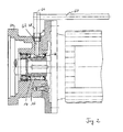
- Fig. 4 shows in an overview sketch the structure of a pitch drive for the locking device described above.
- the pitch drive consists of the engine 10 with its output shaft 12.
- the output shaft 12 of the engine is coupled to a drive shaft 14 of the transmission.
- the drive shaft 14 of the transmission carries the external teeth 16.
- Via a gear 4 with a transmission output shaft 5, a pinion 6 is actuated.
- the pinion 6 meshes in an internally toothed rotary joint 7, through which the rotor blade can be adjusted in position.
- the locking device according to the invention sits between the engine and transmission and engages in the external teeth 16 of the transmission input shaft 14.
Landscapes
- Engineering & Computer Science (AREA)
- Life Sciences & Earth Sciences (AREA)
- Sustainable Development (AREA)
- Sustainable Energy (AREA)
- Chemical & Material Sciences (AREA)
- Combustion & Propulsion (AREA)
- Mechanical Engineering (AREA)
- General Engineering & Computer Science (AREA)
- Physics & Mathematics (AREA)
- Fluid Mechanics (AREA)
- Wind Motors (AREA)
Applications Claiming Priority (1)
| Application Number | Priority Date | Filing Date | Title |
|---|---|---|---|
| DE102009008607A DE102009008607A1 (de) | 2009-02-12 | 2009-02-12 | Vorrichtung zur Arretierung eines Rotorblatts einer Windenergieanlage |
Publications (3)
| Publication Number | Publication Date |
|---|---|
| EP2218908A2 true EP2218908A2 (fr) | 2010-08-18 |
| EP2218908A3 EP2218908A3 (fr) | 2012-07-25 |
| EP2218908B1 EP2218908B1 (fr) | 2014-05-21 |
Family
ID=42034544
Family Applications (1)
| Application Number | Title | Priority Date | Filing Date |
|---|---|---|---|
| EP10001350.7A Active EP2218908B1 (fr) | 2009-02-12 | 2010-02-10 | Eolienne avec un dispositif d'arrêt d'une pale |
Country Status (3)
| Country | Link |
|---|---|
| US (1) | US8702389B2 (fr) |
| EP (1) | EP2218908B1 (fr) |
| DE (1) | DE102009008607A1 (fr) |
Cited By (3)
| Publication number | Priority date | Publication date | Assignee | Title |
|---|---|---|---|---|
| EP2343454A1 (fr) | 2010-01-11 | 2011-07-13 | Ecotecnia Energias Renovables S.L. | Dispositif de blockage de commande auxiliaire d'éolienne |
| CN104179644A (zh) * | 2014-08-22 | 2014-12-03 | 浙江运达风电股份有限公司 | 机械式风轮锁 |
| CN105626395A (zh) * | 2016-02-26 | 2016-06-01 | 大连华锐重工集团股份有限公司 | 一种组合式风电风轮锁盘 |
Families Citing this family (19)
| Publication number | Priority date | Publication date | Assignee | Title |
|---|---|---|---|---|
| ES2611452T3 (es) | 2011-12-06 | 2017-05-09 | Areva Wind Gmbh | Ensamblaje para fijar en posición el ángulo de paso de una pala de rotor de una instalación de energía eólica |
| EP2634416B1 (fr) | 2012-03-01 | 2016-05-18 | ALSTOM Renewables Technologies Wind B.V. | éolienne avec un dispositif de verrouillage |
| US9470208B2 (en) * | 2012-07-05 | 2016-10-18 | General Electric Company | Wind turbine and locking method |
| US20140010656A1 (en) * | 2012-07-05 | 2014-01-09 | Jacob Johannes Nies | Fixation device |
| CN202926533U (zh) | 2012-11-29 | 2013-05-08 | 北京金风科创风电设备有限公司 | 风力发电机及用于风力发电机的叶轮锁定装置 |
| US9816488B2 (en) * | 2013-10-31 | 2017-11-14 | General Electric Company | Rotor turning system and method |
| US20150361955A1 (en) * | 2014-06-11 | 2015-12-17 | Kun Shan University | Blade speed adjustment device by automatic adjustment of the blade elevation angle of a windmill generator |
| DK3098441T3 (da) | 2015-05-27 | 2023-01-30 | Siemens Gamesa Renewable Energy As | Pitchsystemlåseanordning |
| EP3504424B1 (fr) * | 2016-08-26 | 2021-02-24 | Vestas Wind Systems A/S | Système de verrouillage de rotor pour une éolienne |
| WO2018054434A1 (fr) * | 2016-09-21 | 2018-03-29 | Vestas Wind Systems A/S | Ensemble pour éolienne, et procédé de fonctionnement d'un ensemble pour éolienne |
| CN106762397B (zh) * | 2016-12-26 | 2019-06-04 | 江苏金风科技有限公司 | 风力发电机组及其叶轮锁定装置 |
| WO2018124893A1 (fr) | 2016-12-27 | 2018-07-05 | General Electric Company | Ensemble bloc de verrouillage réglable pour roue d'engrenage et procédés d'utilisation associés |
| CN109944754A (zh) * | 2017-12-21 | 2019-06-28 | 天津昊川新能源科技有限公司 | 一种风机叶片维修用锁接架 |
| CN109505733B (zh) * | 2019-01-23 | 2020-11-20 | 上海电气风电集团股份有限公司 | 一种应用于风电台风机组的叶片锁紧装置 |
| DE102019214094A1 (de) * | 2019-09-17 | 2021-03-18 | Zf Friedrichshafen Ag | Fixiermittel für schwere Getriebeteile |
| CN112664392B (zh) | 2019-10-15 | 2025-09-05 | 通用电气可再生能源西班牙有限公司 | 用于在延长的维护期间锁定风力涡轮转子的系统和方法 |
| CN112483326B (zh) * | 2020-11-26 | 2022-01-18 | 三一重能股份有限公司 | 叶轮锁定装置及风力设备 |
| CN115977894B (zh) * | 2023-02-01 | 2023-09-19 | 南通奥里斯特机械有限公司 | 一种高韧性风力发电用风叶部锁定装置 |
| EP4438890A1 (fr) | 2023-03-28 | 2024-10-02 | General Electric Renovables España S.L. | Moyeux de rotor non équilibrés rotatifs et installation de pales de rotor d'éolienne |
Citations (4)
| Publication number | Priority date | Publication date | Assignee | Title |
|---|---|---|---|---|
| DE3110263C2 (de) | 1980-03-17 | 1987-01-22 | United Technologies Corp., Hartford, Conn. | Blatteinstelleinrichtung für eine mit mehreren Blättern versehene Windturbine |
| DE10031472C1 (de) | 2000-06-28 | 2002-04-18 | Tacke Windenergie Gmbh | Vorrichtung zur Arretierung einer von einem Rotor angetriebenen Welle einer Windkraftanlage |
| EP1029176B1 (fr) | 1997-11-04 | 2004-03-03 | WINDTEC Anlagenerrichtungs- und Consulting GmbH | Installation eolienne |
| DE102004017323A1 (de) | 2004-04-06 | 2005-11-03 | Repower Systems Ag | Windenergieanlage |
Family Cites Families (7)
| Publication number | Priority date | Publication date | Assignee | Title |
|---|---|---|---|---|
| US1846488A (en) * | 1930-03-17 | 1932-02-23 | Newel C Jackson | Variable pitch propeller |
| US3003567A (en) * | 1958-08-20 | 1961-10-10 | Gen Motors Corp | Combined mechanical pitch lock and pitch stop assembly |
| US3633951A (en) * | 1970-03-03 | 1972-01-11 | Shur Lok Corp | Rod end coupling with double helix interlock |
| US5554003A (en) * | 1995-05-31 | 1996-09-10 | Hall; Arnold M. | Controllable pitch propeller for propulsor and hydroturbine |
| ES2266833T3 (es) * | 2002-04-26 | 2007-03-01 | General Electric Company | Dispositivo para ajustar las palas del rotor de una turbina de energia eolica. |
| DE202005013329U1 (de) | 2005-08-24 | 2006-02-02 | Weber, Thomas | Arretier- und entsperrbare Verdreheinheit für wälzgelagerte Planetenräder in Windkraft-Planetengetrieben, durch die die dazugehörigen Wälzlager-Innenringe in vollständig montiertem Lager-Zustand und bei zusammengebautem Getriebe von außen verdreht werden können |
| BE1017458A3 (nl) * | 2007-02-06 | 2008-10-07 | Hansen Transmissions Int | Windturbine. |
-
2009
- 2009-02-12 DE DE102009008607A patent/DE102009008607A1/de not_active Withdrawn
- 2009-10-08 US US12/576,046 patent/US8702389B2/en active Active
-
2010
- 2010-02-10 EP EP10001350.7A patent/EP2218908B1/fr active Active
Patent Citations (4)
| Publication number | Priority date | Publication date | Assignee | Title |
|---|---|---|---|---|
| DE3110263C2 (de) | 1980-03-17 | 1987-01-22 | United Technologies Corp., Hartford, Conn. | Blatteinstelleinrichtung für eine mit mehreren Blättern versehene Windturbine |
| EP1029176B1 (fr) | 1997-11-04 | 2004-03-03 | WINDTEC Anlagenerrichtungs- und Consulting GmbH | Installation eolienne |
| DE10031472C1 (de) | 2000-06-28 | 2002-04-18 | Tacke Windenergie Gmbh | Vorrichtung zur Arretierung einer von einem Rotor angetriebenen Welle einer Windkraftanlage |
| DE102004017323A1 (de) | 2004-04-06 | 2005-11-03 | Repower Systems Ag | Windenergieanlage |
Cited By (4)
| Publication number | Priority date | Publication date | Assignee | Title |
|---|---|---|---|---|
| EP2343454A1 (fr) | 2010-01-11 | 2011-07-13 | Ecotecnia Energias Renovables S.L. | Dispositif de blockage de commande auxiliaire d'éolienne |
| CN104179644A (zh) * | 2014-08-22 | 2014-12-03 | 浙江运达风电股份有限公司 | 机械式风轮锁 |
| CN105626395A (zh) * | 2016-02-26 | 2016-06-01 | 大连华锐重工集团股份有限公司 | 一种组合式风电风轮锁盘 |
| CN105626395B (zh) * | 2016-02-26 | 2017-12-29 | 大连华锐重工集团股份有限公司 | 一种组合式风电风轮锁盘 |
Also Published As
| Publication number | Publication date |
|---|---|
| DE102009008607A1 (de) | 2010-08-19 |
| EP2218908A3 (fr) | 2012-07-25 |
| EP2218908B1 (fr) | 2014-05-21 |
| US20100202884A1 (en) | 2010-08-12 |
| US8702389B2 (en) | 2014-04-22 |
Similar Documents
| Publication | Publication Date | Title |
|---|---|---|
| EP2218908B1 (fr) | Eolienne avec un dispositif d'arrêt d'une pale | |
| EP1167754B1 (fr) | Vireur pour le rotor d'une éolienne | |
| EP1167755B1 (fr) | Dispositif de blocage pour le rotor d'une éolienne | |
| EP3350464B1 (fr) | Engrenage planétaire d'une éolienne avec roues planétaires à paliers lisses | |
| EP0354363A2 (fr) | Dispositif de blocage à douille taraudée | |
| EP2154367B1 (fr) | Procédé de montage d'un moyeu d'hélice sur un arbre de rotor d'une éolienne et éolienne | |
| DE202005015774U1 (de) | Stellantrieb zur Einstellung des Anstellwinkels eines Rotorblatts | |
| EP2960490B1 (fr) | Outil rotatif destiné à la torsion d'un composant monté en rotation sur une éolienne | |
| DE202010016197U1 (de) | Spielfrei laufendes Zahnrad | |
| DE102010020355B4 (de) | Arretiervorrichtung für einen Triebstrang einer Windenergieanlage | |
| EP2096737B1 (fr) | Moteur submersible | |
| DE102008019372A1 (de) | Transmissionswelle zur Übertragung eines Drehmomentes und /oder axialer Kräfte | |
| EP1514646A1 (fr) | Appareil pour la pose de rivets-écrous borgnes | |
| DE102016223373B3 (de) | Stellgetriebe | |
| DE102008046166B4 (de) | Werkzeug für Zahnflankenspiel | |
| EP3379077B1 (fr) | Liaison rotative d'une éolienne et pas d'engrenage pour une liaison rotative | |
| WO2020115092A1 (fr) | Rotor pour éolienne et procédé | |
| DE19905126C1 (de) | Sitzverstelleinrichtung für ein Kraftfahrzeug | |
| EP2059694B1 (fr) | Systeme de transmission avec maintien axial | |
| EP1728307A1 (fr) | Entrainement en rotation | |
| DE102016216670B4 (de) | Nockenwellenversteller | |
| EP4370044B1 (fr) | Unité d'alignement et procédé d'assemblage pour un instrument médical | |
| EP2891229B1 (fr) | Motoréducteur | |
| EP1649576B1 (fr) | Element boitier d'un mecanisme d'entrainement et pendant pour une fermeture a baionnette | |
| DE102004048363B4 (de) | Schraube |
Legal Events
| Date | Code | Title | Description |
|---|---|---|---|
| PUAI | Public reference made under article 153(3) epc to a published international application that has entered the european phase |
Free format text: ORIGINAL CODE: 0009012 |
|
| AK | Designated contracting states |
Kind code of ref document: A2 Designated state(s): AT BE BG CH CY CZ DE DK EE ES FI FR GB GR HR HU IE IS IT LI LT LU LV MC MK MT NL NO PL PT RO SE SI SK SM TR |
|
| AX | Request for extension of the european patent |
Extension state: AL BA RS |
|
| PUAL | Search report despatched |
Free format text: ORIGINAL CODE: 0009013 |
|
| AK | Designated contracting states |
Kind code of ref document: A3 Designated state(s): AT BE BG CH CY CZ DE DK EE ES FI FR GB GR HR HU IE IS IT LI LT LU LV MC MK MT NL NO PL PT RO SE SI SK SM TR |
|
| AX | Request for extension of the european patent |
Extension state: AL BA RS |
|
| RIC1 | Information provided on ipc code assigned before grant |
Ipc: F03D 7/02 20060101ALI20120618BHEP Ipc: F03D 1/00 20060101AFI20120618BHEP |
|
| 17P | Request for examination filed |
Effective date: 20130110 |
|
| REG | Reference to a national code |
Ref country code: DE Ref legal event code: R079 Ref document number: 502010007003 Country of ref document: DE Free format text: PREVIOUS MAIN CLASS: F03D0001000000 Ipc: F03D0011000000 |
|
| RIC1 | Information provided on ipc code assigned before grant |
Ipc: F03D 11/00 20060101AFI20130607BHEP |
|
| GRAP | Despatch of communication of intention to grant a patent |
Free format text: ORIGINAL CODE: EPIDOSNIGR1 |
|
| INTG | Intention to grant announced |
Effective date: 20131014 |
|
| RAP1 | Party data changed (applicant data changed or rights of an application transferred) |
Owner name: NORDEX ENERGY GMBH |
|
| GRAP | Despatch of communication of intention to grant a patent |
Free format text: ORIGINAL CODE: EPIDOSNIGR1 |
|
| INTG | Intention to grant announced |
Effective date: 20140128 |
|
| GRAS | Grant fee paid |
Free format text: ORIGINAL CODE: EPIDOSNIGR3 |
|
| GRAA | (expected) grant |
Free format text: ORIGINAL CODE: 0009210 |
|
| AK | Designated contracting states |
Kind code of ref document: B1 Designated state(s): AT BE BG CH CY CZ DE DK EE ES FI FR GB GR HR HU IE IS IT LI LT LU LV MC MK MT NL NO PL PT RO SE SI SK SM TR |
|
| REG | Reference to a national code |
Ref country code: GB Ref legal event code: FG4D Free format text: NOT ENGLISH |
|
| REG | Reference to a national code |
Ref country code: CH Ref legal event code: EP |
|
| REG | Reference to a national code |
Ref country code: AT Ref legal event code: REF Ref document number: 669739 Country of ref document: AT Kind code of ref document: T Effective date: 20140615 |
|
| REG | Reference to a national code |
Ref country code: IE Ref legal event code: FG4D Free format text: LANGUAGE OF EP DOCUMENT: GERMAN |
|
| REG | Reference to a national code |
Ref country code: DE Ref legal event code: R096 Ref document number: 502010007003 Country of ref document: DE Effective date: 20140626 |
|
| REG | Reference to a national code |
Ref country code: SE Ref legal event code: TRGR |
|
| REG | Reference to a national code |
Ref country code: NL Ref legal event code: VDEP Effective date: 20140521 |
|
| REG | Reference to a national code |
Ref country code: LT Ref legal event code: MG4D |
|
| PG25 | Lapsed in a contracting state [announced via postgrant information from national office to epo] |
Ref country code: GR Free format text: LAPSE BECAUSE OF FAILURE TO SUBMIT A TRANSLATION OF THE DESCRIPTION OR TO PAY THE FEE WITHIN THE PRESCRIBED TIME-LIMIT Effective date: 20140822 Ref country code: LT Free format text: LAPSE BECAUSE OF FAILURE TO SUBMIT A TRANSLATION OF THE DESCRIPTION OR TO PAY THE FEE WITHIN THE PRESCRIBED TIME-LIMIT Effective date: 20140521 Ref country code: IS Free format text: LAPSE BECAUSE OF FAILURE TO SUBMIT A TRANSLATION OF THE DESCRIPTION OR TO PAY THE FEE WITHIN THE PRESCRIBED TIME-LIMIT Effective date: 20140921 Ref country code: NO Free format text: LAPSE BECAUSE OF FAILURE TO SUBMIT A TRANSLATION OF THE DESCRIPTION OR TO PAY THE FEE WITHIN THE PRESCRIBED TIME-LIMIT Effective date: 20140821 Ref country code: FI Free format text: LAPSE BECAUSE OF FAILURE TO SUBMIT A TRANSLATION OF THE DESCRIPTION OR TO PAY THE FEE WITHIN THE PRESCRIBED TIME-LIMIT Effective date: 20140521 |
|
| PG25 | Lapsed in a contracting state [announced via postgrant information from national office to epo] |
Ref country code: LV Free format text: LAPSE BECAUSE OF FAILURE TO SUBMIT A TRANSLATION OF THE DESCRIPTION OR TO PAY THE FEE WITHIN THE PRESCRIBED TIME-LIMIT Effective date: 20140521 Ref country code: ES Free format text: LAPSE BECAUSE OF FAILURE TO SUBMIT A TRANSLATION OF THE DESCRIPTION OR TO PAY THE FEE WITHIN THE PRESCRIBED TIME-LIMIT Effective date: 20140521 Ref country code: HR Free format text: LAPSE BECAUSE OF FAILURE TO SUBMIT A TRANSLATION OF THE DESCRIPTION OR TO PAY THE FEE WITHIN THE PRESCRIBED TIME-LIMIT Effective date: 20140521 Ref country code: PL Free format text: LAPSE BECAUSE OF FAILURE TO SUBMIT A TRANSLATION OF THE DESCRIPTION OR TO PAY THE FEE WITHIN THE PRESCRIBED TIME-LIMIT Effective date: 20140521 |
|
| PG25 | Lapsed in a contracting state [announced via postgrant information from national office to epo] |
Ref country code: PT Free format text: LAPSE BECAUSE OF FAILURE TO SUBMIT A TRANSLATION OF THE DESCRIPTION OR TO PAY THE FEE WITHIN THE PRESCRIBED TIME-LIMIT Effective date: 20140922 |
|
| PG25 | Lapsed in a contracting state [announced via postgrant information from national office to epo] |
Ref country code: RO Free format text: LAPSE BECAUSE OF FAILURE TO SUBMIT A TRANSLATION OF THE DESCRIPTION OR TO PAY THE FEE WITHIN THE PRESCRIBED TIME-LIMIT Effective date: 20140521 Ref country code: EE Free format text: LAPSE BECAUSE OF FAILURE TO SUBMIT A TRANSLATION OF THE DESCRIPTION OR TO PAY THE FEE WITHIN THE PRESCRIBED TIME-LIMIT Effective date: 20140521 Ref country code: SK Free format text: LAPSE BECAUSE OF FAILURE TO SUBMIT A TRANSLATION OF THE DESCRIPTION OR TO PAY THE FEE WITHIN THE PRESCRIBED TIME-LIMIT Effective date: 20140521 Ref country code: CZ Free format text: LAPSE BECAUSE OF FAILURE TO SUBMIT A TRANSLATION OF THE DESCRIPTION OR TO PAY THE FEE WITHIN THE PRESCRIBED TIME-LIMIT Effective date: 20140521 Ref country code: DK Free format text: LAPSE BECAUSE OF FAILURE TO SUBMIT A TRANSLATION OF THE DESCRIPTION OR TO PAY THE FEE WITHIN THE PRESCRIBED TIME-LIMIT Effective date: 20140521 |
|
| REG | Reference to a national code |
Ref country code: DE Ref legal event code: R097 Ref document number: 502010007003 Country of ref document: DE |
|
| PG25 | Lapsed in a contracting state [announced via postgrant information from national office to epo] |
Ref country code: NL Free format text: LAPSE BECAUSE OF FAILURE TO SUBMIT A TRANSLATION OF THE DESCRIPTION OR TO PAY THE FEE WITHIN THE PRESCRIBED TIME-LIMIT Effective date: 20140521 |
|
| PLBE | No opposition filed within time limit |
Free format text: ORIGINAL CODE: 0009261 |
|
| STAA | Information on the status of an ep patent application or granted ep patent |
Free format text: STATUS: NO OPPOSITION FILED WITHIN TIME LIMIT |
|
| 26N | No opposition filed |
Effective date: 20150224 |
|
| PG25 | Lapsed in a contracting state [announced via postgrant information from national office to epo] |
Ref country code: IT Free format text: LAPSE BECAUSE OF FAILURE TO SUBMIT A TRANSLATION OF THE DESCRIPTION OR TO PAY THE FEE WITHIN THE PRESCRIBED TIME-LIMIT Effective date: 20140521 |
|
| REG | Reference to a national code |
Ref country code: DE Ref legal event code: R097 Ref document number: 502010007003 Country of ref document: DE Effective date: 20150224 |
|
| PG25 | Lapsed in a contracting state [announced via postgrant information from national office to epo] |
Ref country code: BE Free format text: LAPSE BECAUSE OF NON-PAYMENT OF DUE FEES Effective date: 20150228 |
|
| PG25 | Lapsed in a contracting state [announced via postgrant information from national office to epo] |
Ref country code: SI Free format text: LAPSE BECAUSE OF FAILURE TO SUBMIT A TRANSLATION OF THE DESCRIPTION OR TO PAY THE FEE WITHIN THE PRESCRIBED TIME-LIMIT Effective date: 20140521 |
|
| PG25 | Lapsed in a contracting state [announced via postgrant information from national office to epo] |
Ref country code: LU Free format text: LAPSE BECAUSE OF FAILURE TO SUBMIT A TRANSLATION OF THE DESCRIPTION OR TO PAY THE FEE WITHIN THE PRESCRIBED TIME-LIMIT Effective date: 20150210 |
|
| REG | Reference to a national code |
Ref country code: CH Ref legal event code: PL |
|
| PG25 | Lapsed in a contracting state [announced via postgrant information from national office to epo] |
Ref country code: MC Free format text: LAPSE BECAUSE OF FAILURE TO SUBMIT A TRANSLATION OF THE DESCRIPTION OR TO PAY THE FEE WITHIN THE PRESCRIBED TIME-LIMIT Effective date: 20140521 Ref country code: LI Free format text: LAPSE BECAUSE OF NON-PAYMENT OF DUE FEES Effective date: 20150228 Ref country code: CH Free format text: LAPSE BECAUSE OF NON-PAYMENT OF DUE FEES Effective date: 20150228 |
|
| REG | Reference to a national code |
Ref country code: IE Ref legal event code: MM4A |
|
| PG25 | Lapsed in a contracting state [announced via postgrant information from national office to epo] |
Ref country code: IE Free format text: LAPSE BECAUSE OF NON-PAYMENT OF DUE FEES Effective date: 20150210 |
|
| REG | Reference to a national code |
Ref country code: FR Ref legal event code: PLFP Year of fee payment: 7 |
|
| REG | Reference to a national code |
Ref country code: AT Ref legal event code: MM01 Ref document number: 669739 Country of ref document: AT Kind code of ref document: T Effective date: 20150210 |
|
| PG25 | Lapsed in a contracting state [announced via postgrant information from national office to epo] |
Ref country code: AT Free format text: LAPSE BECAUSE OF NON-PAYMENT OF DUE FEES Effective date: 20150210 |
|
| PG25 | Lapsed in a contracting state [announced via postgrant information from national office to epo] |
Ref country code: MT Free format text: LAPSE BECAUSE OF FAILURE TO SUBMIT A TRANSLATION OF THE DESCRIPTION OR TO PAY THE FEE WITHIN THE PRESCRIBED TIME-LIMIT Effective date: 20140521 |
|
| REG | Reference to a national code |
Ref country code: FR Ref legal event code: PLFP Year of fee payment: 8 |
|
| PG25 | Lapsed in a contracting state [announced via postgrant information from national office to epo] |
Ref country code: SM Free format text: LAPSE BECAUSE OF FAILURE TO SUBMIT A TRANSLATION OF THE DESCRIPTION OR TO PAY THE FEE WITHIN THE PRESCRIBED TIME-LIMIT Effective date: 20140521 Ref country code: HU Free format text: LAPSE BECAUSE OF FAILURE TO SUBMIT A TRANSLATION OF THE DESCRIPTION OR TO PAY THE FEE WITHIN THE PRESCRIBED TIME-LIMIT; INVALID AB INITIO Effective date: 20100210 Ref country code: BG Free format text: LAPSE BECAUSE OF FAILURE TO SUBMIT A TRANSLATION OF THE DESCRIPTION OR TO PAY THE FEE WITHIN THE PRESCRIBED TIME-LIMIT Effective date: 20140521 |
|
| PG25 | Lapsed in a contracting state [announced via postgrant information from national office to epo] |
Ref country code: CY Free format text: LAPSE BECAUSE OF FAILURE TO SUBMIT A TRANSLATION OF THE DESCRIPTION OR TO PAY THE FEE WITHIN THE PRESCRIBED TIME-LIMIT Effective date: 20140521 |
|
| PG25 | Lapsed in a contracting state [announced via postgrant information from national office to epo] |
Ref country code: TR Free format text: LAPSE BECAUSE OF FAILURE TO SUBMIT A TRANSLATION OF THE DESCRIPTION OR TO PAY THE FEE WITHIN THE PRESCRIBED TIME-LIMIT Effective date: 20140521 |
|
| REG | Reference to a national code |
Ref country code: FR Ref legal event code: PLFP Year of fee payment: 9 |
|
| PG25 | Lapsed in a contracting state [announced via postgrant information from national office to epo] |
Ref country code: MK Free format text: LAPSE BECAUSE OF FAILURE TO SUBMIT A TRANSLATION OF THE DESCRIPTION OR TO PAY THE FEE WITHIN THE PRESCRIBED TIME-LIMIT Effective date: 20140521 |
|
| PGFP | Annual fee paid to national office [announced via postgrant information from national office to epo] |
Ref country code: SE Payment date: 20190221 Year of fee payment: 10 |
|
| REG | Reference to a national code |
Ref country code: SE Ref legal event code: EUG |
|
| PG25 | Lapsed in a contracting state [announced via postgrant information from national office to epo] |
Ref country code: SE Free format text: LAPSE BECAUSE OF NON-PAYMENT OF DUE FEES Effective date: 20200211 |
|
| REG | Reference to a national code |
Ref country code: DE Ref legal event code: R082 Ref document number: 502010007003 Country of ref document: DE Representative=s name: HAUCK PATENTANWALTSPARTNERSCHAFT MBB, DE Ref country code: DE Ref legal event code: R081 Ref document number: 502010007003 Country of ref document: DE Owner name: NORDEX ENERGY SE & CO. KG, DE Free format text: FORMER OWNER: NORDEX ENERGY GMBH, 22419 HAMBURG, DE |
|
| P01 | Opt-out of the competence of the unified patent court (upc) registered |
Effective date: 20230602 |
|
| PGFP | Annual fee paid to national office [announced via postgrant information from national office to epo] |
Ref country code: GB Payment date: 20260219 Year of fee payment: 17 |
|
| PGFP | Annual fee paid to national office [announced via postgrant information from national office to epo] |
Ref country code: DE Payment date: 20260217 Year of fee payment: 17 |
|
| PGFP | Annual fee paid to national office [announced via postgrant information from national office to epo] |
Ref country code: FR Payment date: 20260219 Year of fee payment: 17 |