EP2219042A1 - Fehlerfeststellungsverfahren zur Feststellung von Leckwegen zwischen Stromquellen und Fahrgestell - Google Patents
Fehlerfeststellungsverfahren zur Feststellung von Leckwegen zwischen Stromquellen und Fahrgestell Download PDFInfo
- Publication number
- EP2219042A1 EP2219042A1 EP10001540A EP10001540A EP2219042A1 EP 2219042 A1 EP2219042 A1 EP 2219042A1 EP 10001540 A EP10001540 A EP 10001540A EP 10001540 A EP10001540 A EP 10001540A EP 2219042 A1 EP2219042 A1 EP 2219042A1
- Authority
- EP
- European Patent Office
- Prior art keywords
- current
- controller
- switch
- direct current
- chassis
- Prior art date
- Legal status (The legal status is an assumption and is not a legal conclusion. Google has not performed a legal analysis and makes no representation as to the accuracy of the status listed.)
- Granted
Links
Images


Classifications
-
- B—PERFORMING OPERATIONS; TRANSPORTING
- B60—VEHICLES IN GENERAL
- B60L—PROPULSION OF ELECTRICALLY-PROPELLED VEHICLES; SUPPLYING ELECTRIC POWER FOR AUXILIARY EQUIPMENT OF ELECTRICALLY-PROPELLED VEHICLES; ELECTRODYNAMIC BRAKE SYSTEMS FOR VEHICLES IN GENERAL; MAGNETIC SUSPENSION OR LEVITATION FOR VEHICLES; MONITORING OPERATING VARIABLES OF ELECTRICALLY-PROPELLED VEHICLES; ELECTRIC SAFETY DEVICES FOR ELECTRICALLY-PROPELLED VEHICLES
- B60L3/00—Electric devices on electrically-propelled vehicles for safety purposes; Monitoring operating variables, e.g. speed, deceleration or energy consumption
- B60L3/0023—Detecting, eliminating, remedying or compensating for drive train abnormalities, e.g. failures within the drive train
-
- B—PERFORMING OPERATIONS; TRANSPORTING
- B60—VEHICLES IN GENERAL
- B60L—PROPULSION OF ELECTRICALLY-PROPELLED VEHICLES; SUPPLYING ELECTRIC POWER FOR AUXILIARY EQUIPMENT OF ELECTRICALLY-PROPELLED VEHICLES; ELECTRODYNAMIC BRAKE SYSTEMS FOR VEHICLES IN GENERAL; MAGNETIC SUSPENSION OR LEVITATION FOR VEHICLES; MONITORING OPERATING VARIABLES OF ELECTRICALLY-PROPELLED VEHICLES; ELECTRIC SAFETY DEVICES FOR ELECTRICALLY-PROPELLED VEHICLES
- B60L3/00—Electric devices on electrically-propelled vehicles for safety purposes; Monitoring operating variables, e.g. speed, deceleration or energy consumption
- B60L3/0023—Detecting, eliminating, remedying or compensating for drive train abnormalities, e.g. failures within the drive train
- B60L3/0069—Detecting, eliminating, remedying or compensating for drive train abnormalities, e.g. failures within the drive train relating to the isolation, e.g. ground fault or leak current
-
- G—PHYSICS
- G01—MEASURING; TESTING
- G01R—MEASURING ELECTRIC VARIABLES; MEASURING MAGNETIC VARIABLES
- G01R31/00—Arrangements for testing electric properties; Arrangements for locating electric faults; Arrangements for electrical testing characterised by what is being tested not provided for elsewhere
- G01R31/50—Testing of electric apparatus, lines, cables or components for short-circuits, continuity, leakage current or incorrect line connections
- G01R31/52—Testing for short-circuits, leakage current or ground faults
-
- G—PHYSICS
- G01—MEASURING; TESTING
- G01R—MEASURING ELECTRIC VARIABLES; MEASURING MAGNETIC VARIABLES
- G01R31/00—Arrangements for testing electric properties; Arrangements for locating electric faults; Arrangements for electrical testing characterised by what is being tested not provided for elsewhere
- G01R31/005—Testing of electric installations on transport means
- G01R31/006—Testing of electric installations on transport means on road vehicles, e.g. automobiles or trucks
- G01R31/007—Testing of electric installations on transport means on road vehicles, e.g. automobiles or trucks using microprocessors or computers
Definitions
- the following disclosure relates to electrical fault detection systems and methods for high voltage DC systems.
- Plug-in and hybrid vehicles typically use a high voltage DC drive powered with large batteries or battery packs. Voltages present in these systems may range from 100 to 1000 or greater. Consequently, the use of such systems can present a danger if the high voltage system is not effectively isolated from the vehicle chassis.
- the threshold voltage where DC becomes dangerous can be as low as 55 to 60 volts and contact with a high voltage DC source can cause serious injuries. Contact with direct current tends to cause continuous muscular contractions that make the victim hold on to a live conductor, increasing the risk of bums and other injuries.
- Current leakage from the high voltage system to the chassis may result from frayed wires contacting chassis components and component failure. Corrosion and/or infiltration of salt, dirt and other debris may provide a current path. Consequently it is important to identify potentially dangerous faults.
- One presently proposed fault detectors utilizes a capacitively coupled signal injected into an isolated ground.
- large amounts of parasitic and inherent capacitance in electrically powered vehicles tend to make such devices too "noisy" for reliable use of a capacitively coupled signal for fault detection.
- Another proposed approach is the use of a wheatstone bridge.
- a short across the detection nodes of a wheatstone bridge may be undetectable.
- an apparatus for monitoring a direct current system for ground faults in a device having inherent capacitance between the direct current system and a chassis ground includes a fault detection module connected between the chassis ground and a first switch and a second switch.
- the first switch is also connected between a positive node of the direct current system and the fault detection module.
- the second switch is connected between a negative node of the direct current system and the fault detection module.
- a switch driver is provided to sequentially open and close the first and second switches such that the inherent capacitance is charged and discharged.
- the fault detection module includes a controller for controlling the switch driver and a current sensor.
- the current sensor senses a first current when the first switch is closed and a second current when the second switch is closed. The current sensor then transmits a signal to the controller indicating an amperage or measurement of the first and second currents.
- a data interface connected to the controller outputs a signal in response to the amperage or measurement of the first and second currents.
- the current sensor may include a programmable gain amplifier and an analog to digital signal converter wherein the programmable gain amplifier transmits a signal to the analog to digital signal converter and the analog to digital signal converter transmits a signal to the controller.
- a first resistor is connected in series between the positive node of the direct current system and the first switch.
- a second resistor is connected between the negative node of the direct current system and the second switch.
- the resistances of the first and second resistors are substantially equal.
- the resistances of the first and second resistors is typically high, on the order of a mega ohm.
- the apparatus may include a non-volatile memory connected to the controller, with preprogrammed instructions that are utilized by the controller for detecting a fault based on changes in the first and second currents.
- the non-volatile memory may also include or be programmed to include instructions, utilized by the controller, for determining a parasitic resistance of the direct current system signal in response to changes in the first and second currents as well as instructions, utilized by the controller, for determining a leakage current of the direct current system signal based on the first and second currents.
- the fault detection module is also connected to a first switch and a second switch, which are in turn connected to positive and negative nodes of the direct current power system respectively.
- the fault detection module includes a switch output driver control that sequentially or in an alternating manner opens and closes the first and second switches to charge and discharge the inherent capacitance at predetermined intervals.
- a current sensor senses a first current when the first switch is closed while the inherent capacitance is charged and senses a second current when the second switch is closed while the inherent capacitance is discharged.
- a digital controller which may include a signal processor, utilizes preprogrammed instructions stored in a non-volatile memory to determine if a ground fault condition exists between the direct current power system and the vehicle's chassis.
- a data interface connected to the digital controller sends a signal, indicative of whether a fault condition is detected, to an on board computer or other controller or processor of the vehicle.
- a method of detecting a ground fault condition in a direct current power system of an electric vehicle or hybrid-electric vehicle includes sequentially opening and closing a first switch connected between a positive node of the direct current power system and a chassis ground of the electric vehicle and a second switch connected between a negative node the of direct current power system and the chassis ground of the electric vehicle.
- a first switch connected between a positive node of the direct current power system and a chassis ground of the electric vehicle
- a second switch connected between a negative node the of direct current power system and the chassis ground of the electric vehicle.
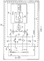
- Fig. 1 illustrates a schematic representation of a high-voltage DC electrical system employing a fault detection system according to the disclosure
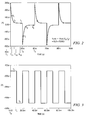
- Fig. 2 is a graph illustrating the simulated operation of the fault detection system
- Fig. 3 is a graph illustrating the simulated operation of the fault detection system of Fig. 1 in the case of a fault
- Fig. 4 is a graph representing the simulated operation of the fault detection system of Fig. 1 in a case of a second fault
- Fig. 5 is a graph further illustrating the simulated operation of the fault detection system of Fig. 1 ;
- Fig. 6 is a block diagram illustrating one configuration of the fault detection module of Fig. 1 .
- Fig. 1 is a schematic representation of a high-voltage DC electrical system employing an exemplary fault detection system 100.
- system 100 may be employed in an electrically-powered vehicle 102, such as a golf cart or automobile, driven by an electrical motor 104 and powered with a battery or battery pack 106.
- System 100 may also be employed in a gasoline-electric hybrid or other type of hybrid electric device or machine. Such systems typically operate at relatively high voltages, e.g., 100 - 1000 volts or higher.
- a detection module 108 which will be described in greater detail below, is connected to the positive terminal of battery 106 through a first switch 110 and a first resistor 112.
- Detection module 108 is also connected to the negative terminal of battery 106 through a second switch 116 and a second resistor 118.
- the first switch 110 and the second switch 116 may be combined as a single pole and double throw style switch or relay 113 as optionally shown.
- switches 110 and 116 are sequentially opened and closed under the control of fault detection module 108.
- First and second switches 110, 116 are high-voltage, solid-state switches, for example, optically-coupled relays.
- First and second resistors 112, 118 are large-value resistors, typically on the order of 1 mega ohm or greater. Preferably, the resistance values of resistors 112, 118 are equal or substantially equal.
- the system 100 includes an over-voltage protection device that may include zener diodes 120. Other devices may be used to provide over-voltage protection for this system. As illustrated zener diodes 120 are connected between the chassis ground 122 and the high voltage system and have a breakdown voltage slightly greater than the potential across the direct current supply system, battery or battery pack 106.
- parasitic resistance in the system is represented by resistor 124.
- the value of resistance 124 is very large, on the order of mega ohms.
- Capacitor 126 represents the inherent capacitance in the system existing between the battery section 106 and the vehicle chassis ground 122. In the case of an electrically-powered vehicle, an inherent capacitance 126 is typically large due to the number and size of metal chassis components positioned near or adjacent to metal portions of the high-voltage system.
- Fig. 2 is a graph illustrating the simulated operation of exemplary fault detection system 100.
- the value of resistor 112 is assumed to be 1 mega ohm
- the value of inherent capacitance 126 is assumed to be 1 nanofarad
- the value of parasitic resistance 124 is assumed to be 10 mega ohms. This represents an ideal condition where there is little or no current leakage from the high voltage system to the chassis ground.
- switch 110 is closed at time To, current flows through resistor 112 and switch 110 until the inherent capacitance 126 is charged.
- the value of I 1 declines, approaching zero, reflecting the large value of resistor 112.
- switch 110 is opened and switch 116 is closed.
- Inherent capacitance 126 is discharged through resistor 118 and switch 116 resulting in current flow I 2 . As illustrated, as capacitance 126 is discharged, the value of I 2 approaches zero. As will be appreciated, Fig. 2 represents a system having a very high parasitic resistance and, consequently, a low leakage current designated as I lk in Fig. 1 .
- Fig. 3 is a graph illustrating the simulated operation of the exemplary fault detection system 100 of Fig. 1 in the case of a fault.
- a 300 volt battery system 106 is assumed with the values of resistors 112 and 118 set at 1 mega ohms and with the value of capacitance 126 being 1 nanofarad.
- a leakage current of 10 milliamps (I lk ) is also assumed.
- switch 110 is closed. Current I 1 flows through the resistor 112 and switch 110. However, in this example the current flow I 1 does not decline due to leakage current flowing through parasitic resistance 124.
- switch 110 is opened and switch 116 is closed. Current I 2 flows through resistor 118 and switch 116. Again, the value of I 2 does not decline due to leakage I lk across parasitic resistance 124.
- Fig. 4 is a graph representing the simulated operation of the fault detection system of Fig. 1 in a case where the value of parasitic resistance 124 is assumed to be 300 kilohms. Again, the values of resistors 112 and 118 are assumed to be 1 mega ohm and the value of inherent capacitance 126 is assumed to be 1 nanofarad.
- switch 110 is closed and current flows through resistor 112 and the switch. As illustrated, the value of current I 1 declines rapidly, however, the value of I 1 does not approach zero due to leakage across parasitic resistance 124.
- Fig. 5 is a graph illustrating the simulated operation of the fault detection system of Fig. 1 wherein resistor 112 has failed open.
- a 300 volt battery system 106 is assumed wherein the value of resistor 118 is 1 mega ohm and the value of parasitic resistance 124 is 300 kilohms with the value of inherent capacitance 126 being 1 nanofarad.
- switch 110 is closed. However, because resistor 112 has failed open, no I 1 current flows through resistor 112. The lack of an I 1 current is indicative and can be measured as a failed open resistor 112.
- switch 116 is closed and switch 110 is opened.
- current I 2 flows through switch 116 and resistor 118 peaking and then declining to a level reflecting the relatively low value of parasitic resistance 124.
- switch 116 is opened and switch 110 is closed.
- the value of I 1 goes to zero because of the failure of resistor 112.
- the circled portion 200 identifies a further detectable and measurable indication that resistor 112 is failed open.
- the further indication of an open resistor 112 is seen, for example, at time T4 in the circled portion 200, wherein the overshoot 202 normally seen due to the occurrence of a capacitor/resistor charge or discharge, is not present.
- each leading or overshoot portion 200, 202 of the I 1 , I 2 wave form can also be monitored or compared by the controller (as discussed below) in order to determine if there is a system resistor failure.
- a failure of resistor 118 can also be monitored.
- multiple current measurements taken at different locations of the I 1 , I 2 current wave form can be used to determine whether a ground fault occurs or whether the ground fault detection circuit or detection system has failed.
- Fig. 6 is a block diagram illustrating an exemplary configuration of fault detection module 108 of Fig. 1 .
- module 108 includes a digital controller or a microprocessor 600 and an associated non-volatile memory 602.
- Non-volatile memory 602 may be programmed or provided with instructions for storage. The stored instructions are utilized by the operating module 108 for specific applications.
- non-volatile memory 602 may be programmed with instructions dictating the frequency at which switches 110 and 116 are sequentially cycled, the frequency at which currents I 1 and I 2 are measured or sampled and threshold values for indicating a fault.
- microprocessor 600 controls the operation of switches 110 and 116 via a switch output driver control 604.
- the values of I 1 and I 2 are measured using a current sensor circuit 605 that may include a transimpedance programmable gain amplifier or a programmable/adjustable current sensor 606.
- the transimpedance programmable amplifier 606 essentially represents a current measurement of an input (IN) as a voltage output (V OUT ).
- other devices or circuits that provide an output signal that represents a measurement of a current flow or that performs essentially the same function may be used.
- values of I 1 and I 2 may be determined or measured at predetermined intervals. For example, the value of I 1 may be sampled one, two, three or more times between T 0 and T 2 . Other sampling frequencies may be used.
- the output of programmable gain amplifier 606 is received by an analog to digital converter 608, which converts the voltage output signal to a digital output.
- the digital output is sampled at predetermined intervals under the control of microprocessor 600 and the samples are stored in storage registers 610. In some embodiments, selected stored values may be averaged in order to smooth the current measurements over a predetermined period of time and/or over a predetermined number of stored value samples.
- the digital output of the current sensor circuit 605 or of the analog to digital converter 608 is provided directly, substantially directly or indirectly to the controller 600.
- Analog to digital converter 608 may be supplied with a reference voltage from one of an internal reference voltage circuit 614 or from an external reference voltage 612.
- Module 108 may be powered with the output of a voltage regulator circuit 616, which may be integral to the module 108 or may be a separate external device.
- Module 108 also includes a data or communication interface 618 allowing microprocessor 600 to communicate with an external device.
- Various standard communication interfaces can be employed as the communications interface 618, including, but not limited to, I 2 C, CAN, SAA, one-wire or other communication interfaces including custom communication interfaces as well as analog signal interfaces.
- communications interface 618 may transmit a signal indicative of whether a fault is detected to a controller or computer system of the electrical vehicle.
- microprocessor 600 may transmit a signal indicating the presence of a fault through interface 618 to an electric vehicle's computer or control system. In this variation, a number of actions may be taken.
- an audible or visual alarm may be sounded or a relay may be opened when the vehicle is turned off and placed in "park” to disable the vehicle's electrical system.
- the output of the signal from microprocessor 600 through communications interface 618 is utilized for diagnostic purposes with a test device.
- the value of parasitic resistance 124 may be determined as follows.
- I 1 V ⁇ 1 - VR / RS 1 + R lk
- RS 1 is the resistance of first resistor 112
- R lk is the value of parasitic resistance 124
- V 1 and VR are the indicated voltages in Figure 1 .
- I 2 V ⁇ 2 - VR / RS 2 + R lk
- RS 2 is the resistance of the second resistor 116.
- I 1 and I 2 are measured using the detection module 108 and VBATT and RS 2 are known quantities, the foregoing equation can be solved using the digital controller 600 and instruction from the non-volatile memory 602, for R lk .
- system 100 is illustrated as being connected directly to the terminals of battery pack 106, in other versions it may be connected across different nodes of the high voltage system.
- system 100 may be incorporated into high voltage battery packs for vehicles, utilized in battery powered backup power systems, cordless power tools or equipment and similar devices.
- the fault detection module 108 may be incorporated into the direct current power supply side or onto the chassis side of the vehicle, device, or machine.
- Another embodiment of the invention may comprise a hand or user held high voltage ground fault tester that incorporates the module 108 and the switches 110 and 116, while having a three pronged lead connected thereto.
- One of the three leads could be made to contact a chassis or device ground
- the second lead may incorporate a resistor RS 1 112 and contact a high side of a high voltage DC power source
- the third lead may incorporate a resistor RS2 118 and contact a low or ground side of the high voltage DC power source.
Landscapes
- Engineering & Computer Science (AREA)
- Life Sciences & Earth Sciences (AREA)
- Sustainable Development (AREA)
- Sustainable Energy (AREA)
- Power Engineering (AREA)
- Transportation (AREA)
- Mechanical Engineering (AREA)
- Physics & Mathematics (AREA)
- General Physics & Mathematics (AREA)
- Testing Of Short-Circuits, Discontinuities, Leakage, Or Incorrect Line Connections (AREA)
- Emergency Protection Circuit Devices (AREA)
- Electric Propulsion And Braking For Vehicles (AREA)
Applications Claiming Priority (2)
| Application Number | Priority Date | Filing Date | Title |
|---|---|---|---|
| US15290509P | 2009-02-16 | 2009-02-16 | |
| US12/403,235 US8040139B2 (en) | 2009-02-16 | 2009-03-12 | Fault detection method for detecting leakage paths between power sources and chassis |
Publications (2)
| Publication Number | Publication Date |
|---|---|
| EP2219042A1 true EP2219042A1 (de) | 2010-08-18 |
| EP2219042B1 EP2219042B1 (de) | 2019-04-10 |
Family
ID=42145899
Family Applications (1)
| Application Number | Title | Priority Date | Filing Date |
|---|---|---|---|
| EP10001540.3A Active EP2219042B1 (de) | 2009-02-16 | 2010-02-15 | Fehlerfeststellungsverfahren zur Feststellung von Leckwegen zwischen Stromquellen und Fahrgestell |
Country Status (3)
| Country | Link |
|---|---|
| US (1) | US8040139B2 (de) |
| EP (1) | EP2219042B1 (de) |
| CN (1) | CN101846711B (de) |
Cited By (2)
| Publication number | Priority date | Publication date | Assignee | Title |
|---|---|---|---|---|
| CN112285413A (zh) * | 2020-10-15 | 2021-01-29 | 中国第一汽车股份有限公司 | 电流值确定方法、装置、控制器、介质及电池管理系统 |
| US11374395B2 (en) * | 2017-06-29 | 2022-06-28 | Huawei Technologies Co., Ltd. | Remote power unit, direct current power system and direct current power system fault detection method |
Families Citing this family (51)
| Publication number | Priority date | Publication date | Assignee | Title |
|---|---|---|---|---|
| JP5334500B2 (ja) * | 2008-08-29 | 2013-11-06 | 三洋電機株式会社 | 車両用の電源装置 |
| US8427167B2 (en) | 2009-04-08 | 2013-04-23 | Analog Devices, Inc. | Architecture and method to determine leakage impedance and leakage voltage node |
| US9523730B2 (en) | 2009-04-08 | 2016-12-20 | Analog Devices, Inc. | Architecture and method to determine leakage impedance and leakage voltage node |
| US20110049977A1 (en) * | 2009-09-01 | 2011-03-03 | Boston-Power, Inc. | Safety and performance optimized controls for large scale electric vehicle battery systems |
| US8618809B2 (en) * | 2010-06-15 | 2013-12-31 | Deere & Company | Electrical isolation detection with enhanced dynamic range |
| FR2966652B1 (fr) * | 2010-10-21 | 2012-11-02 | Renault Sa | Dispositif et procede d'estimation d'un courant de toucher et de protection d'un appareil electrique contre de tels courants de toucher |
| US8766490B2 (en) | 2011-03-25 | 2014-07-01 | Enerdel, Inc. | System and method for monitoring operation of switch elements |
| DE102011089145A1 (de) * | 2011-12-20 | 2013-06-20 | Robert Bosch Gmbh | Schutzvorrichtung, Verfahren und Energieversorgungssystem |
| US9341665B2 (en) * | 2012-04-18 | 2016-05-17 | Lear Corporation | Method and apparatus for high voltage isolation monitor for a vehicle |
| US9046559B2 (en) * | 2012-05-09 | 2015-06-02 | Curtis Instruments, Inc. | Isolation monitor |
| US9162579B2 (en) * | 2012-06-29 | 2015-10-20 | Lg Chem, Ltd. | Driver circuit for an electric vehicle and a diagnostic method for determining when a first voltage driver is shorted to a low voltage and a second voltage driver is shorted to a high voltage |
| US9050893B2 (en) | 2012-06-29 | 2015-06-09 | Lg Chem, Ltd. | Driver circuit for an electric vehicle and a diagnostic method for determining when a first voltage driver is shorted to a high voltage and a second voltage driver has a low electrical current flowing therethrough |
| US8861161B2 (en) * | 2012-06-29 | 2014-10-14 | Lg Chem, Ltd. | Driver circuit for an electric vehicle and a diagnostic method for determining when first and second voltage drivers are shorted to a high voltage |
| US8994210B2 (en) * | 2012-07-02 | 2015-03-31 | Lg Chem, Ltd. | Driver circuit for an electric vehicle and a diagnostic method for determining when an electrical short circuit to a ground voltage is present between a contactor coil and a voltage driver |
| US9024468B2 (en) | 2012-07-02 | 2015-05-05 | Lg Chem, Ltd. | Driver circuit for an electric vehicle and a diagnostic method for determining when a voltage driver is shorted to a ground voltage |
| DE102012013405A1 (de) * | 2012-07-05 | 2014-01-09 | Audi Ag | Diagnoseeinrichtung zur Überprüfung einer Steuersignalleitung |
| DE102012015911B3 (de) * | 2012-08-10 | 2013-10-24 | Audi Ag | Diagnoseeinrichtung zur Überprüfung einer Steuersignalleitung |
| US9120382B2 (en) * | 2012-08-27 | 2015-09-01 | Ford Global Technologies, Llc | Traction battery discharge control |
| US9234931B2 (en) * | 2013-03-08 | 2016-01-12 | Caterpillar Inc. | Fault detection system with leakage current detection |
| JP6247154B2 (ja) * | 2014-05-26 | 2017-12-13 | カルソニックカンセイ株式会社 | 車両用地絡検出装置 |
| CN105510765B (zh) * | 2014-09-24 | 2020-01-07 | 中车大连电力牵引研发中心有限公司 | 接地故障诊断装置 |
| US9705306B2 (en) | 2014-10-23 | 2017-07-11 | Honeywell International Inc. | Non-isolated power supply output chassis ground fault detection and protection system |
| US9630520B2 (en) * | 2015-01-13 | 2017-04-25 | Ford Global Technologies, Llc | Circuit and method for battery leakage detection |
| US9772392B2 (en) | 2015-02-26 | 2017-09-26 | Lear Corporation | Apparatus and method for diagnosing hardware in an insulation resistance monitoring system for a vehicle |
| US9859085B2 (en) | 2015-09-23 | 2018-01-02 | Hamilton Sundstrand Corporation | Fault protection devices and methods for power systems |
| JP6512072B2 (ja) * | 2015-11-10 | 2019-05-15 | 株式会社デンソー | 故障検査システム |
| US10020676B2 (en) * | 2016-03-28 | 2018-07-10 | Nxp B.V. | Watchdog circuit |
| KR102145524B1 (ko) | 2016-06-22 | 2020-08-18 | 주식회사 엘지화학 | 전기 자동차용 구동 회로 및 그 제어 방법 |
| JP6708046B2 (ja) * | 2016-08-05 | 2020-06-10 | 株式会社デンソー | 漏電判定装置 |
| JP6515895B2 (ja) * | 2016-08-30 | 2019-05-22 | トヨタ自動車株式会社 | 充電システムおよび電動車両 |
| US10393789B2 (en) * | 2016-11-04 | 2019-08-27 | Siemens Mobility, Inc. | Ground fault tester |
| US10203363B2 (en) | 2016-12-14 | 2019-02-12 | General Electric Company | DC leakage current detector and method of operation thereof for leakage current detection in DC power circuits |
| US10168372B2 (en) | 2016-12-14 | 2019-01-01 | General Electric Company | System and method for leakage current and fault location detection in electric vehicle DC power circuits |
| DE102017215006A1 (de) * | 2017-08-28 | 2019-02-28 | Siemens Aktiengesellschaft | Erkennen eines Fehlers in einem Gleichstromübertragungssystem |
| US10513185B2 (en) | 2017-12-20 | 2019-12-24 | Ford Global Technologies, Llc | Electrified vehicle ground fault monitoring system |
| JP6725577B2 (ja) * | 2018-04-09 | 2020-07-22 | 矢崎総業株式会社 | 地絡検出装置 |
| DE202018104044U1 (de) * | 2018-07-13 | 2019-10-15 | Wago Verwaltungsgesellschaft Mbh | Erdleiter-Überwachung |
| US10787079B2 (en) * | 2018-09-27 | 2020-09-29 | Ford Global Technologies, Llc | Vehicle ground path impedance difference detection |
| US10948530B2 (en) * | 2018-10-29 | 2021-03-16 | Lear Corporation | Apparatus and method for asymmetrical isolation monitor failure detection |
| CN109447187B (zh) * | 2018-12-25 | 2021-06-15 | 中南大学 | 电机故障诊断方法及系统 |
| CA3145860A1 (en) * | 2019-07-03 | 2021-01-07 | Earth Networks, Inc. | Antenna for use with lightning detection sensor |
| WO2021040900A1 (en) | 2019-08-23 | 2021-03-04 | Stafl Systems, LLC | Location-determinant fault monitoring for battery management system |
| DE102019124213A1 (de) * | 2019-09-10 | 2021-03-11 | Audi Ag | Galvanisch verbundenes AC-Ladegerät mit Überwachungs- und Diagnosesystem |
| WO2021085885A1 (ko) * | 2019-10-29 | 2021-05-06 | 주식회사 엘지화학 | 누전 검출 장치, 누전 검출 방법 및 전기 차량 |
| CN111487558B (zh) * | 2020-04-02 | 2022-09-13 | 中车青岛四方机车车辆股份有限公司 | 列车高压系统故障定位装置与方法 |
| CN111487504B (zh) * | 2020-04-29 | 2022-05-13 | 南京国臣直流配电科技有限公司 | 一种直流系统交流窜入直流故障快速保护方法 |
| US11689012B2 (en) | 2020-04-29 | 2023-06-27 | Maxim Integrated Products, Inc. | Systems and methods to cable shield fault detection and protection |
| US12041396B2 (en) * | 2020-07-16 | 2024-07-16 | R9 Labs, Llc | Systems and methods for processing data proximate to the point of collection |
| US11506696B2 (en) * | 2020-10-15 | 2022-11-22 | Western Digital Technologies, Inc. | Hold-up capacitance health measurement with current leakage detection |
| KR102769382B1 (ko) * | 2022-10-26 | 2025-02-14 | 에스케이브로드밴드주식회사 | 누수감지장치 및 누수 감지 방법 |
| US12194883B2 (en) * | 2023-02-01 | 2025-01-14 | Ford Global Technologies, Llc | Vehicle electric power take-off |
Citations (2)
| Publication number | Priority date | Publication date | Assignee | Title |
|---|---|---|---|---|
| US5561380A (en) * | 1995-05-08 | 1996-10-01 | Chrysler Corporation | Fault detection system for electric automobile traction system having floating ground |
| US7075311B1 (en) * | 2005-04-28 | 2006-07-11 | Yazaki Corporation | Insulation detecting device for non-grounded power source |
Family Cites Families (48)
| Publication number | Priority date | Publication date | Assignee | Title |
|---|---|---|---|---|
| CA938674A (en) * | 1970-12-22 | 1973-12-18 | K. G. Stelter Manfred | Ground fault detector |
| JPS5218891B1 (de) * | 1971-03-19 | 1977-05-25 | ||
| US3696367A (en) * | 1971-04-21 | 1972-10-03 | Bechtel Int Corp | Ground fault detection circuit |
| US3700966A (en) * | 1971-05-19 | 1972-10-24 | Paul Morrow | Monitoring circuit for detecting leakage currents |
| CA933237A (en) * | 1971-06-16 | 1973-09-04 | Canadian General Electric Company Limited | Dc bus resistive path to ground fault detector |
| US3947759A (en) * | 1974-09-16 | 1976-03-30 | Continental Engineering, Inc. | Leakage current monitoring system and method |
| US4002968A (en) * | 1975-06-10 | 1977-01-11 | General Signal Corporation | Ground fault detector for a two-wire power supply |
| US4151460A (en) * | 1977-09-30 | 1979-04-24 | Westinghouse Electric Corp. | High resistance ground fault detector and locator for polyphase electrical systems |
| US4206398A (en) * | 1978-04-26 | 1980-06-03 | Esb Incorporated | Method of and apparatus for detecting ground faults in isolated power supply systems |
| US4253056A (en) * | 1979-07-25 | 1981-02-24 | General Signal Corporation | Ground fault detector for DC power supply |
| US4417202A (en) * | 1981-01-30 | 1983-11-22 | American Standard Inc. | Vital DC source ground fault detector apparatus |
| DE3112952C2 (de) * | 1981-03-31 | 1994-05-05 | Walther Bender Gmbh & Co Kg Di | Verfahren und Einrichtung zum Bestimmen der Gesamtableitungsimpedanz in einem ungeerdeten Wechselstromnetz |
| CA1219634A (en) * | 1984-09-27 | 1987-03-24 | Schneider Canada Inc. | Detection of ground faults in ungrounded dc power supply systems |
| US4929901A (en) * | 1985-09-06 | 1990-05-29 | Dorr Kimball | DC ground fault detection |
| US4679111A (en) * | 1985-11-12 | 1987-07-07 | Westinghouse Electric Corp. | Resistance to ground checker |
| US4809123A (en) * | 1986-04-14 | 1989-02-28 | Isco, Inc. | Ground fault detector for high-voltage DC power supplies |
| FR2616228B1 (fr) * | 1987-06-04 | 1989-09-08 | Merlin Gerin | Dispositif de controle et de mesure de l'isolement d'un reseau electrique |
| FR2647220B1 (fr) * | 1989-05-19 | 1991-07-05 | Merlin Gerin | Controleur d'isolement numerique pour reseau electrique |
| DE3941885A1 (de) * | 1989-12-19 | 1991-06-20 | Philips Patentverwaltung | Stromversorgungseinrichtung mit unsymmetrieueberwachungsschaltung |
| US5382946A (en) * | 1993-01-08 | 1995-01-17 | Ford Motor Company | Method and apparatus for detecting leakage resistance in an electric vehicle |
| US5508872A (en) * | 1994-01-24 | 1996-04-16 | Ford Motor Company | Circuit for ground fault detection and switching |
| JPH07241002A (ja) * | 1994-02-24 | 1995-09-12 | Toyota Motor Corp | 電気自動車の漏電検出装置 |
| JP2943133B2 (ja) * | 1994-04-30 | 1999-08-30 | キヤノン株式会社 | 絶縁状態測定方法、絶縁状態判定装置及びそれを用いた分散型発電装置 |
| US5510725A (en) * | 1994-06-10 | 1996-04-23 | Westinghouse Electric Corp. | Method and apparatus for testing a power bridge for an electric vehicle propulsion system |
| CN1154161A (zh) * | 1994-06-10 | 1997-07-09 | 诺思路·格鲁曼公司 | 用于检测电源和底盘之间的漏电流的故障检测电路 |
| US5481194A (en) * | 1994-06-10 | 1996-01-02 | Westinghouse Electric Corp. | Fault detection circuit for sensing leakage currents between power source and chassis |
| US5530360A (en) * | 1994-12-09 | 1996-06-25 | Chrysler Corporation | Apparatus and method for diagnosing faults in a vehicle electrical system |
| DE19503749C1 (de) * | 1995-02-04 | 1996-04-18 | Daimler Benz Ag | Fahrzeug mit einem brennstoffzellen- oder batteriegespeisten Energieversorgungsnetz |
| GB2317278A (en) * | 1996-09-11 | 1998-03-18 | Cegelec Controls Ltd | Apparatus and method for monitoring an earth-leakage state of a power distribution system |
| US5811976A (en) * | 1997-01-03 | 1998-09-22 | Joy Mm Delaware, Inc. | Method and apparatus to determine the location and resistance of an electrical leak within a battery without measuring individual battery cells |
| TW403838B (en) * | 1997-10-30 | 2000-09-01 | Matsushita Electric Industrial Co Ltd | Electric leak detecting method and apparatus for electric motorcars |
| US6084755A (en) * | 1998-10-08 | 2000-07-04 | Schweitzer Engineering Laboratories, Inc. | Protective relay-based monitoring system of DC power within an electric power substation |
| CN1494658A (zh) * | 2000-11-08 | 2004-05-05 | 通用电气公司 | 检测和计算接地故障电阻的设备和方法 |
| JP3594562B2 (ja) * | 2001-03-30 | 2004-12-02 | 三洋電機株式会社 | 電源装置の漏電検出回路 |
| JP3986823B2 (ja) * | 2001-12-27 | 2007-10-03 | パナソニック・イーブイ・エナジー株式会社 | 漏電検出装置 |
| US6856137B2 (en) * | 2002-02-19 | 2005-02-15 | Bae Systems Controls Inc. | Ground fault detection system and method |
| US6998819B2 (en) * | 2002-05-28 | 2006-02-14 | Ford Global Technologies, Llc | Current leakage detection in high voltage battery pack |
| US6678132B1 (en) * | 2002-09-06 | 2004-01-13 | Bae Systems Controls, Inc. | Ground fault detection system |
| JP4082676B2 (ja) * | 2003-05-29 | 2008-04-30 | 株式会社デンソー | 漏電検出装置の検査システム |
| US7102356B2 (en) * | 2003-12-23 | 2006-09-05 | Caterpillar Inc. | Electrical leakage detection circuit |
| US7049825B2 (en) * | 2004-04-15 | 2006-05-23 | Bae Systems Controls, Inc. | DC ground fault detection with resistive centering |
| JP4293942B2 (ja) * | 2004-05-28 | 2009-07-08 | 三洋電機株式会社 | 電動車両用漏電検出回路および電動車両用漏電検出方法 |
| JP2007198995A (ja) * | 2006-01-30 | 2007-08-09 | Matsushita Electric Ind Co Ltd | 地絡抵抗測定回路、及び地絡検出回路 |
| JP4705495B2 (ja) * | 2006-03-23 | 2011-06-22 | 株式会社ケーヒン | 漏電検出回路およびバッテリ電子制御装置 |
| JP4785627B2 (ja) * | 2006-06-08 | 2011-10-05 | 三洋電機株式会社 | 電動車両用漏電検出回路および電動車両用漏電検出方法 |
| US7649360B2 (en) * | 2008-01-18 | 2010-01-19 | Gm Global Technology Operations, Inc. | Apparatus and systems for common mode voltage-based AC fault detection, verification and/or identification |
| US7966110B2 (en) * | 2008-03-05 | 2011-06-21 | GM Global Technology Operations LLC | High-voltage vehicle fault detection method and apparatus |
| US7852089B2 (en) * | 2008-05-08 | 2010-12-14 | Lear Corporation | Ground-fault detection system for vehicles with a high-voltage power net |
-
2009
- 2009-03-12 US US12/403,235 patent/US8040139B2/en active Active
-
2010
- 2010-02-11 CN CN201010121177.9A patent/CN101846711B/zh active Active
- 2010-02-15 EP EP10001540.3A patent/EP2219042B1/de active Active
Patent Citations (2)
| Publication number | Priority date | Publication date | Assignee | Title |
|---|---|---|---|---|
| US5561380A (en) * | 1995-05-08 | 1996-10-01 | Chrysler Corporation | Fault detection system for electric automobile traction system having floating ground |
| US7075311B1 (en) * | 2005-04-28 | 2006-07-11 | Yazaki Corporation | Insulation detecting device for non-grounded power source |
Cited By (2)
| Publication number | Priority date | Publication date | Assignee | Title |
|---|---|---|---|---|
| US11374395B2 (en) * | 2017-06-29 | 2022-06-28 | Huawei Technologies Co., Ltd. | Remote power unit, direct current power system and direct current power system fault detection method |
| CN112285413A (zh) * | 2020-10-15 | 2021-01-29 | 中国第一汽车股份有限公司 | 电流值确定方法、装置、控制器、介质及电池管理系统 |
Also Published As
| Publication number | Publication date |
|---|---|
| CN101846711A (zh) | 2010-09-29 |
| CN101846711B (zh) | 2014-11-12 |
| US20100207635A1 (en) | 2010-08-19 |
| US8040139B2 (en) | 2011-10-18 |
| EP2219042B1 (de) | 2019-04-10 |
Similar Documents
| Publication | Publication Date | Title |
|---|---|---|
| EP2219042B1 (de) | Fehlerfeststellungsverfahren zur Feststellung von Leckwegen zwischen Stromquellen und Fahrgestell | |
| US9194918B2 (en) | Leakage detection circuit with integral circuit robustness check | |
| CN103250061B (zh) | 具有自检功能的不产生泄漏电流的绝缘电阻测量电路 | |
| US9411004B2 (en) | Continuous leakage detection circuit with integrated robustness check and balanced fault detection | |
| CN106896274B (zh) | 用于绝缘电阻测量和绝缘损耗诊断的装置、系统和方法 | |
| US7049825B2 (en) | DC ground fault detection with resistive centering | |
| CN105938171B (zh) | 使用dc总线泄漏硬件的ac牵引马达故障检测 | |
| CN108076658B (zh) | 包括用于检测电绝缘故障的电路的电气系统 | |
| JP5541743B2 (ja) | コンタクタの溶着検出装置 | |
| US7639021B2 (en) | Circuit and method for detecting a dielectric breakdown fault | |
| CN111090027A (zh) | 高压系统和用于监视高压系统中的绝缘故障的方法 | |
| EP3958428B1 (de) | Steuervorrichtung, energieumwandlungssystem, energieumwandlungsverfahren und speichermedium | |
| JP2015518141A (ja) | バッテリーの絶縁抵抗測定装置及び方法 | |
| US9694686B2 (en) | Multifunctional monitoring of electrical systems | |
| CN104781104A (zh) | 电动车供电设备(evse)焊接接触器检测器 | |
| JP5443094B2 (ja) | 電気自動車用急速充電器の充電ケーブル絶縁試験装置 | |
| KR20230002747A (ko) | 전원과 접지 간의 절연 고장을 검출하는 방법 | |
| CN105522929A (zh) | 用于探测车辆漏电的方法和装置 | |
| CN113439215A (zh) | 基于正负极的继电器检测电路及检测装置 | |
| US20140049261A1 (en) | Pulsed missing ground detector circuit | |
| JP2017021955A (ja) | 故障検知システム | |
| EP2818879B1 (de) | Vorrichtung zum Schätzen der Impedanz einer elektrischen Erdverbindung, entsprechendes Schätzverfahren und entsprechendes Stromversorgungssystem | |
| CN113721075B (zh) | 一种应用于电桥法绝缘检测的防误报方法 | |
| JP2016130706A (ja) | 非接地電源の絶縁検出装置 | |
| CN213482396U (zh) | 基于正负极的继电器检测电路及检测装置 |
Legal Events
| Date | Code | Title | Description |
|---|---|---|---|
| PUAI | Public reference made under article 153(3) epc to a published international application that has entered the european phase |
Free format text: ORIGINAL CODE: 0009012 |
|
| 17P | Request for examination filed |
Effective date: 20100215 |
|
| AK | Designated contracting states |
Kind code of ref document: A1 Designated state(s): AT BE BG CH CY CZ DE DK EE ES FI FR GB GR HR HU IE IS IT LI LT LU LV MC MK MT NL NO PL PT RO SE SI SK SM TR |
|
| AX | Request for extension of the european patent |
Extension state: AL BA RS |
|
| 17Q | First examination report despatched |
Effective date: 20150901 |
|
| STAA | Information on the status of an ep patent application or granted ep patent |
Free format text: STATUS: EXAMINATION IS IN PROGRESS |
|
| RIC1 | Information provided on ipc code assigned before grant |
Ipc: B60L 3/00 20060101ALI20180806BHEP Ipc: G01R 31/00 20060101ALN20180806BHEP Ipc: G01R 31/02 20060101AFI20180806BHEP |
|
| GRAP | Despatch of communication of intention to grant a patent |
Free format text: ORIGINAL CODE: EPIDOSNIGR1 |
|
| STAA | Information on the status of an ep patent application or granted ep patent |
Free format text: STATUS: GRANT OF PATENT IS INTENDED |
|
| INTG | Intention to grant announced |
Effective date: 20180918 |
|
| GRAS | Grant fee paid |
Free format text: ORIGINAL CODE: EPIDOSNIGR3 |
|
| GRAA | (expected) grant |
Free format text: ORIGINAL CODE: 0009210 |
|
| STAA | Information on the status of an ep patent application or granted ep patent |
Free format text: STATUS: THE PATENT HAS BEEN GRANTED |
|
| AK | Designated contracting states |
Kind code of ref document: B1 Designated state(s): AT BE BG CH CY CZ DE DK EE ES FI FR GB GR HR HU IE IS IT LI LT LU LV MC MK MT NL NO PL PT RO SE SI SK SM TR |
|
| REG | Reference to a national code |
Ref country code: GB Ref legal event code: FG4D |
|
| REG | Reference to a national code |
Ref country code: CH Ref legal event code: EP Ref country code: AT Ref legal event code: REF Ref document number: 1119442 Country of ref document: AT Kind code of ref document: T Effective date: 20190415 |
|
| REG | Reference to a national code |
Ref country code: DE Ref legal event code: R096 Ref document number: 602010058104 Country of ref document: DE |
|
| REG | Reference to a national code |
Ref country code: IE Ref legal event code: FG4D |
|
| REG | Reference to a national code |
Ref country code: NL Ref legal event code: MP Effective date: 20190410 |
|
| REG | Reference to a national code |
Ref country code: LT Ref legal event code: MG4D |
|
| REG | Reference to a national code |
Ref country code: AT Ref legal event code: MK05 Ref document number: 1119442 Country of ref document: AT Kind code of ref document: T Effective date: 20190410 |
|
| PG25 | Lapsed in a contracting state [announced via postgrant information from national office to epo] |
Ref country code: NL Free format text: LAPSE BECAUSE OF FAILURE TO SUBMIT A TRANSLATION OF THE DESCRIPTION OR TO PAY THE FEE WITHIN THE PRESCRIBED TIME-LIMIT Effective date: 20190410 |
|
| PG25 | Lapsed in a contracting state [announced via postgrant information from national office to epo] |
Ref country code: ES Free format text: LAPSE BECAUSE OF FAILURE TO SUBMIT A TRANSLATION OF THE DESCRIPTION OR TO PAY THE FEE WITHIN THE PRESCRIBED TIME-LIMIT Effective date: 20190410 Ref country code: SE Free format text: LAPSE BECAUSE OF FAILURE TO SUBMIT A TRANSLATION OF THE DESCRIPTION OR TO PAY THE FEE WITHIN THE PRESCRIBED TIME-LIMIT Effective date: 20190410 Ref country code: PT Free format text: LAPSE BECAUSE OF FAILURE TO SUBMIT A TRANSLATION OF THE DESCRIPTION OR TO PAY THE FEE WITHIN THE PRESCRIBED TIME-LIMIT Effective date: 20190910 Ref country code: HR Free format text: LAPSE BECAUSE OF FAILURE TO SUBMIT A TRANSLATION OF THE DESCRIPTION OR TO PAY THE FEE WITHIN THE PRESCRIBED TIME-LIMIT Effective date: 20190410 Ref country code: NO Free format text: LAPSE BECAUSE OF FAILURE TO SUBMIT A TRANSLATION OF THE DESCRIPTION OR TO PAY THE FEE WITHIN THE PRESCRIBED TIME-LIMIT Effective date: 20190710 Ref country code: FI Free format text: LAPSE BECAUSE OF FAILURE TO SUBMIT A TRANSLATION OF THE DESCRIPTION OR TO PAY THE FEE WITHIN THE PRESCRIBED TIME-LIMIT Effective date: 20190410 Ref country code: LT Free format text: LAPSE BECAUSE OF FAILURE TO SUBMIT A TRANSLATION OF THE DESCRIPTION OR TO PAY THE FEE WITHIN THE PRESCRIBED TIME-LIMIT Effective date: 20190410 |
|
| REG | Reference to a national code |
Ref country code: DE Ref legal event code: R079 Ref document number: 602010058104 Country of ref document: DE Free format text: PREVIOUS MAIN CLASS: G01R0031020000 Ipc: G01R0031500000 |
|
| PG25 | Lapsed in a contracting state [announced via postgrant information from national office to epo] |
Ref country code: PL Free format text: LAPSE BECAUSE OF FAILURE TO SUBMIT A TRANSLATION OF THE DESCRIPTION OR TO PAY THE FEE WITHIN THE PRESCRIBED TIME-LIMIT Effective date: 20190410 Ref country code: LV Free format text: LAPSE BECAUSE OF FAILURE TO SUBMIT A TRANSLATION OF THE DESCRIPTION OR TO PAY THE FEE WITHIN THE PRESCRIBED TIME-LIMIT Effective date: 20190410 Ref country code: BG Free format text: LAPSE BECAUSE OF FAILURE TO SUBMIT A TRANSLATION OF THE DESCRIPTION OR TO PAY THE FEE WITHIN THE PRESCRIBED TIME-LIMIT Effective date: 20190710 Ref country code: GR Free format text: LAPSE BECAUSE OF FAILURE TO SUBMIT A TRANSLATION OF THE DESCRIPTION OR TO PAY THE FEE WITHIN THE PRESCRIBED TIME-LIMIT Effective date: 20190711 |
|
| PG25 | Lapsed in a contracting state [announced via postgrant information from national office to epo] |
Ref country code: IS Free format text: LAPSE BECAUSE OF FAILURE TO SUBMIT A TRANSLATION OF THE DESCRIPTION OR TO PAY THE FEE WITHIN THE PRESCRIBED TIME-LIMIT Effective date: 20190810 Ref country code: AT Free format text: LAPSE BECAUSE OF FAILURE TO SUBMIT A TRANSLATION OF THE DESCRIPTION OR TO PAY THE FEE WITHIN THE PRESCRIBED TIME-LIMIT Effective date: 20190410 |
|
| REG | Reference to a national code |
Ref country code: DE Ref legal event code: R097 Ref document number: 602010058104 Country of ref document: DE |
|
| PG25 | Lapsed in a contracting state [announced via postgrant information from national office to epo] |
Ref country code: DK Free format text: LAPSE BECAUSE OF FAILURE TO SUBMIT A TRANSLATION OF THE DESCRIPTION OR TO PAY THE FEE WITHIN THE PRESCRIBED TIME-LIMIT Effective date: 20190410 Ref country code: SK Free format text: LAPSE BECAUSE OF FAILURE TO SUBMIT A TRANSLATION OF THE DESCRIPTION OR TO PAY THE FEE WITHIN THE PRESCRIBED TIME-LIMIT Effective date: 20190410 Ref country code: EE Free format text: LAPSE BECAUSE OF FAILURE TO SUBMIT A TRANSLATION OF THE DESCRIPTION OR TO PAY THE FEE WITHIN THE PRESCRIBED TIME-LIMIT Effective date: 20190410 Ref country code: RO Free format text: LAPSE BECAUSE OF FAILURE TO SUBMIT A TRANSLATION OF THE DESCRIPTION OR TO PAY THE FEE WITHIN THE PRESCRIBED TIME-LIMIT Effective date: 20190410 Ref country code: CZ Free format text: LAPSE BECAUSE OF FAILURE TO SUBMIT A TRANSLATION OF THE DESCRIPTION OR TO PAY THE FEE WITHIN THE PRESCRIBED TIME-LIMIT Effective date: 20190410 |
|
| PLBE | No opposition filed within time limit |
Free format text: ORIGINAL CODE: 0009261 |
|
| STAA | Information on the status of an ep patent application or granted ep patent |
Free format text: STATUS: NO OPPOSITION FILED WITHIN TIME LIMIT |
|
| PG25 | Lapsed in a contracting state [announced via postgrant information from national office to epo] |
Ref country code: SM Free format text: LAPSE BECAUSE OF FAILURE TO SUBMIT A TRANSLATION OF THE DESCRIPTION OR TO PAY THE FEE WITHIN THE PRESCRIBED TIME-LIMIT Effective date: 20190410 Ref country code: IT Free format text: LAPSE BECAUSE OF FAILURE TO SUBMIT A TRANSLATION OF THE DESCRIPTION OR TO PAY THE FEE WITHIN THE PRESCRIBED TIME-LIMIT Effective date: 20190410 |
|
| 26N | No opposition filed |
Effective date: 20200113 |
|
| PG25 | Lapsed in a contracting state [announced via postgrant information from national office to epo] |
Ref country code: TR Free format text: LAPSE BECAUSE OF FAILURE TO SUBMIT A TRANSLATION OF THE DESCRIPTION OR TO PAY THE FEE WITHIN THE PRESCRIBED TIME-LIMIT Effective date: 20190410 |
|
| PG25 | Lapsed in a contracting state [announced via postgrant information from national office to epo] |
Ref country code: SI Free format text: LAPSE BECAUSE OF FAILURE TO SUBMIT A TRANSLATION OF THE DESCRIPTION OR TO PAY THE FEE WITHIN THE PRESCRIBED TIME-LIMIT Effective date: 20190410 |
|
| REG | Reference to a national code |
Ref country code: CH Ref legal event code: PL |
|
| GBPC | Gb: european patent ceased through non-payment of renewal fee |
Effective date: 20200215 |
|
| REG | Reference to a national code |
Ref country code: BE Ref legal event code: MM Effective date: 20200229 |
|
| PG25 | Lapsed in a contracting state [announced via postgrant information from national office to epo] |
Ref country code: MC Free format text: LAPSE BECAUSE OF FAILURE TO SUBMIT A TRANSLATION OF THE DESCRIPTION OR TO PAY THE FEE WITHIN THE PRESCRIBED TIME-LIMIT Effective date: 20190410 Ref country code: LU Free format text: LAPSE BECAUSE OF NON-PAYMENT OF DUE FEES Effective date: 20200215 |
|
| PG25 | Lapsed in a contracting state [announced via postgrant information from national office to epo] |
Ref country code: LI Free format text: LAPSE BECAUSE OF NON-PAYMENT OF DUE FEES Effective date: 20200229 Ref country code: CH Free format text: LAPSE BECAUSE OF NON-PAYMENT OF DUE FEES Effective date: 20200229 |
|
| PG25 | Lapsed in a contracting state [announced via postgrant information from national office to epo] |
Ref country code: FR Free format text: LAPSE BECAUSE OF NON-PAYMENT OF DUE FEES Effective date: 20200229 Ref country code: IE Free format text: LAPSE BECAUSE OF NON-PAYMENT OF DUE FEES Effective date: 20200215 Ref country code: GB Free format text: LAPSE BECAUSE OF NON-PAYMENT OF DUE FEES Effective date: 20200215 |
|
| PG25 | Lapsed in a contracting state [announced via postgrant information from national office to epo] |
Ref country code: BE Free format text: LAPSE BECAUSE OF NON-PAYMENT OF DUE FEES Effective date: 20200229 |
|
| PG25 | Lapsed in a contracting state [announced via postgrant information from national office to epo] |
Ref country code: MT Free format text: LAPSE BECAUSE OF FAILURE TO SUBMIT A TRANSLATION OF THE DESCRIPTION OR TO PAY THE FEE WITHIN THE PRESCRIBED TIME-LIMIT Effective date: 20190410 Ref country code: CY Free format text: LAPSE BECAUSE OF FAILURE TO SUBMIT A TRANSLATION OF THE DESCRIPTION OR TO PAY THE FEE WITHIN THE PRESCRIBED TIME-LIMIT Effective date: 20190410 |
|
| PG25 | Lapsed in a contracting state [announced via postgrant information from national office to epo] |
Ref country code: MK Free format text: LAPSE BECAUSE OF FAILURE TO SUBMIT A TRANSLATION OF THE DESCRIPTION OR TO PAY THE FEE WITHIN THE PRESCRIBED TIME-LIMIT Effective date: 20190410 |
|
| PGFP | Annual fee paid to national office [announced via postgrant information from national office to epo] |
Ref country code: DE Payment date: 20260121 Year of fee payment: 17 |