EP2219562B1 - Zwischenwirbelimplantat - Google Patents
Zwischenwirbelimplantat Download PDFInfo
- Publication number
- EP2219562B1 EP2219562B1 EP08853677.6A EP08853677A EP2219562B1 EP 2219562 B1 EP2219562 B1 EP 2219562B1 EP 08853677 A EP08853677 A EP 08853677A EP 2219562 B1 EP2219562 B1 EP 2219562B1
- Authority
- EP
- European Patent Office
- Prior art keywords
- channels
- bone
- openings
- implant
- intervertebral implant
- Prior art date
- Legal status (The legal status is an assumption and is not a legal conclusion. Google has not performed a legal analysis and makes no representation as to the accuracy of the status listed.)
- Active
Links
Images


Classifications
-
- A—HUMAN NECESSITIES
- A61—MEDICAL OR VETERINARY SCIENCE; HYGIENE
- A61F—FILTERS IMPLANTABLE INTO BLOOD VESSELS; PROSTHESES; DEVICES PROVIDING PATENCY TO, OR PREVENTING COLLAPSING OF, TUBULAR STRUCTURES OF THE BODY, e.g. STENTS; ORTHOPAEDIC, NURSING OR CONTRACEPTIVE DEVICES; FOMENTATION; TREATMENT OR PROTECTION OF EYES OR EARS; BANDAGES, DRESSINGS OR ABSORBENT PADS; FIRST-AID KITS
- A61F2/00—Filters implantable into blood vessels; Prostheses, i.e. artificial substitutes or replacements for parts of the body; Appliances for connecting them with the body; Devices providing patency to, or preventing collapsing of, tubular structures of the body, e.g. stents
- A61F2/02—Prostheses implantable into the body
- A61F2/30—Joints
- A61F2/30767—Special external or bone-contacting surface, e.g. coating for improving bone ingrowth
- A61F2/30771—Special external or bone-contacting surface, e.g. coating for improving bone ingrowth applied in original prostheses, e.g. holes or grooves
-
- A—HUMAN NECESSITIES
- A61—MEDICAL OR VETERINARY SCIENCE; HYGIENE
- A61B—DIAGNOSIS; SURGERY; IDENTIFICATION
- A61B17/00—Surgical instruments, devices or methods
- A61B17/56—Surgical instruments or methods for treatment of bones or joints; Devices specially adapted therefor
- A61B17/58—Surgical instruments or methods for treatment of bones or joints; Devices specially adapted therefor for osteosynthesis, e.g. bone plates, screws or setting implements
- A61B17/68—Internal fixation devices, including fasteners and spinal fixators, even if a part thereof projects from the skin
-
- A—HUMAN NECESSITIES
- A61—MEDICAL OR VETERINARY SCIENCE; HYGIENE
- A61F—FILTERS IMPLANTABLE INTO BLOOD VESSELS; PROSTHESES; DEVICES PROVIDING PATENCY TO, OR PREVENTING COLLAPSING OF, TUBULAR STRUCTURES OF THE BODY, e.g. STENTS; ORTHOPAEDIC, NURSING OR CONTRACEPTIVE DEVICES; FOMENTATION; TREATMENT OR PROTECTION OF EYES OR EARS; BANDAGES, DRESSINGS OR ABSORBENT PADS; FIRST-AID KITS
- A61F2/00—Filters implantable into blood vessels; Prostheses, i.e. artificial substitutes or replacements for parts of the body; Appliances for connecting them with the body; Devices providing patency to, or preventing collapsing of, tubular structures of the body, e.g. stents
- A61F2/02—Prostheses implantable into the body
- A61F2/30—Joints
- A61F2/32—Joints for the hip
- A61F2/36—Femoral heads ; Femoral endoprostheses
- A61F2/3601—Femoral heads ; Femoral endoprostheses for replacing only the epiphyseal or metaphyseal parts of the femur, e.g. endoprosthetic femoral heads or necks directly fixed to the natural femur by internal fixation devices
-
- A—HUMAN NECESSITIES
- A61—MEDICAL OR VETERINARY SCIENCE; HYGIENE
- A61F—FILTERS IMPLANTABLE INTO BLOOD VESSELS; PROSTHESES; DEVICES PROVIDING PATENCY TO, OR PREVENTING COLLAPSING OF, TUBULAR STRUCTURES OF THE BODY, e.g. STENTS; ORTHOPAEDIC, NURSING OR CONTRACEPTIVE DEVICES; FOMENTATION; TREATMENT OR PROTECTION OF EYES OR EARS; BANDAGES, DRESSINGS OR ABSORBENT PADS; FIRST-AID KITS
- A61F2/00—Filters implantable into blood vessels; Prostheses, i.e. artificial substitutes or replacements for parts of the body; Appliances for connecting them with the body; Devices providing patency to, or preventing collapsing of, tubular structures of the body, e.g. stents
- A61F2/02—Prostheses implantable into the body
- A61F2/30—Joints
- A61F2/32—Joints for the hip
- A61F2/36—Femoral heads ; Femoral endoprostheses
- A61F2/3601—Femoral heads ; Femoral endoprostheses for replacing only the epiphyseal or metaphyseal parts of the femur, e.g. endoprosthetic femoral heads or necks directly fixed to the natural femur by internal fixation devices
- A61F2/3603—Femoral heads ; Femoral endoprostheses for replacing only the epiphyseal or metaphyseal parts of the femur, e.g. endoprosthetic femoral heads or necks directly fixed to the natural femur by internal fixation devices implanted without ablation of the whole natural femoral head
-
- A—HUMAN NECESSITIES
- A61—MEDICAL OR VETERINARY SCIENCE; HYGIENE
- A61F—FILTERS IMPLANTABLE INTO BLOOD VESSELS; PROSTHESES; DEVICES PROVIDING PATENCY TO, OR PREVENTING COLLAPSING OF, TUBULAR STRUCTURES OF THE BODY, e.g. STENTS; ORTHOPAEDIC, NURSING OR CONTRACEPTIVE DEVICES; FOMENTATION; TREATMENT OR PROTECTION OF EYES OR EARS; BANDAGES, DRESSINGS OR ABSORBENT PADS; FIRST-AID KITS
- A61F2/00—Filters implantable into blood vessels; Prostheses, i.e. artificial substitutes or replacements for parts of the body; Appliances for connecting them with the body; Devices providing patency to, or preventing collapsing of, tubular structures of the body, e.g. stents
- A61F2/02—Prostheses implantable into the body
- A61F2/30—Joints
- A61F2/32—Joints for the hip
- A61F2/36—Femoral heads ; Femoral endoprostheses
- A61F2/3662—Femoral shafts
-
- A—HUMAN NECESSITIES
- A61—MEDICAL OR VETERINARY SCIENCE; HYGIENE
- A61F—FILTERS IMPLANTABLE INTO BLOOD VESSELS; PROSTHESES; DEVICES PROVIDING PATENCY TO, OR PREVENTING COLLAPSING OF, TUBULAR STRUCTURES OF THE BODY, e.g. STENTS; ORTHOPAEDIC, NURSING OR CONTRACEPTIVE DEVICES; FOMENTATION; TREATMENT OR PROTECTION OF EYES OR EARS; BANDAGES, DRESSINGS OR ABSORBENT PADS; FIRST-AID KITS
- A61F2/00—Filters implantable into blood vessels; Prostheses, i.e. artificial substitutes or replacements for parts of the body; Appliances for connecting them with the body; Devices providing patency to, or preventing collapsing of, tubular structures of the body, e.g. stents
- A61F2/02—Prostheses implantable into the body
- A61F2/30—Joints
- A61F2/44—Joints for the spine, e.g. vertebrae, spinal discs
- A61F2/4455—Joints for the spine, e.g. vertebrae, spinal discs for the fusion of spinal bodies, e.g. intervertebral fusion of adjacent spinal bodies, e.g. fusion cages
- A61F2/4465—Joints for the spine, e.g. vertebrae, spinal discs for the fusion of spinal bodies, e.g. intervertebral fusion of adjacent spinal bodies, e.g. fusion cages having a circular or kidney shaped cross-section substantially perpendicular to the axis of the spine
-
- A—HUMAN NECESSITIES
- A61—MEDICAL OR VETERINARY SCIENCE; HYGIENE
- A61B—DIAGNOSIS; SURGERY; IDENTIFICATION
- A61B17/00—Surgical instruments, devices or methods
- A61B17/14—Surgical saws
- A61B17/15—Guides therefor
- A61B17/151—Guides therefor for corrective osteotomy
- A61B17/152—Guides therefor for corrective osteotomy for removing a wedge-shaped piece of bone
-
- A—HUMAN NECESSITIES
- A61—MEDICAL OR VETERINARY SCIENCE; HYGIENE
- A61B—DIAGNOSIS; SURGERY; IDENTIFICATION
- A61B17/00—Surgical instruments, devices or methods
- A61B17/56—Surgical instruments or methods for treatment of bones or joints; Devices specially adapted therefor
- A61B17/58—Surgical instruments or methods for treatment of bones or joints; Devices specially adapted therefor for osteosynthesis, e.g. bone plates, screws or setting implements
- A61B17/68—Internal fixation devices, including fasteners and spinal fixators, even if a part thereof projects from the skin
- A61B17/80—Cortical plates, i.e. bone plates; Instruments for holding or positioning cortical plates, or for compressing bones attached to cortical plates
- A61B17/8095—Wedge osteotomy devices
-
- A—HUMAN NECESSITIES
- A61—MEDICAL OR VETERINARY SCIENCE; HYGIENE
- A61F—FILTERS IMPLANTABLE INTO BLOOD VESSELS; PROSTHESES; DEVICES PROVIDING PATENCY TO, OR PREVENTING COLLAPSING OF, TUBULAR STRUCTURES OF THE BODY, e.g. STENTS; ORTHOPAEDIC, NURSING OR CONTRACEPTIVE DEVICES; FOMENTATION; TREATMENT OR PROTECTION OF EYES OR EARS; BANDAGES, DRESSINGS OR ABSORBENT PADS; FIRST-AID KITS
- A61F2/00—Filters implantable into blood vessels; Prostheses, i.e. artificial substitutes or replacements for parts of the body; Appliances for connecting them with the body; Devices providing patency to, or preventing collapsing of, tubular structures of the body, e.g. stents
- A61F2/02—Prostheses implantable into the body
- A61F2/30—Joints
- A61F2/38—Joints for elbows or knees
-
- A—HUMAN NECESSITIES
- A61—MEDICAL OR VETERINARY SCIENCE; HYGIENE
- A61F—FILTERS IMPLANTABLE INTO BLOOD VESSELS; PROSTHESES; DEVICES PROVIDING PATENCY TO, OR PREVENTING COLLAPSING OF, TUBULAR STRUCTURES OF THE BODY, e.g. STENTS; ORTHOPAEDIC, NURSING OR CONTRACEPTIVE DEVICES; FOMENTATION; TREATMENT OR PROTECTION OF EYES OR EARS; BANDAGES, DRESSINGS OR ABSORBENT PADS; FIRST-AID KITS
- A61F2/00—Filters implantable into blood vessels; Prostheses, i.e. artificial substitutes or replacements for parts of the body; Appliances for connecting them with the body; Devices providing patency to, or preventing collapsing of, tubular structures of the body, e.g. stents
- A61F2/02—Prostheses implantable into the body
- A61F2/28—Bones
- A61F2002/2835—Bone graft implants for filling a bony defect or an endoprosthesis cavity, e.g. by synthetic material or biological material
-
- A—HUMAN NECESSITIES
- A61—MEDICAL OR VETERINARY SCIENCE; HYGIENE
- A61F—FILTERS IMPLANTABLE INTO BLOOD VESSELS; PROSTHESES; DEVICES PROVIDING PATENCY TO, OR PREVENTING COLLAPSING OF, TUBULAR STRUCTURES OF THE BODY, e.g. STENTS; ORTHOPAEDIC, NURSING OR CONTRACEPTIVE DEVICES; FOMENTATION; TREATMENT OR PROTECTION OF EYES OR EARS; BANDAGES, DRESSINGS OR ABSORBENT PADS; FIRST-AID KITS
- A61F2/00—Filters implantable into blood vessels; Prostheses, i.e. artificial substitutes or replacements for parts of the body; Appliances for connecting them with the body; Devices providing patency to, or preventing collapsing of, tubular structures of the body, e.g. stents
- A61F2/02—Prostheses implantable into the body
- A61F2/28—Bones
- A61F2002/2892—Tibia
-
- A—HUMAN NECESSITIES
- A61—MEDICAL OR VETERINARY SCIENCE; HYGIENE
- A61F—FILTERS IMPLANTABLE INTO BLOOD VESSELS; PROSTHESES; DEVICES PROVIDING PATENCY TO, OR PREVENTING COLLAPSING OF, TUBULAR STRUCTURES OF THE BODY, e.g. STENTS; ORTHOPAEDIC, NURSING OR CONTRACEPTIVE DEVICES; FOMENTATION; TREATMENT OR PROTECTION OF EYES OR EARS; BANDAGES, DRESSINGS OR ABSORBENT PADS; FIRST-AID KITS
- A61F2/00—Filters implantable into blood vessels; Prostheses, i.e. artificial substitutes or replacements for parts of the body; Appliances for connecting them with the body; Devices providing patency to, or preventing collapsing of, tubular structures of the body, e.g. stents
- A61F2/02—Prostheses implantable into the body
- A61F2/30—Joints
- A61F2002/30001—Additional features of subject-matter classified in A61F2/28, A61F2/30 and subgroups thereof
- A61F2002/30316—The prosthesis having different structural features at different locations within the same prosthesis; Connections between prosthetic parts; Special structural features of bone or joint prostheses not otherwise provided for
- A61F2002/30329—Connections or couplings between prosthetic parts, e.g. between modular parts; Connecting elements
- A61F2002/30331—Connections or couplings between prosthetic parts, e.g. between modular parts; Connecting elements made by longitudinally pushing a protrusion into a complementarily-shaped recess, e.g. held by friction fit
- A61F2002/30332—Conically- or frustoconically-shaped protrusion and recess
-
- A—HUMAN NECESSITIES
- A61—MEDICAL OR VETERINARY SCIENCE; HYGIENE
- A61F—FILTERS IMPLANTABLE INTO BLOOD VESSELS; PROSTHESES; DEVICES PROVIDING PATENCY TO, OR PREVENTING COLLAPSING OF, TUBULAR STRUCTURES OF THE BODY, e.g. STENTS; ORTHOPAEDIC, NURSING OR CONTRACEPTIVE DEVICES; FOMENTATION; TREATMENT OR PROTECTION OF EYES OR EARS; BANDAGES, DRESSINGS OR ABSORBENT PADS; FIRST-AID KITS
- A61F2/00—Filters implantable into blood vessels; Prostheses, i.e. artificial substitutes or replacements for parts of the body; Appliances for connecting them with the body; Devices providing patency to, or preventing collapsing of, tubular structures of the body, e.g. stents
- A61F2/02—Prostheses implantable into the body
- A61F2/30—Joints
- A61F2002/30001—Additional features of subject-matter classified in A61F2/28, A61F2/30 and subgroups thereof
- A61F2002/30621—Features concerning the anatomical functioning or articulation of the prosthetic joint
- A61F2002/30622—Implant for fusing a joint or bone material
-
- A—HUMAN NECESSITIES
- A61—MEDICAL OR VETERINARY SCIENCE; HYGIENE
- A61F—FILTERS IMPLANTABLE INTO BLOOD VESSELS; PROSTHESES; DEVICES PROVIDING PATENCY TO, OR PREVENTING COLLAPSING OF, TUBULAR STRUCTURES OF THE BODY, e.g. STENTS; ORTHOPAEDIC, NURSING OR CONTRACEPTIVE DEVICES; FOMENTATION; TREATMENT OR PROTECTION OF EYES OR EARS; BANDAGES, DRESSINGS OR ABSORBENT PADS; FIRST-AID KITS
- A61F2/00—Filters implantable into blood vessels; Prostheses, i.e. artificial substitutes or replacements for parts of the body; Appliances for connecting them with the body; Devices providing patency to, or preventing collapsing of, tubular structures of the body, e.g. stents
- A61F2/02—Prostheses implantable into the body
- A61F2/30—Joints
- A61F2/30721—Accessories
- A61F2/30734—Modular inserts, sleeves or augments, e.g. placed on proximal part of stem for fixation purposes or wedges for bridging a bone defect
- A61F2002/30736—Augments or augmentation pieces, e.g. wedges or blocks for bridging a bone defect
-
- A—HUMAN NECESSITIES
- A61—MEDICAL OR VETERINARY SCIENCE; HYGIENE
- A61F—FILTERS IMPLANTABLE INTO BLOOD VESSELS; PROSTHESES; DEVICES PROVIDING PATENCY TO, OR PREVENTING COLLAPSING OF, TUBULAR STRUCTURES OF THE BODY, e.g. STENTS; ORTHOPAEDIC, NURSING OR CONTRACEPTIVE DEVICES; FOMENTATION; TREATMENT OR PROTECTION OF EYES OR EARS; BANDAGES, DRESSINGS OR ABSORBENT PADS; FIRST-AID KITS
- A61F2/00—Filters implantable into blood vessels; Prostheses, i.e. artificial substitutes or replacements for parts of the body; Appliances for connecting them with the body; Devices providing patency to, or preventing collapsing of, tubular structures of the body, e.g. stents
- A61F2/02—Prostheses implantable into the body
- A61F2/30—Joints
- A61F2/30767—Special external or bone-contacting surface, e.g. coating for improving bone ingrowth
- A61F2/30771—Special external or bone-contacting surface, e.g. coating for improving bone ingrowth applied in original prostheses, e.g. holes or grooves
- A61F2002/30772—Apertures or holes, e.g. of circular cross section
- A61F2002/30784—Plurality of holes
- A61F2002/30785—Plurality of holes parallel
-
- A—HUMAN NECESSITIES
- A61—MEDICAL OR VETERINARY SCIENCE; HYGIENE
- A61F—FILTERS IMPLANTABLE INTO BLOOD VESSELS; PROSTHESES; DEVICES PROVIDING PATENCY TO, OR PREVENTING COLLAPSING OF, TUBULAR STRUCTURES OF THE BODY, e.g. STENTS; ORTHOPAEDIC, NURSING OR CONTRACEPTIVE DEVICES; FOMENTATION; TREATMENT OR PROTECTION OF EYES OR EARS; BANDAGES, DRESSINGS OR ABSORBENT PADS; FIRST-AID KITS
- A61F2/00—Filters implantable into blood vessels; Prostheses, i.e. artificial substitutes or replacements for parts of the body; Appliances for connecting them with the body; Devices providing patency to, or preventing collapsing of, tubular structures of the body, e.g. stents
- A61F2/02—Prostheses implantable into the body
- A61F2/30—Joints
- A61F2/30767—Special external or bone-contacting surface, e.g. coating for improving bone ingrowth
- A61F2002/3092—Special external or bone-contacting surface, e.g. coating for improving bone ingrowth having an open-celled or open-pored structure
-
- A—HUMAN NECESSITIES
- A61—MEDICAL OR VETERINARY SCIENCE; HYGIENE
- A61F—FILTERS IMPLANTABLE INTO BLOOD VESSELS; PROSTHESES; DEVICES PROVIDING PATENCY TO, OR PREVENTING COLLAPSING OF, TUBULAR STRUCTURES OF THE BODY, e.g. STENTS; ORTHOPAEDIC, NURSING OR CONTRACEPTIVE DEVICES; FOMENTATION; TREATMENT OR PROTECTION OF EYES OR EARS; BANDAGES, DRESSINGS OR ABSORBENT PADS; FIRST-AID KITS
- A61F2/00—Filters implantable into blood vessels; Prostheses, i.e. artificial substitutes or replacements for parts of the body; Appliances for connecting them with the body; Devices providing patency to, or preventing collapsing of, tubular structures of the body, e.g. stents
- A61F2/02—Prostheses implantable into the body
- A61F2/30—Joints
- A61F2/32—Joints for the hip
- A61F2/36—Femoral heads ; Femoral endoprostheses
- A61F2/3609—Femoral heads or necks; Connections of endoprosthetic heads or necks to endoprosthetic femoral shafts
- A61F2002/3654—Connections of heads directly to shafts
-
- A—HUMAN NECESSITIES
- A61—MEDICAL OR VETERINARY SCIENCE; HYGIENE
- A61F—FILTERS IMPLANTABLE INTO BLOOD VESSELS; PROSTHESES; DEVICES PROVIDING PATENCY TO, OR PREVENTING COLLAPSING OF, TUBULAR STRUCTURES OF THE BODY, e.g. STENTS; ORTHOPAEDIC, NURSING OR CONTRACEPTIVE DEVICES; FOMENTATION; TREATMENT OR PROTECTION OF EYES OR EARS; BANDAGES, DRESSINGS OR ABSORBENT PADS; FIRST-AID KITS
- A61F2220/00—Fixations or connections for prostheses classified in groups A61F2/00 - A61F2/26 or A61F2/82 or A61F9/00 or A61F11/00 or subgroups thereof
- A61F2220/0025—Connections or couplings between prosthetic parts, e.g. between modular parts; Connecting elements
- A61F2220/0033—Connections or couplings between prosthetic parts, e.g. between modular parts; Connecting elements made by longitudinally pushing a protrusion into a complementary-shaped recess, e.g. held by friction fit
-
- A—HUMAN NECESSITIES
- A61—MEDICAL OR VETERINARY SCIENCE; HYGIENE
- A61F—FILTERS IMPLANTABLE INTO BLOOD VESSELS; PROSTHESES; DEVICES PROVIDING PATENCY TO, OR PREVENTING COLLAPSING OF, TUBULAR STRUCTURES OF THE BODY, e.g. STENTS; ORTHOPAEDIC, NURSING OR CONTRACEPTIVE DEVICES; FOMENTATION; TREATMENT OR PROTECTION OF EYES OR EARS; BANDAGES, DRESSINGS OR ABSORBENT PADS; FIRST-AID KITS
- A61F2310/00—Prostheses classified in A61F2/28 or A61F2/30 - A61F2/44 being constructed from or coated with a particular material
- A61F2310/00005—The prosthesis being constructed from a particular material
- A61F2310/00011—Metals or alloys
- A61F2310/00017—Iron- or Fe-based alloys, e.g. stainless steel
-
- A—HUMAN NECESSITIES
- A61—MEDICAL OR VETERINARY SCIENCE; HYGIENE
- A61F—FILTERS IMPLANTABLE INTO BLOOD VESSELS; PROSTHESES; DEVICES PROVIDING PATENCY TO, OR PREVENTING COLLAPSING OF, TUBULAR STRUCTURES OF THE BODY, e.g. STENTS; ORTHOPAEDIC, NURSING OR CONTRACEPTIVE DEVICES; FOMENTATION; TREATMENT OR PROTECTION OF EYES OR EARS; BANDAGES, DRESSINGS OR ABSORBENT PADS; FIRST-AID KITS
- A61F2310/00—Prostheses classified in A61F2/28 or A61F2/30 - A61F2/44 being constructed from or coated with a particular material
- A61F2310/00005—The prosthesis being constructed from a particular material
- A61F2310/00011—Metals or alloys
- A61F2310/00023—Titanium or titanium-based alloys, e.g. Ti-Ni alloys
-
- A—HUMAN NECESSITIES
- A61—MEDICAL OR VETERINARY SCIENCE; HYGIENE
- A61F—FILTERS IMPLANTABLE INTO BLOOD VESSELS; PROSTHESES; DEVICES PROVIDING PATENCY TO, OR PREVENTING COLLAPSING OF, TUBULAR STRUCTURES OF THE BODY, e.g. STENTS; ORTHOPAEDIC, NURSING OR CONTRACEPTIVE DEVICES; FOMENTATION; TREATMENT OR PROTECTION OF EYES OR EARS; BANDAGES, DRESSINGS OR ABSORBENT PADS; FIRST-AID KITS
- A61F2310/00—Prostheses classified in A61F2/28 or A61F2/30 - A61F2/44 being constructed from or coated with a particular material
- A61F2310/00005—The prosthesis being constructed from a particular material
- A61F2310/00011—Metals or alloys
- A61F2310/00029—Cobalt-based alloys, e.g. Co-Cr alloys or Vitallium
-
- A—HUMAN NECESSITIES
- A61—MEDICAL OR VETERINARY SCIENCE; HYGIENE
- A61F—FILTERS IMPLANTABLE INTO BLOOD VESSELS; PROSTHESES; DEVICES PROVIDING PATENCY TO, OR PREVENTING COLLAPSING OF, TUBULAR STRUCTURES OF THE BODY, e.g. STENTS; ORTHOPAEDIC, NURSING OR CONTRACEPTIVE DEVICES; FOMENTATION; TREATMENT OR PROTECTION OF EYES OR EARS; BANDAGES, DRESSINGS OR ABSORBENT PADS; FIRST-AID KITS
- A61F2310/00—Prostheses classified in A61F2/28 or A61F2/30 - A61F2/44 being constructed from or coated with a particular material
- A61F2310/00005—The prosthesis being constructed from a particular material
- A61F2310/00011—Metals or alloys
- A61F2310/00035—Other metals or alloys
- A61F2310/00131—Tantalum or Ta-based alloys
Definitions
- the present invention relates to intervertebral implants, so-called cages, with an inner channel-like structure.
- the goal of a fusion, for example by means of cages in the spine area is the bony fürbauung because you want to achieve the longest possible stability. If the bones break through the implant, one obtains the advantage that the bone cells can renew themselves in the same way as in the body, thereby ensuring long-term stability.
- the cages thus serve as a temporary placeholder, so that the disc space does not sink and thus loses height. Therefore, the cages must primarily take over the statics, at least until the implant has taken place.
- a rapid and stable bony union of an artificial disc implant e.g. In principle, one would like to achieve a cage since such implants come closest to the natural ligaments and represent the most advantageous embodiment for the patient.
- an intervertebral implant AL with a massive artificial Primaalköroer AL1 which may for example consist of a titanium alloy.
- the surfaces of the center body AL1 facing the adjacent vertebrae were each laminated with a conforming member AL2 composed of plates laminated with each other and cut out differently so that a non-massive structure is also formed on the upper side of the underside of the intervertebral implant AL into which newly formed bones can grow.
- a channel network of vertically extending interconnected channels, the laminated on each other about 10 plates are preferably made of titanium each have a thickness of 100 microns, so that components AL2 of about 1 mm thickness result , although these channels run through the components AL2 but not through the entire intervertebral implant AL from the top to the bottom, because the central body AL1 is massive.
- Hollow implants such as e.g. hole cages are used with or without bone substitutes. Again, these implants have the disadvantage that if no bone substitutes are used to fill the implants, the bone would have to overbuild a too large cavity and therefore the implant would again have to take over the support function with the above-described disadvantages for too long. If bone substitutes are used, they serve to stimulate the bone structure. However, since blood is the catalyst for bone formation, but the internal cavity of the cage filled with bone substitute is not adequately supplied with blood, natural bone growth takes place insufficiently to complete the partially bone substitute-filled cage. This in turn has the consequence that a fürbauung a partially filled with bone substitute Cages also does not take place in the desired manner.
- a bioresorbable artificial intervertebral disc would be ideal, which takes over the support function until the body's own bone has replaced it and can take over the support functions.
- Such embodiments have not been realized due to lack of suitable materials. This is due to the fact that no biodegradable materials are available, which ensure sufficient stability while the bone builds up and also can not regulate at the rate of degradation sufficiently accurate, because the structure of the bone and the degradation of the implant with exactly the same Speed must be made so that no transition structure is created, which could collapse.
- bone-connecting or bone-bridging implants which, on the one hand, offer sufficient mechanical stability and, moreover, can be completely built-in or intergrown with the body's own bone as far as possible.
- the object of the present invention is therefore the provision of intervertebral implants, which promote the ingrowth of the body's own bone in the best possible way, in order to best support the body's own bone structure and to ensure sufficient stability until the body's own bone is built up.
- the present invention relates to metallic bone splints or bone bridging intervertebral implants in the form of artificial discs, wherein the artificial disc implants have at least one bone contacting surface and an inner structure of a plurality of channels with defined cross sectional areas or radii and the channels are also interconnected via apertures. so that a three-dimensional sewer network is created.
- bone-connecting or bone-bridging disc implants particularly well grow together with the contacted bone when the surface of the implant is not smooth or not rough or non-porous, but has a channel structure, wherein the channels are connected to each other through openings and a defined structure have.
- the nature and the symmetry of the channel structure is essential to the invention and will be described in detail below.
- the present invention relates to an intervertebral implant, wherein the implant has two surfaces for contacting two vertebral bodies, an outer shell and an inner structure and wherein the inner structure is formed of a plurality of channels and the channels each have a cross-sectional area of 8,000 microns 2 to 7,000,000 microns 2 and the channels are parallel to each other along the longitudinal axis of the spine and the channels are interconnected via openings, characterized in that each channel is connected by at least two openings with adjacent channels and the openings are continuous with a bone contacting surface extend to the opposite surface in the form of cuts.
- bone-connecting or “bone-bridging” is understood to mean that the implant is directly connected to a bone so that at least part of the surface of the intervertebral disc implant comes into contact with a bone.
- Cages for cervical, thoracic or lumbar use should be mentioned as examples of such disc implants or intervertebral implants.
- the intermediate intervertebral implants according to the invention are also referred to as an intervertebral body element or implants for intersomatic fusion or as implants for interbody fusion of the vertebral body.
- the aforementioned implants are usually made entirely of a hard material, in particular a metal or a metal alloy such as titanium, zirconium, oxidized zirconium, hafnium, platinum, rhodium, niobium, medical grade stainless steel, CoCr steel (Cobalt Crom), tantalum and But can also be made of fiber-reinforced plastics (glass / carbon fibers with appropriate Matrix), PEEK [poly (ether ether ketones)] or polymer materials in general.
- metal alloys metals such as aluminum, medical steel and / or gold may also be added.
- One-piece disc implants such as the cages according to the invention, which are also referred to as intervertebral implant, generally have a solid outer sheath without a channel structure in order to ensure sufficient stability of the implant.
- solid as used herein means that the outer sheath has no openings, ie no openings of channels of the channel structure according to the invention or openings of connecting channels between the channels of the channel structure according to the invention up to such a number of openings of channels or connecting channels of the invention
- the channel structure according to the invention inside the cage or the artificial intervertebral disc implant serves for targeted stimulation of bone growth and less for stabilization of the entire implant.
- the mechanical stability is imparted to the intervertebral implant, the cage, by an outer sheath, which, on the one hand, is designed to withstand the high pressures of the spinal column and prevents the implant from sinking into the vertebral bone, so that the distance defined by the height of the outer sheath can be maintained between two vertebral bodies.
- the outer jacket i. the part of the disc implant that surrounds the internal channel structure is solid and not part of the internal channel structure.
- solid should be understood that this outer sheath is preferably not crossed by channels, there are no holes therein and no channels run through the outer sheath and terminate on the outer surface. Thus, preferably no blood flow through the outer shell take place. Over time, the outer sheath loses its supporting function as the inner canal structure grows through bone.
- the outer sheath may also be referred to as the cortical outer wall of the intervertebral implant.
- the intervertebral implants, which are used for intersomatic fusion should ideally correspond to the base area of the adjacent vertebral bodies.
- the space available for the bony reconstruction should also be maximized, but nevertheless be able to grow quickly through the body's own bone cells.
- the implant in the first moment of supply, i. After implantation, the implant assumes the static and it must be prevented that the implant provides the vertebral body with too little support surface and therefore it sinks under load into the vertebral body.
- the particular load-bearing structure of the vertebral body is the circular corticalis.
- the massive wall of the cage is located between the circular cortical walls of the adjacent vertebral bodies, so that the corticalis has a support surface which prevents the cage from sinking into the vertebral body.
- the well-perfused bone is located centrally in the vertebral body, the honeycomb structure of the cage is to ensure an ideal bony fürbauung.
- the implants of the present invention can be made by standard techniques, for example, using laser technology and laser cutting techniques, as well as laser melting techniques, e.g. Lasercusing and therefore take any shape within the scope of the described invention.
- the cages according to the invention are thus preferably one-piece, consist entirely or at least 90% by weight of metal or a metal alloy, are non-porous such as ceramics, but have a defined internal channel structure which promotes blood flow and thus the best Preconditions for endogenous bone growth create and have an outer coat, which is responsible for the stability at least as long as the newly formed bone can not yet take over this function.
- one-piece disc implants or “one-piece cages” refers only to the implant itself and not to any fasteners. Such disc implants can be screwed, for example, in the adjacent vertebrae.
- the fasteners used such as screws are not considered in the term “one piece” and are used as an accessory to the invention
- Disc implant designates as well as the implantation tool.
- natural materials such as natural bone material are not part of the disc implant according to the invention and in its implantation, no artificial bone material or must be used.
- the cages according to the invention are thus preferably in one piece according to this definition.
- the implants according to the invention consist of a maximum of three parts, preferably even not more than two parts
- the other parts usually relate to the cage provided fastening means such as removable plates for mounting screws or mounting hooks or mounting claws or the like, which can be optionally provided as an option on the implants according to the invention.
- the implants according to the invention are not assembled according to a modular principle or from several individual parts or parts, which may be difficult to interconnect or move against each other translationally movable, rotationally movable or sliding and have an outer sheath with a defined shape, not after implantation its shape and dimensions more changed.
- the inner honeycomb structure or channel structure separately from the outer shell and to join it together after separate production, so that finally there is again a one-piece implant.
- the outer jacket is solid, i.
- the maximum number of recesses, holes or openings may be such that deformation due to spinal column pressure can not take place until the time when it has completely developed with the body's own bone. It is preferred that the massive outer shell has no recesses, holes or openings.
- the channel structure according to the invention begins at the bone-contacting surface of the implant, so that the openings of the channels face the bone, i. the upper openings facing the upper contacted vertebral body and the lower openings of the channels facing the lower vertebral body.
- the Contact surfaces of the implants with the respective bone usually flat and the channels extend along the spine longitudinal axis away from the bone contact surface.
- the contact surface is understood to be the surface of the cage which comes into contact with the resting vertebral body as well as the opposite surface of the cage, which comes into contact with the underlying vertebral body.
- the contact surface with the bone need not be flat, as is the case with prior art vertebral intermediate implants, but may also have an asymmetrical shape. It is quite further preferred if the inner channel structure extends slightly over the outer jacket in the direction of the overlying vertebral body as well as in the direction of the underlying vertebral body as will be explained below in more detail. The extending beyond the outer shell part of the inner channel structure drops or presses into the superimposed or the underlying vertebral body and thus leads to a deliberate injury to the surface of these two vertebral bodies, whereby the bone growth and the blood flow are increased again.
- the channels begin at the bone-contacting surface of the implant, wherein the inner channel structure may have a flat surface to the resting vertebral body as well as a planar surface to the underlying vertebral body.
- a convex i. directed to the vertebral body curvature of the surface of the inner channel structure, wherein the contacting surface to the overlying vertebral body may be configured convex and / or the underlying vertebral body contacting opposite surface of the inner channel structure may be configured convex.
- the convex curvature of the inner channel structure has a height measured at the highest point of curvature of 0.1 mm to 5 mm.
- the individual channels or at least 75% of all channels, preferably at least 85% of all channels, and more preferably at least 95% of all channels have a cross-sectional area in the range from 8,000 ⁇ m 2 to 7,000,000 ⁇ m 2 , preferably from 50,000 ⁇ m 2 to 3,100 , 000 ⁇ m 2 , more preferably in the range of 100,000 ⁇ m 2 to 800,000 ⁇ m 2 , even more preferably in the range of 125,000 ⁇ m 2 to 650,000 ⁇ m 2 and particularly preferably in the range of 160,000 ⁇ m 2 to 570,000 ⁇ m 2 .
- the expression that 85% of all channels have a cross-sectional area within the aforementioned ranges means that of 100 channels, 85 channels have a cross-sectional area in the aforementioned range and the remaining 15 channels can have a smaller or larger, as well as a significantly smaller, or significantly larger cross-sectional area.
- the channels may have any shape and be round, oval, triangular, square, pentagonal, hexagonal, heptagonal, octagonal or arbitrarily polygonal. However, embodiments with internal angles greater than 90 ° are preferred, that is to say begun with a pentagon over a polygon up to the circle or an oval. Further preferred are pentagonal, hexagonal, heptagonal and octagonal configurations and in particular hexagonal channels.
- the cross-sectional area is equal to the circular area and can be easily calculated according to ⁇ r 2 , where r is the radius of the channel.
- the channels or at least 75% of all channels preferably at least 85% of all channels and in particular preferably at least 95% of all channels have a diameter of 100-3000 ⁇ m, preferably 250-2000 ⁇ m, more preferred 350-1000 ⁇ m, more preferably 400-900 ⁇ m and most preferably 450-850 ⁇ m.
- the diameter of the distance from two opposite parallel surfaces in even polygons square, hexagonal, octagonal, etc.
- the distance of a vertex to the center of the opposite straight lines in odd-numbered polygons triangle, pentagon, heptagon, etc.
- the wall thickness of the channel walls is 20 ⁇ M to 700 ⁇ M, preferably 30 ⁇ M to 550 ⁇ M and more preferably 40 ⁇ M to 400 ⁇ M.
- the diameter of the channels is preferably 2 to 4 times the channel wall thickness (channel wall thickness).
- the outer sheath has a thickness of 500 .mu.M to 1,500 .mu.M, preferably from 700 .mu.M to 1,300 uM and particularly preferably from 850 .mu.M to 1,100 uM.
- the thickness of the outer sheath preferably corresponds to 1 to 2 times the diameter of the channels.
- the thickness of the recesses or connecting channels or the diameter of the openings is preferably one third to one tenth of the wall thickness of the channels.
- Channels of the aforementioned diameter or cross-sectional area thus extend from the surface of the implant, which bears against the bone, into the interior of the implant.
- the channels preferably extend through the implant to the opposite bone-contacting surface.
- the channels preferably do not end at the level of the outer jacket, but go up to a maximum of 10 mm beyond its height.
- the design of the channels is essential to the invention and the channel network according to the invention follows a symmetry. It should be noted that a randomly formed channel network, as it is, for example, without symmetry in porous structures or sponges, does not solve the object of the invention. The same applies to channels which change their direction and their diameter abruptly or arise randomly and / or in arbitrary sequence and / or form due to multilayer systems. In such systems, it is shown that the blood flow is intensified only in some areas and show only in partial areas or punctiform bone cell formations, a growth of the entire implant with bone cells sometimes not or takes place only slowed down.
- the channels are substantially parallel to each other and are rectilinear, i. the channels have no bends, curves, bends or the like, but extend from their opening on an outer surface of the implant substantially parallel into the implant or a part of the implant and terminate inside the implant or preferably extend through the implant to the opposite outer surface of the implant.
- the channels preferably do not change their radius or diameter either continuously, unevenly, or stepwise, regardless of whether they are round, oval, or polygonal channels.
- the channels do not change their diameter in their course, i. also apart from manufacturing tolerances, the channels have substantially the same diameter from their beginning to their end.
- all channels begin on the or a bony-contacting surface, i. E. immediately in contact with the bone.
- Up to 30%, preferably up to 20%, of all channels may also begin in an area of the implant that is not directly in contact with the bone, i. Preferably, these channels begin laterally of the bone-contacting surface.
- the channels also terminate on a bone-contacting surface, which would anyway only be the case with one-piece bone-connecting or bone-bridging implants.
- Up to 100% of all channels may also terminate in a non-bone contacting surface, but it is also possible for up to 100% of the channels to terminate on an opposing other bone contacting surface, which is preferred for fabrication reasons for the one-piece cages of the present invention.
- At least 50 channels preferably at least 100 channels and more preferably at least 150 channels, begin per cm 2 bone-contacting surface.
- the channel structure according to the invention has between 20 and 1000 channels per cm 2 , preferably between 50 and 750, more preferably between 100 and 500, even more preferably between 125 and 350 and especially preferably between 150 and 250 channels per cm 2 .
- the individual channels are interconnected.
- the channels are interconnected by openings, each channel having at least one opening to an adjacent channel.
- the outer channels ie those channels which form the outer row of the entire channel-like structure and adjoin the solid outer shell, have at least one opening to an adjacent channel and the channels which lie in the interior of the channel-like structure at least one Have openings to two different adjacent channels, ie, have absolutely at least two openings.
- the openings are arranged so that all the channels are interconnected, i. theoretically via an opening of a channel, the entire channel-like system with liquid such as e.g. Blood could be filled. It is thus preferable to produce a three-dimensional interconnectivity of the entire structure.
- the openings or also called connecting channels can be configured as desired and be in the form of holes or cuts, round, circular, punctiform, cylindrical, oval, angular, wedge-shaped or have any other desired configuration.
- the openings between the channels also have a pattern, i. follow a symmetry or a recurring arrangement.
- the openings between the channels are either along the longitudinal axis of the channels and the openings may have a maximum length corresponding to the length of the interconnected channels.
- incisions preferably wedge-shaped cuts in the channel walls or channel walls.
- openings is preferably round or oval and runs perpendicular to the longitudinal axis of the channels.
- the longitudinal axis of the channels extends in the direction of the longitudinal axis of the spine.
- These openings advertise, for example, cut by laser into the implant and extend through the outer wall of the implant in the direction of the opposite surface, thus connecting the lying on this line channels with each other.
- the openings or connecting channels can also stop inside the cage, without penetrating the opposite outer shell. It is thus preferred that these connection channels pass through the outer jacket and end in front of the inner surface of the opposite outer jacket.
- openings or incisions which extend along the central axis of the channels and cut as a section or wedge cut the wall of a channel along its entire length.
- the diameter or thickness of the openings is in the range of 0.1 ⁇ M to 1000 ⁇ m, preferably in the range of 1 ⁇ M to 500 ⁇ M, more preferably 10 ⁇ M to 200 ⁇ M, even more preferably in the range of 30 ⁇ M to 100 ⁇ M, and most preferably in the range of 50 to 80 ⁇ m.
- the apertures may extend along the longitudinal axis of the channels, which is referred to as continuous, and may even extend from a bone contacting surface to the opposite bone contacting surface and thus have the length of the channels themselves.
- the openings can also extend in the form of bores perpendicular to the longitudinal axis of the channels through the implant or connect as at certain intervals recurring openings in the channel walls, the channels together.
- the diameter or thickness of the apertures should be less than the diameter or thickness of the channels, and preferably less than one tenth of the thickness of the channels.
- the openings could also designate the openings as connecting channels running perpendicular to the longitudinal axis of the channels.
- the channel structure according to the invention further preferably consists essentially of parallel extending channels, which further preferably extend parallel to the connecting channels.
- the channel structure extends inside the implant from the underside of the resting vertebral body to the upper side of the underlying vertebral body.
- the interior of the implant is defined by the outer sheath.
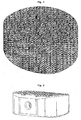
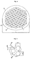
- substantially parallel channels have proven to be advantageous, which are connected by wedge-shaped longitudinal sections along the longitudinal axis of the channels, as in FIG. 2 . 3 and 4 shown.
- the honeycomb structure i. the inner channel structure rises slightly above the substantially flat bone-contacting surface. If the honeycomb structure protrudes beyond a solid edge, in particular in the case of such implants, the advantages of high surface friction and thus very good anchoring and, at the same time, the possibility of mechanical movement due to the small thickness of the honeycomb walls result, which promotes the growth stimulus of the bone.
- the walls between the individual channels i. the honeycomb walls or duct walls have a thickness of 1 ⁇ m to 3,000 ⁇ m, preferably 5 ⁇ m to 1,000 ⁇ m, more preferably 10 ⁇ m to 500 ⁇ m and particularly preferably 50 ⁇ m to 250 ⁇ m.
- the openings in the inner channel structure are arranged such that the entire structure allows micro-movements, preferably friction movements.
- Such movements allow a structure as in FIG. 2 in which the individual channels are connected by wedge-shaped longitudinal sections in the lateral wall regions along the longitudinal axis of the channels.
- the individual can Channel walls are shifted according to the thickness of the wedge-shaped openings against each other, so that micro-movements are possible.
- the bone growth stimulating surface designs of implants are still an object of research, without having previously led to a satisfactory result.
- the above-described raised honeycomb structure with the ability to micro-movements, in particular micro-friction movements seems to represent the long-sought solution to stimulate bone growth in an optimal manner and lead to a rapid penetration of the entire implant.
- This channel structure according to the invention for the bone-contacting, bone-connecting or bone-bridging implants has surprisingly proven to be very advantageous with respect to ingrowth of bone tissue and firm ingrowth with the contacted bone.
- honeycomb structure according to the invention combines the properties of good mechanical stability with optimum filling volume obtained at the same time, so that a rapid and stable penetration of the implant takes place with bone.
- Bone tissue typically comprises three cell types, the osteoblasts, the osteocytes, and the osteoclasts, with the formed bone also having a bone cover layer of bone cover cells.
- the presence of blood is essential for optimal bone formation.
- the osteoblasts, osteocytes and osteoclasts work together.
- Osteoblasts are bone-producing cells responsible for building and maintaining the bone. Non-active osteoblasts on the bone surface are called bone cover cells.
- Osteocytes are former osteoblasts that are built into bone tissue through the process of ossification. They ensure the preservation of the bone by adapting the bone breakdown to the structure.
- Osteoclasts are responsible for the breakdown of the bone. It allows the thickness of the bone to be determined and calcium and phosphate released from the bone.
- the osteoblasts are cells responsible for bone formation. They develop from undifferentiated mesenchymal cells, embryonic connective tissue cells. They attach themselves to bones like skin layers and indirectly form the basis for new bone substance, the bone matrix, in that they mainly excrete calcium phosphates and carbonates into the interstitial space. In this process, they change to a skeleton of unstable osteocytes, which are slowly mineralized and filled with calcium.
- the channel structure according to the invention seems to favor the inflow of blood and thus osteoblasts, which rapidly fill the channel spaces and lead to a significantly better ingrowth of the implant with the bone than conventional implants are able to.
- inventively designed implants have the advantage over porous structures and sponges, for example, that they are less deformable and dimensionally stable, have a defined shape and surface and can be handled and implanted by conventional implantation tools, without running the risk implant, or the channel-like structure in the implant to disregard or damage.
- the inner surfaces of the channels can still be structured, including, for example, a mechanical, chemical or physical roughening counts.
- it can be provided with antibiotics and the outer surface of the outer shell, for example, with a drug-releasing coating, wherein active ingredients such as antibiotics can be stored and continuously released.
- Example 1 relates to a cage, in particular a cervical cage with a longitudinal diameter of 14 mm and a transverse diameter of 12 mm and a height of 8 mm.
- the cage is approximately oval and the longitudinal diameter is understood to be the largest possible diameter and the transverse diameter the smallest possible diameter.
- the cage is made of titanium with a solid at least 1.1 mm thick outer shell and an upper and lower flat surface for contact with the respective vertebral body.
- a honeycomb-shaped structure of channels with hexagonal walls is formed inside the cage.
- the channels extend rectilinearly from the upper bone contacting surface to the lower opposing planar surface contacting the other vertebral body.
- the channels have a diameter given as the distance between two opposing parallel wall surfaces of 870-970 ⁇ m.
- the channels are also connected via recesses in the channel walls.
- the recesses have a wedge-shaped structure, as in FIG. 2 shown, so that the channel walls can be shifted laterally only by the thickness of the recess against each other, which contributes to an increase in the stability of the implant.
- the recess has a thickness of 60 microns.
- Example 2 relates to a cage, in particular a cervical cage with a longitudinal diameter of 16 mm and a transverse diameter of 13 mm and a height of 9 mm.
- the cage is approximately oval and the longitudinal diameter is understood to be the largest possible diameter and the transverse diameter the smallest possible diameter.
- the cage is made of zirconium with a solid 1.2 mm thick outer shell and an upper and lower surface for contact with the respective vertebral body.
- the upper edge of the outer shell is flat and serves to support the upper vertebral body.
- the inner channel structure rises from the edge of the outer shell in a convex shape up to 4 mm beyond the edge of the outer shell, so that the channel structure in the middle of the cage can press up to 4 mm into the underside of the resting vertebral body.
- the inner honeycomb or channel structure extends like a part of a spherical surface in a convex shape in the direction of the upper surface of the underlying vertebral body and digs also in the central region up to 4 mm and in the edge regions correspondingly less in the lower vertebral body.
- a honeycomb-shaped structure of round channels is formed inside the cage.
- the channels extend straight from the upper surface contacting the upper vertebral body to the lower surface contacting the opposite vertebral body. There are about 40 channels per cm 2 bone-contacting surface.
- the channels have a diameter of 850 ⁇ m and the wall thickness of the channel walls is 350 ⁇ m.
- the channels are also connected to each other via recesses in the channel walls, which are designed in the form of longitudinal sections. These longitudinal sections cut through the channel wall in its entire length. However, the longitudinal sections do not cut the channel wall on the shortest path, which is 350 microns, but cut the channel wall obliquely over a distance of about 370 microns in eg east-west direction. The opposite side of the canal we cut again by means of longitudinal section obliquely over a distance of about 370 microns, but now in west-east direction. The thickness of the longitudinal section, ie the connecting channel is 50 microns.
- honeycomb structure allows micro-movements and burrows in upright and underlying vertebral bodies up to a maximum of 4 mm and can stimulate bone growth very start, so that a rapid and good penetration of the implant takes place with newly formed bone.
- Example 3 relates to a cage, in particular a thoracic cage with a longitudinal diameter of 10 mm and a transverse diameter of 8.8 mm and a height of 6.5 mm.
- the cage is approximately oval and the longitudinal diameter is understood to be the largest possible diameter and the transverse diameter the smallest possible diameter.
- the cage consists of medical PEEK with a solid at least 0.9 mm thick outer sheath and an upper and lower flat surface for contact with the respective vertebral body, the top as well as the underside of the caged jagged or toothed with a tooth height of about 0.5 mm.
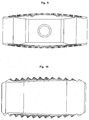
- Such configured top and bottom are, for example, in FIG. 4 and FIG. 10 shown.
- a channel-shaped structure is formed by channels with quadrangular walls.
- the channels extend rectilinearly from the upper bone contacting surface to the lower opposing planar surface contacting the other vertebral body.
- the channels have a diameter given as the distance between two opposite parallel wall surfaces of about 800 microns.
- the channels are also connected via recesses or cuts in the channel walls.
- the recesses or cuts have a rectilinear structure and sever the channel walls in the shortest path, wherein only mutually parallel channel walls are severed, so that no channel wall components are dissolved out of the channel-like structure.
- the recesses or cuts have a thickness of 30 microns.
- the cage according to Example 4 is made of titanium and has the dimensions of the cage according to Example 1 and also has a toothed top and a serrated underside with a maximum tooth height of 0.75 mm.
- the recesses in the channel walls are not wedge-shaped and do not extend over the entire length of the channel wall.
- the recesses are designed as oval slots in the channel walls with a transverse diameter of 7 microns and a longitudinal diameter of 20 microns.
Landscapes
- Health & Medical Sciences (AREA)
- Orthopedic Medicine & Surgery (AREA)
- Engineering & Computer Science (AREA)
- Biomedical Technology (AREA)
- Life Sciences & Earth Sciences (AREA)
- Veterinary Medicine (AREA)
- Public Health (AREA)
- General Health & Medical Sciences (AREA)
- Heart & Thoracic Surgery (AREA)
- Animal Behavior & Ethology (AREA)
- Cardiology (AREA)
- Vascular Medicine (AREA)
- Transplantation (AREA)
- Oral & Maxillofacial Surgery (AREA)
- Neurology (AREA)
- Surgery (AREA)
- Nuclear Medicine, Radiotherapy & Molecular Imaging (AREA)
- Medical Informatics (AREA)
- Molecular Biology (AREA)
- Prostheses (AREA)
- Materials For Medical Uses (AREA)
Description
- Die vorliegende Erfindung betrifft Zwischenwirbelimplantate, sogenannte Cages, mit einer inneren kanalartigen Struktur.
- Im Stand der Technik sind massive als auch hohle Implantate insbesondere für den Wirbelsäulenbereich bekannt, welche entweder aufgrund ihrer massiven Struktur das Einwachsen von Knochenzellen nicht zulassen oder einen zu großen Hohlraum bieten, der nicht vollständig mit körpereigenen Knochenzellen innerhalb vertretbarer Zeit ausgefüllt werden kann und daher in der Regel mit Knochenersatzmaterial oder Knochensplittern künstlich befüllt wird.
- Ziel einer Fusion beispielsweise mittels Cages im Wirbelsäulenbereich ist die knöcherne Durchbauung, da man eine möglichst langfristige Stabilität erreichen möchte. Durchbaut der Knochen das Implantat so erreicht man den Vorteil, dass sich die Knochenzellen wie sonst im Körper auch, erneuern können und somit die Langfristigkeit gewährleistet ist. Die Cages dienen somit als vorübergehender Platzhalter, damit das Bandscheibenfach nicht einsinkt und somit an Höhe verliert. Deshalb müssen die Cages primär auch die Statik übernehmen, zumindest solange bis die Durchbauung des Implantats stattgefunden hat. Eine zügige und stabile knöcherne Durchbauung eines künstlichen Bandscheibenimplantates wie z.B. eines Cages möchte man grundsätzlich erreichen, da derartige Implantate der natürlichen Bandscheine am nächsten kommen und für den Patienten die vorteilhafteste Ausführungsform darstellen.
- Der Nachteil eines massiven Implantats wie z.B. eines massiven Cages liegt offensichtlicher Weise darin, dass gar keine Durchbauung des Implantats möglich ist, d.h. das Implantat dauerhaft die Stützfunktion übernehmen muss und somit langfristig weniger wirksam ist. Dient ein Implantat als reiner Abstandshalten, so besteht des weiteren die Gefahr, dass das Implantat in den Knochen einsinkt und der gewünschte Abstand nicht mehr gewährleistet ist. Derartige Nachteile könnten z.B. dadurch vermieden werden, dass das Implantat vom Knochen natürlich durchbau wird.
- Als eine Stand der Technik Ausführungsform offenbart
EP 0 621 018 A1 in den Figuren 26 und 27 sowie auf Seite 12 in Beispiel 3 ein Zwischenwirbelimplantat AL mit einem massiven künstlichen Zentralköroer AL1, der beispielsweise aus einer Titanlegierung bestehen kann. Die Flächen des Zentralkörpers AL1, welche den angrenzenden Wirbeln zugewandt sind, wurden jeweils laminiert mit einem formpassenden Bauteil AL2, welches aus miteinander laminierten und unterschiedlich ausgeschnittenen Platten besteht, so dass sich auf der Oberseite aus auch der Unterseite des Zwischenwirbelimplantats AL eine nicht massive Struktur ergibt, in welche neu gebildeter Knochen einwachsen kann. Aufgrund der aufeinander laminierten und unterschiedlich ausgesparten Platten ergibt sich ein Kanalnetzwerk aus vertikal verlaufenden miteinander verbundenen Kanälen, Die aufeinander laminierten ca. 10 Platten bestehen vorzugsweise aus Titan haben jeweils eine Dicke von 100 µm, so dass sich Bauteile AL2 von ca. 1 mm Dicke ergeben. Diese Kanäle verlaufen zwar durch die Bauteile AL2 jedoch nicht durch das gesamte Zwischenwirbelimplantat AL von der Oberseite zur Unterseite, weil der Zentralkörper AL1 massiv ist. - Hohle Implantate wie z.B. hole Cages kommen mit oder ohne Knochenersatzstoffe zur Anwendung. Diese Implantate haben jedoch wiederum den Nachteil, dass der Knochen einen zu großen Hohlraum durchbauen müsste, falls keine Knochenersatzstoffe verwendet werden, um die Implantate zu füllen und daher das Implantat wiederum zu lange die Stützfunktion mit den oben geschilderten Nachteilen übernehmen müsste. Werden Knochenersatzstoffe verwendet, so dienen diese dazu, den Knochenbau anzuregen. Da Blut den Katalysator für die Knochenbildung darstellt, der mit Knochenersatzstoff gefüllte innere Hohlraum des Cages jedoch nicht ausreichend mit Blut versorgt wird, findet ein natürliches Knochenwachstum zur Durchbauung des teilweise mit Knochenersatzstoff gefüllten Cages nur ungenügend statt. Dies hat wiederum zur Folge, dass eine Durchbauung eines zum Teil mit Knochenersatzstoff gefüllten Cages auch nicht in gewünschter Weise stattfindet.
- Ideal wäre daher eine bioresorbierbare künstliche Bandscheibe, welche so lange die Stützfunktion übernimmt, bis der körpereigene Knochen diese ersetzt hat und die Stützfunktionen übernehmen kann. Derartige Ausführungsformen sind aufgrund fehlender geeigneter Materialien bisher nicht realisiert worden. Die liegt zum einen daran, dass keine biologisch abbaubaren Materialien zur Verfügung stehen, welche eine ausreichende Stabilität gewährleisten während sich der Knochen aufbaut und ferner sich nicht in der Abbaugeschwindigkeit ausreichend genau regulieren lassen, weil der Aufbau des Knochens und der Abbau des Implantats mit exakt gleicher Geschwindigkeit erfolgen müssen, damit keine Übergangsstruktur entsteht, welche kollabieren könnte.
- Wünschenswert wären hingegen knochenverbindende oder knochenüberbrückende Implantate, welche zum einen eine ausreichende mechanische Stabilität bieten und zudem möglichst vollständig mit körpereigenem Knochen durchbaut bzw. durchwachsen werden können.
- Aufgabe der vorliegenden Erfindung ist somit die Bereitstellung von Zwischenwirbelimplantaten, welche das Einwachsen von körpereigenem Knochen bestmöglich fördern, um dadurch den körpereigenen Knochenaufbau bestmöglichst zu unterstützen und bis zum Aufbau des körpereigenen Knochens ausreichende Stabilität gewährleisten.
- Diese Aufgabe wird durch die Bereitstellung eines Implantats gemäß Patentanspruch 1 gelöst. Weitere vorteilhafte Ausgestaltungen, Aspekte und Details der Erfindung ergeben sich aus den abhängigen Ansprüchen, der Beschreibung, den Beispielen und den Figuren.
- Die vorliegende Erfindung betrifft metallische knochenverbindende oder knochenüberbrückende Zwischenwirbelimplantate in Form von künstlichen Bandscheiben, wobei die künstlichen Bandscheibenimplantate zumindest eine den Knochen kontaktierende Oberfläche und eine innere Struktur aus einer Vielzahl an Kanälen mit definierten Querschnittsflächen oder Radien aufweisen und die Kanäle zudem über Öffnungen miteinander verbunden sind, so dass ein dreidimensionales Kanalnetz entsteht.
- Es wurde überraschend gefunden, dass knochenverbindende oder knochenüberbrückende Bandscheibenimplantate besonders gut mit dem kontaktierten Knochen verwachsen, wenn die Oberfläche des Implantats nicht glatt oder nicht rau oder nicht porös ist, sondern eine Kanalstruktur aufweist, wobei die Kanäle untereinander durch Öffnungen verbunden sind und eine definierte Struktur besitzen. Die Art als auch die Symmetrie der Kanalstruktur ist erfindungswesentlich und wird weiter unten ausführlich beschrieben.
- Daher betrifft die vorliegende Erfindung ein Zwischenwirbelimplantat, wobei das Implantat zwei Oberflächen zur Kontaktierung von zwei Wirbelkörpern, einen äußeren Mantel und eine innere Struktur aufweist und wobei die innere Struktur aus einer Vielzahl von Kanälen gebildet wird und die Kanäle jeweils eine Querschnittsfläche von 8.000 µm2 bis 7.000.000 µm2 besitzen und die Kanäle parallel zueinander entlang der Längsachse der Wirbelsäule verlaufen und die Kanäle über Öffnungen miteinander verbunden sind, dadurch gekennzeichnet, dass jeder Kanal durch mindestens zwei Öffnungen mit benachbarten Kanälen verbunden ist und sich die Öffnungen durchgehend von einer knochenkontaktierenden Oberfläche zur gegenüberliegenden Oberfläche in Form von Schnitten erstrecken.
- Unter dem Begriff "knochenverbindend" oder "knochenüberbrückend" wird verstanden, dass das Implantat direkt mit einem Knochen in Verbindung steht also zumindest ein Teil der Oberfläche des Bandscheibenimplantats mit einem Knochen in Berührung kommt.
- Als Beispiele solcher Bandscheibenimplantate oder Wirbelzwischenimplantate sind insbesondere Cages für die cervicale-, thorakale- oder lumbale Anwendung (wie bspw. ALIF-Cages, PLIF-Cages und TLIF-Cages) zu nennen. Die erfindungsgemäßen Wirbelzwischenimplantate werden auch als Zwischenwirbelkörperelement oder Implantate zur intersomatischen Fusion oder als Implantate zur interkorporellen Wirbelkörperfusion bezeichnet.
- Die vorgenannten Implantate sind in der Regel vollständig aus einem harten Material, insbesondere einem Metall oder einer Metalllegierung wie beispielsweise Titan, Zirkonium, oxidiertem Zirkonium, Hafnium, Platin, Rhodium, Niobium, medizinischem Edelstahl, CoCr-Stahl (Cobalt-Crom), Tantal und können aber auch aus faserverstärkten Kunststoffen (Glas- / Carbonfasem mit entsprechender Matrix), PEEK [Poly(etheretherketone)] oder Polymerwerkstoffen allgemein bestehen. Bei den Metalllegierungen können ferner Metalle wie Aluminium, medizinischer Stahl und/oder Gold zugesetzt werden.
- Einteilige Bandscheibenimplantate wie die erfindungsgemäßen Cages, welche auch als Wirbelzwischenimplantat bezeichnet werden, weisen in der Regel einen massiven Außenmantel ohne Kanalstruktur auf, um eine ausreichende Stabilität des Implantates zu gewährleisten. Der Begriff "massiv" wie hierin verwendet bedeutet, dass der Außenmantel gar keine Öffnungen also auch keine Öffnungen von Kanälen der erfindungsgemäßen Kanalstruktur oder Öffnungen von Verbindungskanälen zwischen den Kanälen der erfindungsgemäßen Kanalstruktur aufweist bis hin zu einer solchen Anzahl an Öffnungen von Kanälen oder Verbindungskanälen der erfindungsgemäßen Kanalstruktur, dass der Außenmantel bei dem 5-fachen bevorzugt bei dem 8-fachen und insbesondere bevorzugt bei dem 10-fachen durch die Wirbelsäule ausgeübten Druck in Richtung der Längsachse der Wirbelsäule nicht deformiert wird, d.h. die Öffnungen nicht zusammengedrückt werden.
- Die erfindungsgemäße Kanalstruktur im Inneren des Cages bzw. des künstlichen Bandscheibenimplantats dient zur gezielten Anregung des Knochenwachstums und weniger zur Stabilisierung des gesamten Implantats. Die mechanische Stabilität wird dem Wirbelzwischenimplantat, dem Cage, durch einen Außenmantel verliehen, welcher zum einen ausgestaltet ist, um den hohen Drücken der Wirbelsäule Stand zu halten und das Einsinken des Implantats in den Wirbelknochen verhindert, so dass der durch die Höhe des Außenmantels definierter Abstand zwischen zwei Wirbelkörper aufrecht erhalten werden kann. Somit ist der Außenmantel, d.h. der Teil des Bandscheibenimplantats, der die innere Kanalstruktur umgibt, massiv und nicht Teil der inneren Kanalstruktur. Der Begriff "massiv" soll so verstanden werden, dass dieser Außenmantel vorzugsweise nicht von Kanälen durchzogen ist, sich darin keine Löcher befinden und keine Kanäle durch den Außenmantel verlaufen und auf dessen Außenfläche enden. Somit kann vorzugsweise auch kein Blutfluß durch den Außenmantel hindurch stattfinden. Der Außenmantel verliert mit der Zeit seine Stützfunktion je mehr die innere Kanalstruktur mit Knochen durchwachsen wird.
- Der Außenmantel kann auch als corticale Außenwand des Zwischenwirbelimplantates bezeichnet werden. Die Zwischenwirbelimplantate, die zur intersomatischen Fusion eingesetzt werden, sollten idealerweise der Grundfläche der angrenzenden Wirbelkörper entsprechen.
- Der für die knöcherne Durchbauung zur Verfügung stehende Raum soll zudem maximiert werden aber dennoch von körpereigenen Knochenzellen zügig durchwachsen werden können. Gleichzeitig muss im ersten Moment der Versorgung, d.h. nach der Implantation das Implantat die Statik übernehmen und es muss verhindert werden, dass das Implantat dem Wirbelkörper zu wenig Unterstützungsfläche bietet und es deshalb unter Lasteinwirkung in den Wirbelkörper einsinkt.
- Die insbesondere lasttragende Struktur des Wirbelkörpers ist die zirkulär umlaufende Corticalis. Im Idealfall kommt die massive Wandung des Cages zwischen den zirkulär verlaufenden Corticaliswänden der angrenzenden Wirbelkörper zu liegen, sodass der Corticalis eine Unterstützungsfläche zur Verfügung steht, die ein Einsinken des Cages in den Wirbelkörper verhindert.
- Im Bereich der Spongiosa, d.h. dem gut durchbluteten Knochen zentral im Wirbelkörper gelegen, liegt die wabenartige Struktur des Cages, um eine ideale knöcherne Durchbauung zu gewährleisten.
- Die erfindungsgemäßen Implantate können nach Standardtechniken hergestellt werden, beispielsweise unter Verwendung von Lasertechnologie und Laserschneidverfahren sowie Laserschmelzverfahren, z.B. Lasercusing und demnach im Rahmen der beschriebenen Erfindung beliebige Gestalt annehmen.
- Die erfindungsgemäßen Cages sind somit vorzugsweise einteilig, bestehen vollständig oder zumindest zu 90 Gew.-% aus Metall oder einer Metalllegierung, sind nicht porös wie beispielweise Keramiken es sein können, sondern weisen eine definierte innere Kanalstruktur auf, welche den Blutfluß unterstützt und damit die besten Vorraussetzungen für körpereigenes Knochenwachstum schafft und weisen einen äußeren Mantel auf, der für die Stabilitätsgebung zumindest so lange verantwortlich ist, solang der neugebildete Knochen diese Funktion noch nicht übernehmen kann.
- Der Begriff "einteilige Bandscheibenimplantate" oder "einteilige Cages" bezieht sich nur auf das Implantat selbst und nicht auch auf irgendwelche Befestigungsmittel. Derartige Bandscheibenimplantate können beispielweise in die angrenzenden Wirbelkörper verschraubt werden. Die verwendeten Befestigungsmittel wie z.B. Schrauben werden bei dem Begriff "einteilig" nicht berücksichtigt und werden als Zubehör zu dem erfindungsgemäßen Bandscheibenimplantat bezeichnet wie auch das Implantationswerkzeug. Ferner sind natürliche Materialien wie beispielsweise natürliches Knochenmaterial bei dem erfindungsgemäßen Bandscheibenimplantat kein Bestandteil und bei dessen Implantation muss oder wird auch kein künstlichen Knochenmaterial verwendet. Die erfindungsgemäßen Cages sind somit gemäß dieser Definition vorzugsweise einteilig. Zweiteilige Ausführungsformen sind auch noch möglich, wobei die erfindungsgemäßen Implantate aus maximal drei Teilen vorzugsweise sogar aus nicht mehr als zwei Teilen bestehen, wobei die weiteren Teile in der Regel am Cage vorgesehene Befestigungsmittel betreffen wie beispielsweise entfernbare Platten für Befestigungsschrauben oder Befestigungshaken oder Befestigungskrallen oder dergleichen, welche in der Regel optional an den erfindungsgemäßen Implantaten vorgesehen werden können.
- Die erfindungsgemäßen Implantate sind nicht nach einem Baukastenprinzip oder aus mehreren Einzelteilen oder Teilstücken zusammengesetzt, welche sich eventuell nur schwer miteinander verbinden lassen oder gegeneinander translationsbeweglich, rotationsbeweglich oder gleitend verschieben können und besitzen einen Außenmantel mit definierter Form, der nach der Implantation seine Form und Maße nicht mehr verändert.
- Eine Möglichkeit besteht jedoch darin, die innere Wabenstruktur oder Kanalstruktur separat von dem Außenmantel zu fertigen und nach getrennter Fertigung zusammen zu fügen, so dass letztendlich auch wieder ein einteiliges Implantat vorliegt. Wie oben beschrieben ist der Außenmantel massiv, d.h. es dürfen maximal so viele Aussparungen, Löcher oder Öffnungen darin enthalten sein, dass eine Deformation durch den Wirbelsäulendruck bis zum Zeitpunkt der vollständigen Durchbauung mit körpereigenem Knochen nicht stattfinden kann. Bevorzugt ist, dass der massive Außenmantel keinerlei Aussparungen, Löcher oder Öffnungen aufweist.
- Die erfindungsgemäße Kanalstruktur beginnt an der knochenkontaktierenden Fläche des Implantats, so dass die Öffnungen der Kanäle dem Knochen zugewandt sind, d.h. die oberen Öffnungen sind dem oberen kontaktierten Wirbelkörper zugewandt und die unteren Öffnungen der Kanäle dem unteren Wirbelkörper.
- Bei knochenverbindenden oder knochenüberbrückenden Implantaten des Wirbelsäulenbereichs wie auch bei den erfindungsgemäßen Implantaten sind die Kontaktflächen der Implantate mit dem jeweiligen Knochen in der Regel eben und die Kanäle erstrecken sich entlang der Wirbelsäulenlängsachse von der Knochenkontaktfläche weg.
- Als Kontaktfläche wird die Fläche des Cages verstanden, welche mit dem aufliegenden Wirbelkörper sowie die gegenüberliegende Fläche des Cages, welche mit dem unterliegenden Wirbelkörper in Berührung kommt.
- Die Kontaktfläche mit dem Knochen muss jedoch nicht eben ausgestaltet sein, wie es bei den Wirbelzwischenimplantaeten des Standes der Technik der Fall ist, sondern kann auch eine unsymmetrische Form besitzen. Es ist durchaus weiter bevorzugt, wen sich die innere Kanalstruktur geringfügig über den Außenmantel in Richtung des aufliegenden Wirbelkörpers als auch in Richtung des unterliegenden Wirbelkörpers erstreckt wie weiter unter noch ausführlicher ausgeführt wird. Der sich über den Außenmantel hinaus erstreckende Teil der inneren Kanalstruktur sinkt oder drückt sich in den aufllegenden bzw. den unterliegenden Wirbelkörper ein und führt damit zu einer gewollten Verletzung der Oberfläche dieser beiden Wirbelkörper, wodurch das Knochenwachstum aus auch der Blutfluß abermals gesteigert werden.
- Somit beginnen die Kanäle an der knochenkontaktierenden Oberfläche des Implantats, wobei die innere Kanalstruktur eine ebene Oberfläche zum aufliegenden Wirbelkörper als auch eine ebene Oberfläche zum unterliegenden Wirbelkörper aufweisen kann. Bevorzugt ist jedoch eine konvexe, d.h. zum Wirbelkörper gerichtete Krümmung der Oberfläche der inneren Kanalstruktur, wobei die kontaktierende Oberfläche zum aufliegenden Wirbelkörper konvex ausgestaltet sein kann und/oder die den unterliegenden Wirbelkörper kontaktierende gegenüberliegende Oberfläche der inneren Kanalstruktur konvex ausgestaltet sein kann. Die konvexe Krümmung der inneren Kanalstruktur hat eine Höhe gemessen am höchsten Punkt der Krümmung von 0,1 mm bis 5 mm.
- Erfindungswesentlich ist, dass die einzelnen Kanäle oder zumindest 75% aller Kanäle, bevorzugt zumindest 85% aller Kanäle und insbesondere bevorzugt mindestens 95% aller Kanäle eine Querschnittsfläche im Bereich von 8.000 µm2 bis 7.000.000 µm2, bevorzugt von 50.000 µm2 bis 3.100,000 µm2, weiter bevorzugt im Bereich von 100.000 µm2 bis 800.000 µm2, noch weiter bevorzugt im Bereich von 125.000 µm2 bis 650.000 µm2 und insbesondere bevorzugt im Bereich von 160.000 µm2 bis 570.000 µm2 aufweisen.
- Der Ausdruck, dass 85% aller Kanäle eine Querschnittsfläche innerhalb der vorgenannten Bereiche aufweisen bedeutet, dass von 100 Kanälen 85 Kanäle eine Querschnittsfläche im vorgenannten Bereich haben und die restlichen 15 Kanäle eine kleine oder größere als auch eine deutlich kleinere oder deutliche größere Querschnittsfläche aufweisen können.
- Die Kanäle können eine beliebige Form aufweisen und rund, oval, dreieckig, viereckig, fünfeckig, sechseckig, siebeneckig, achteckig oder beliebig vieleckig ausgestaltet sein. Bevorzugt sind jedoch Ausgestaltungen mit Innenwinkeln größer als 90°, also begonnen mit einem Fünfeck über ein Vieleck bis hin zum Kreis oder einem Oval. Weiter bevorzugt sind fünfeckige, sechseckige, siebeneckige und achteckige Ausgestaltungen und insbesondere sechseckige Kanäle.
- Bei runden Kanälen ist die Querschnittsfläche gleich der Kreisfläche und kann einfach gemäß πr2 berechnet werden, wobei r der Radius des Kanals ist.
- Bezogen auf runde oder annähernd runde Kanalformen ist bevorzugt, wenn die Kanäle oder zumindest 75% aller Kanäle, bevorzugt zumindest 85% aller Kanäle und insbesondere bevorzugt mindestens 95% aller Kanäle einen Durchmesser von 100 - 3000 µm, bevorzugt 250 - 2000 µm, weiter bevorzugt 350 - 1000 µm, noch weiter bevorzugt 400 - 900 µm und insbesondere bevorzugt 450 - 850 µm aufweisen.
- Bei mehreckigen Kanalformen wird als Durchmesser der Abstand von zwei gegenüberliegenden parallelen Flächen bei geradzahligen Vielecken (viereckig, sechseckig, achteckig usw.) oder der Abstand eines Eckpunktes zum Mittelpunkt der gegenüberliegenden Geraden bei ungeradzahligen Vielecken (Dreieck, Fünfeck, Siebeneck usw.) bezeichnet.
- Die Wandstärke der Kanalwände beträgt 20 µM bis 700 µM, vorzugsweise 30 µM bis 550 µM und weiter bevorzugt 40 µM bis 400 µM. Der Durchmesser der Kanäle beträgt vorzugsweise das 2-fache bis 4-fache der Kanalwandstärke (Kanalwanddicke). Der Außenmantel weist eine Dicke von 500 µM bis 1.500 µM, vorzugsweise von 700 µM bis 1.300 µM und insbesondere bevorzugt von 850 µM bis 1.100 µM auf. Die Dicke des Außenmantels entspricht vorzugsweise dem 1-fachen bis 2-fachen Durchmesser der Kanäle. Die Dicke der Einschnitte oder Verbindungskanäle oder der Durchmesser der Öffnungen beträgt vorzugsweise ein Drittel bis ein Zehntel der Wandstärke der Kanäle.
- Kanäle mit vorgenanntem Durchmesser oder vorgenannter Querschnittsfläche erstrecken sich also von der Fläche des Implantats, welche an dem Knochen anliegt, in das Implantatinnere. Bei den vorzugsweise einteiligen erfindungsgemäßen Implantaten mit gegenüberliegenden knochenkontaktierenden Flächen wie den erfindungsgemäßen Cages erstrecken sich vorzugsweise die Kanäle durch das Implantat bis zur gegenüberliegenden knochenkontaktierenden Fläche.
- Bei den erfindungsgemäßen Implantaten enden die Kanäle vorzugsweise nicht auf der Höhe des äußeren Mantels, sondern gehen bis maximal zu 10 mm über dessen Höhe hinaus.
- Die Ausgestaltung der Kanäle ist erfindungswesentlich und das erfindungsgemäße Kanalnetzwerk folgt einer Symmetrie. Es sei angemerkt, dass ein zufällig entstandenes Kanalnetzwerk, wie es beispielweise ohne Symmetrie in porösen Strukturen oder Schwämmen vorliegt, die erfindungsgemäße Aufgabe nicht löst. Gleiches gilt für Kanäle, welche sprunghaft ihre Richtung und ihren Durchmesser ändern oder sich aufgrund mehrlagiger Systeme zufällig und/oder in willkürlicher Abfolge und/oder Form ergeben. Bei derartigen Systemen zeigt sich, dass der Blutfluss nur in Teilbereichen verstärkt wird und sich nur in Teilbereichen oder punktförmig Knochenzellbildungen zeigen, ein Durchwachsen des gesamten Implantats mit Knochenzellen teilweise nicht oder insgesamt nur verlangsamt stattfindet.
- Erfindungsgemäß verlaufen die Kanäle im wesentlichen parallel zueinander und sind geradlinig, d.h. die Kanäle weisen keine Biegungen, Kurven, Krümmungen oder ähnliches auf, sonder verlaufen von ihrer Öffnung auf einer äußeren Fläche des Implantats im wesentlichen parallel in das Implantat oder eines Teils des Implantats hinein und enden im Inneren des Implantats oder verlaufen vorzugsweise durch das Implantat bis zur gegenüberliegenden äußeren Fläche des Implantats. Zudem ändern die Kanäle vorzugsweise weder kontinuierlich noch sprunghaft oder stufenweise ihren Radius oder Durchmesser, ungeachtet, ob es sich um runde, ovale oder mehreckige Kanäle handelt.
- Unter dem Begriff "im wesentlichen parallel" soll verstanden werden, dass gewisse Herstellungstoleranzen vorliegen können und abgesehen von diesen Toleranzen die Kanäle parallel zueinander verlaufen.
- Ferner verändern die Kanäle in ihrem Verlauf nicht ihren Durchmesser, d.h. ebenfalls abgesehen von Herstellungstoleranzen, haben die Kanäle im wesentlichen von ihrem Anfang bis zu ihrem Ende denselben Durchmesser.
- Ferner ist auch nicht zwingend, dass alle Kanäle auf der oder einer knochenkontaktierenden Oberfläche beginnen, d.h. unmittelbar mit dem Knochen in Berührung stehen. Bis zu 30% vorzugsweise bis zu 20% aller Kanäle kann auch in einem Bereich des Implantats beginnen, der nicht direkt mit dem Knochen in Berührung steht, d.h. vorzugsweise beginnen diese Kanäle seitlich der knochenkontaktierenden Oberfläche.
- Hingegen ist nicht erforderlich, dass die Kanäle auch an einer knochenkontaktierenden Oberfläche enden, was sowieso nur bei einteiligen knochenverbindenden oder knochenüberbrückenden Implantaten der Fall wäre. Bis zu 100% aller Kanäle können auch einer nicht einen Knochen kontaktierenden Oberfläche enden, wobei es jedoch auch möglich ist, dass bis zu 100% der Kanäle auf einer gegenüberliegenden anderen knochenkontaktierenden Oberfläche enden, was aus herstellungstechnischen Gründen für die einteiligen erfindungsgemäßen Cages bevorzugt ist.
- Zudem ist bevorzugt, wenn abgesehen von dem massiven Außenmantel des erfindungsgemäßen Implantats, pro cm2 knochenkontaktierender Oberfläche mindestens 50 Kanäle, vorzugsweise mindestens 100 Kanäle und insbesondere bevorzugt mindestens 150 Kanäle anfangen. Die erfindungsgemäße Kanalstruktur weist zwischen 20 und 1000 Kanäle pro cm2 auf, vorzugsweise zwischen 50 und 750, weiter bevorzugt zwischen 100 und 500, noch weiter bevorzugt zwischen 125 und 350 und insbesondere bevorzugt zischen 150 und 250 Kanäle pro cm2 auf.
- Zudem ist erfindungswesentlich, dass die einzelnen Kanäle untereinander verbunden sind. Die Kanäle werden durch Öffnungen miteinander verbunden, wobei jeder Kanal zumindest eine Öffnung zu einem angrenzenden Kanal hat. Ferner ist bevorzugt, wenn die äußeren Kanäle, d.h. diejenigen Kanäle, welche die äußere Reihe der gesamten kanalartigen Struktur bilden und an den massiven Außenmantel grenzen, zumindest eine Öffnung zu einem benachbarten Kanal besitzen und die Kanäle, welche im Inneren der kanalartigen Struktur liegen zumindest eine Öffnungen zu zwei verschiedenen angrenzenden Kanälen besitzen, d.h. also absolut mindestens zwei Öffnungen aufweisen.
- Zudem ist bevorzugt, wenn die Öffnungen so angeordnet werden, dass alle Kanäle miteinander verbunden sind, d.h. theoretisch über eine Öffnung eines Kanals das gesamte kanalartige System mit Flüssigkeit wie z.B. Blut gefüllt werden könnte. Man erzeugt also vorzugsweise eine dreidimensionale Interkonnektivität der gesamten Struktur.
- Die Öffnungen oder auch Verbindungskanäle genannt, können beliebig ausgestaltet sein und in Form von Löchern oder Schnitten vorliegen, rund, kreisförmig, punktförmig, zylinderförmig, oval, eckig, keilförmig oder eine andere beliebige Ausgestaltung aufweisen.
- Es ist darüber hinaus bevorzugt, dass auch die Öffnungen zwischen den Kanälen einem Muster, d.h. einer Symmetrie oder einer wiederkehrenden Anordnung folgen. Somit ist bevorzugt, dass die Öffnungen zwischen den Kanälen entweder entlang der Längsachse der Kanäle verlaufen und die Öffnungen eine maximale Länge aufweisen können, welche der Länge der miteinander verbundenen Kanäle entspricht. Bei dieser Art von Öffnungen, welche entlang der Längsachse der Kanäle verlaufen, handelt es sich vorzugsweise um Einschnitte vorzugsweise keilförmige Einschnitte in die Kanalwandungen bzw. Kanalwände.
- Eine andere Art von Öffnungen ist vorzugsweise rund oder oval ausgestaltet und verläuft senkrecht zur Längsachse der Kanäle. Die Längsachse der Kanäle verläuft in Richtung der Längsachse der Wirbelsäule. Diese Öffnungen werben beispielsweise per Laser in das Implantat geschnitten und verlaufen durch die Außenwand des Implantats in Richtung der gegenüberliegenden Fläche und verbinden so die auf dieser Geraden liegenden Kanäle untereinander. Um die oben beschriebene Stabilität zu gewährleisten, können die Öffnungen oder Verbindungskanäle auch im Innern des Cages aufhören, ohne den gegenüberliegenden Außenmantel zu durchdringen. Somit ist bevorzugt, dass diese Verbindungskanäle durch den Außenmantel gehen und vor der Innenfläche des gegenüberliegenden Außenmantels enden. Bevorzugt sind jedoch Öffnungen oder Einschnitte, welche entlang der Mittelachse der Kanäle verlaufen und als Schnitt oder Keilschnitt die Wand eines Kanals entlang seiner Gesamtlänge durchtrennen. Bei derartigen Längsschnitten entlang der Kanalwand Werden diese selbstverständlich so angeordnet, dass durch mehrere Schnitte in benachbarten Kanalwänden keine Teilstücke von Kanalwänden aus der Gesamtstruktur herausgetrennt werden. Betrachtet man hierzu
Figur 2 mit den sechseckigen Kanälen und den keilförmigen Verbindungskanälen oder Einschnitten, so könnte man die Kanalwände in laterale Wandbereicht und anteriore-posteriore Wandbereicht unterteilen. InFigur 2 sind beispielsweise nur die lateralen Wandbereiche eingeschnitten, so dass alle Kanalwände mindestens an zwei Stellen mit dem massiven Außenmantel verbunden sind und kein Wandsegment auch nicht ein Segment aus mehreren Kanalwandbereichen von mehreren Kanälen aus der Gesamtkanalstruktur herausgeschnitten oder herauslösbar ist. - Der Durchmesser oder die Dicke der Öffnungen liegt im Bereich von 0,1 µM bis 1000 µm, vorzugsweise im Bereich 1 µM bis 500 µM, weiter bevorzugt 10 µM bis 200 µM, noch weiter bevorzugt im Bereich von 30 µM bis 100 µM und insbesondere bevorzugt im Bereich von 50 bis 80 µm.
- Ferner können sich die Öffnungen entlang der Längsachse der Kanäle erstrecken, was als durchgehend bezeichnet wird und sogar von einer knochenkontaktierenden Oberfläche bis zur gegenüberliegenden knochenkontaktierenden Oberfläche verlaufen und somit die Länge der Kanäle selbst besitzen.
- Die Öffnungen können zudem in Form von Bohrungen senkrecht zur Längsachse der Kanäle durch das Implantat verlaufen oder als nach bestimmten Abständen wiederkehrende Öffnungen in den Kanalwänden die Kanäle miteinander verbinden.
- Die Ausgestaltung der Kanäle an sich ist nicht erfindungswesentlich, sondern deren Vorhandensein. Es versteht sich für einen Fachmann, dass zu viele Öffnungen die Stabilität des Implantats beeinträchtigen können, so dass ein Fachmann Anzahl, Größe und Lage der Öffnungen nach der Art des Implantats versteht zu bestimmen.
- Ferner sollte der Durchmesser oder die Dicke der Öffnungen kleiner sein, als der Durchmesser oder die Dicke der Kanäle und vorzugsweise weniger als ein Zehntel der Dicke der Kanäle betragen.
- Grundsätzlich könnte man die Öffnungen auch als senkrecht zur Längsachse der Kanäle verlaufende Verbindungskanäle bezeichnen. Die erfindungsgemäße Kanalstruktur besteht ferner vorzugsweise aus im wesentlichen parallel verlaufenden Kanälen, welche ferner vorzugsweise parallel zu den Verbindungskanälen verlaufen.
- Es versteht sich zudem von selbst, dass nicht das gesamte Implantat die erfindungsgemäße Kanalstruktur aufweisen muss, sondern nur die Bereiche eines Implantats, welche mit dem Knochen in Berührung kommen oder insbesondere in den Knochen eingelassen werden. Dennoch ist bei den erfindungsgemäßen Cages oder Zwischenwirbelimplantaten bevorzugt, wenn die Kanalstruktur sich im Innern des Implantats von der Unterseite des aufliegenden Wirbelkörpers bis zur Oberseite des unterliegenden Wirbelkörpers erstreckt. Das Inneren des Implantats wird durch den Außenmantel definiert.
- Bei den Ausführungsformen von Cages haben sich insbesondere durchgehende im wesentlichen parallele Kanäle als vorteilhaft erwiesen, welche durch keilförmige Längsschnitte entlang der Längsachse der Kanäle miteinander verbunden sind, so wie in
Figur 2 ,3 und 4 dargestellt. - Ferner ist bei den erfindungsgemäßen Implantaten bevorzugt, wenn sich die Wabenstruktur, d.h. die innere Kanalstruktur ein wenig über die im wesentlichen ebene knochenkontaktierende Fläche erhebt. Ragt insbesondere bei solchen Implantaten die Wabenstruktur über einen massiven Rand hinaus, ergeben sich die Vorteile einer hohen Oberflächenreibung und damit einer sehr guten Verankerung und gleichzeitig aufgrund der geringen Dicke der Wabenwandungen die Möglichkeit der mechanischen Bewegung derselben, was den Wachstumsreiz des Knochens fördert.
- Die Wände zwischen den einzelnen Kanälen, d.h. die Wabenwandungen oder Kanalwandungen haben eine Dicke von 1 µm bis 3.000 µm, vorzugsweise 5 µm bis 1.000 µm, weiter bevorzugt 10 µm bis 500 µm und insbesondere bevorzugt 50 µm bis 250 µm.
- Zudem ist bevorzugt, dass die Öffnungen in der inneren Kanalstruktur derart angeordnet sind, dass die gesamte Struktur Mikrobewegungen vorzugsweise Friktionsbewegungen zulässt. Derartige Bewegungen ermöglicht z.B. eine Struktur wie in
Figur 2 gezeigt, worin die einzelnen Kanäle durch keilförmige Längsschnitte in den lateralen Wandbereichen entlang der Längsachse der Kanäle miteinander verbunden sind. Dabei können die einzelnen Kanalwandungen entsprechend der Dicke der keilförmigen Öffnungen gegeneinander verschoben werden, so dass Mikrobewegungen möglich werden. - Kombiniert man ferner diese Art der Ausgestaltung der Öffnungen zwischen den Kanälen mit der Ausgestaltung, dass die innere kanalartige Struktur sich wie eine Insel bis zu mehreren Millimetern über die im wesentliche ebene knochenkontaktierende Fläche erhebt, d.h. konvex in Richtung des kontaktierten Wirbelkörpers ausgestaltet ist, so regt dieser bis zu 10 mm erhobene Teilbereich der Wabenstruktur das Knochenwachstum besonders gut an, da sich dieser erhobene Teil in den Knochen leicht eingräbt und durch seine Eigenschaft Mikrobewegungen zuzulassen, den Knochenbewegungen folgen kann und ferner ganz besonders gut das Knochenwachstum durch eine leichte aber kontinuierliche Stimulierung fördert.
- Das Knochenwachstum anregende Oberflächenausgestaltungen von Implantaten sind noch immer ein Gegenstand der Forschung, ohne bisher zu einem befriedigenden Ergebnis geführt zu haben. Die vorher beschriebene erhobene Wabenstruktur mit der Fähigkeit zu Mikrobewegungen, insbesondere Mikrofriktionsbewegungen scheint die lange gesuchte Lösung darzustellen, das Knochenwachstum in optimaler Weise anzuregen und zu einer raschen Durchbauung des gesamten Implantats zu führen.
- Diese erfindungsgemäße Kanalstruktur für die knochenkontaktierenden, knochenverbindenden oder knochenüberbrückenden Implantate hat sich überraschend als sehr vorteilhaft in Bezug auf ein Einwachsen von Knochengewebe und ein festes Verwachsen mit dem kontaktierten Knochen erwiesen.
- Zudem vereint die erfindungsgemäße Wabenstruktur die Eigenschaften guter mechanischer Stabilität bei gleichzeitig erhaltenem optimalem Befüllvolumen, so dass eine rasche und stabile Durchwachsung des Implantats mit Knochen stattfindet.
- Knochengewebe umfasst in der Regel drei Zellformen, die Osteoblasten, die Osteozyten und die Osteoklasten, wobei der ausgebildete Knochen zudem eine Knochendeckschicht aus Knochendeckzellen besitzt. Das Vorhandensein von Blut ist essentiell erforderlich für eine optimale Knochenbildung. Bei der Bildung von Knochen arbeiten die Osteoblasten, Osteozyten und Osteoklasten zusammen. Osteoblasten sind knochenproduzierende Zellen und für den Aufbau und Erhalt des Knochens verantwortlich. Nicht aktive Osteoblasten an der Knochenoberfläche werden Knochendeckzellen genannt. Osteozyten sind ehemaligen Osteoblasten, die durch den Verknöcherungsprozess im Knochengewebe eingebaut sind. Sie sorgen für den Erhalt des Knochens indem sie den Knochenabbau dem Aufbau anpassen. Osteoklasten sind für den Abbau des Knochens verantwortlich. Durch sie kann die Dicke des Knochens bestimmt und Calcium und Phosphat aus dem Knochen freigesetzt werden. Die Osteoblasten sind Zellen, die für die Knochenbildung verantwortlich sind. Sie entwickeln sich aus undifferenzierten Mesenchymzellen, embryonalen Bindegewebszellen. Sie lagern sich an Knochen hautschichtartig an und bilden indirekt die Grundlage für neue Knochensubstanz, die Knochenmatrix, indem sie vor allem Calciumphosphate und -carbonate in den interstitiellen Raum ausscheiden. Bei diesem Prozess verändern sie sich zu einem Gerüst aus nicht mehr teilungsfähigen Osteozyten, das langsam mineralisiert und mit Calcium aufgefüllt wird.
- Die erfindungsgemäße Kanalstruktur scheint das Einfließen von Blut und damit Osteoblasten zu begünstigen, welche zügig die Kanalräume ausfüllen und zu einem deutlich besseren Verwachsen des Implantats mit dem Knochen führen, als herkömmliche Implantate dazu in der Lage sind.
- Zudem besitzen die erfindungsgemäß ausgestalteten Implantate gegenüber beispielsweise porösen Strukturen und Schwämmen den Vorteil, dass sie wenig deformierbar und formstabil sind, eine definierte Gestalt und Oberfläche besitzen und durch herkömmliche Implantationswerkzeuge gehandhabt und implantiert werden können, ohne Gefahr zu laufen, das Implantat oder die kanalartige Struktur im Implantat zu zustören oder zu beschädigen.
- Um das Anhaften von Knochenzellen noch weiter zu begünstigen, können die Innenflächen der Kanäle noch strukturiert werden, wozu beispielsweise eine mechanische, chemische oder physikalische Aufrauung zählt. Um das Wachstum von Bakterien oder anderen Keimen auf der Implantatsoberfläche zu unterdrücken, kann diese mit Antibiotika und die Außenfläche des Außenmantels beispielsweise mit einer wirkstofffreisetzenden Beschichtung versehen werden, worin Wirkstoffe wie beispielsweise Antibiotika eingelagert und kontinuierlich freigesetzt werden können.
-
- Figur 1
- zeigt eine perspektivische Ansicht eines erfindungsgemäßen knochenverbindenden Bandscheibenimplantats wie z.B. eines Cages. Beispielhaft ist das Implantat mit ovaler Form dargestellt, welche jedoch nicht zwingend ist. Die Außenwand des Implantats ist massiv und das Implantat besteht aus einem physiologisch verträglichen Material, insbesondere einem Metall oder einer Metalllegierung. Im inneren Bereich des Implantats ist die wabenförmige Struktur aus durchgehenden Kanälen zu erkennen, welche untereinander durch Öffnungen miteinander verbunden sind,
- Figur 2
- zeigt das erfindungsgemäße Wirbelzwischenimplantat von einer seitlichen Ansicht.
- Figur 3
- zeigt eine Aufsicht des Implantats entlang der Längsachse der Kanäle. Die Seitenwände der Kanäle sind als Wabenmuster zu erkennen und die Öffnungen zwischen den Kanälen sind als keilförmige Einschnitte sichtbar. Zudem ist zu erkennen, dass die Kanäle durchgehend sind, d.h. von der Oberseite des Implantats zur Unterseite durchlaufen.
- Figur 4
- zeigt ein erfindungsgemäßes Wirbelzwischenimplantat von einer perspektivischen Ansicht. Es ist gut die gezahnte Oberseite und auch die gezahnte Unterseite des Implantats erkennbar, welche zur Stabilisierung der Lage des Implantats beiträgt.
- Figur 5
- zeigt nochmals die erfindungsgemäße Wabenstruktur wie in
Figur 3 und markiert einen Ausschnitt, der inFigur 6 vergrößert dargestellt wird. - Figur 6
- zeigt den in
Figur 5 markierten Ausschnitt. Die sechseckige Struktur der Kanäle und die keilförmigen Öffnungen zwischen den Kanälen sowie die Wandungen der Kanäle sind vergrößert dargestellt. - Figur 7
- zeigt eine Ausführungsform eines erfindungsgemäßen Cages mit einer konvexen und gezahnten Oberseite und einer konvexen und gezahnten Unterseite (nicht sichtbar) bzw. einer konvex erhobenen inneren wabenartigen Struktur.
- Figur 8
- zeigt eine weitere Ansicht des erfindungsgemäßen Cages gemäß
Figur 7 , wobei die konvex ausgestaltete Oberseite und die konvex ausgestaltete Unterseite gut zu erkennen sind. - Figur 9
- zeigt eine Frontansicht des erfindungsgemäßen Cages gemäß
Figur 7 mit deutlich erkennbarer konvexer Oberseite und Unterseite. Die mittig gezeigte runde Aussparung dient zur Aufnahme eines Implantationswerkzeugs. - Figur 10
- zeigt eine seitliche Ansicht eines erfindungsgemäßen Wirbelzwischenimplantals mit einer gezahnten Oberseite und gezahnten Unterseite. Die Zahnung befindet sich in der wabenförmigen Struktur als auch im Außenmantel und dient zur Stabilisierung der Lage des Implantats zwischen den Wirbelkörpern nach der Implantation.
- Bevorzugte Ausführungsformen der erfindungsgemäßen Vorrichtung werden nun anhand der Beispiele diskutiert, wobei zu berücksichtigen ist, dass die diskutierten Beispiele vorteilhafte Ausgestaltungen der Erfindung wiedergeben, jedoch den Schutzumfang nicht auf diese Ausführungsformen beschränkten.
- Beispiel 1 betrifft einen Cage, insbesondere einen cervicalen Cage mit einem Längsdurchmesser von 14 mm und einem Querdurchmesser von 12 mm und einer Höhe von 8 mm. Der Cage ist annähernd oval und als Längsdurchmesser wird der größtmögliche Durchmesser und als Querdurchmesser der kleinstmögliche Durchmesser verstanden.
- Der Cage besteht aus Titan mit einem massiven mindestens 1,1 mm dicken Außenmantel und einer oberen und unteren ebenen Fläche für den Kontakt mit dem jeweiligen Wirbelkörper.
- Im Inneren des Cages ist eine wabenförmige Struktur aus Kanälen mit sechseckigen Wandungen ausgebildet. Die Kanäle erstrecken sich geradlinig von der oberen den Knochen kontaktierenden Oberfläche zur unteren gegenüberliegenden den anderen Wirbelkörper kontaktierenden ebenen Oberfläche. Pro cm2 knochenkontaktierender Oberfläche sind ca. 34 - 42 Kanäle vorhanden.
- Die Kanäle haben einen Durchmesser angegeben als Abstand zweier gegenüberliegender paralleler Wandflächen von 870 - 970 µm.
- Die Kanäle sind zudem über Aussparungen in den Kanalwänden miteinander verbunden. Die Aussparungen weisen eine keilförmige Struktur auf, so wie in
Figur 2 gezeigt, so dass die Kanalwände lateral nur um die Dicke der Aussparung gegeneinander verschoben werden können, was zu einer Erhöhung der Stabilität des Implantats beiträgt. Die Aussparung weist eine Dicke von 60 µm auf. - Beispiel 2 betrifft einen Cage, insbesondere einen cervicalen Cage mit einem Längsdurchmesser von 16 mm und einem Querdurchmesser von 13 mm und einer Höhe von 9 mm. Der Cage ist annähernd oval und als Längsdurchmesser wird der größtmögliche Durchmesser und als Querdurchmesser der kleinstmögliche Durchmesser verstanden.
- Der Cage besteht aus Zirkonium mit einem massiven 1,2 mm dicken Außenmantel und einer oberen und unteren Fläche für den Kontakt mit dem jeweiligen Wirbelkörper. Der obere Rand des Außenmantels ist eben und dient zur Auflage des oberen Wirbelkörpers. Die innere Kanalstruktur erhebt sich ausgehend vom Rand des Außenmantels in konvexer Form bis zu 4 mm über den Rand des Außenmantels hinaus, so dass sich die Kanalstruktur in der Mitte des Cages bis zu 4 mm in die Unterseite des aufliegenden Wirbelkörpers eindrücken kann. Auf der gegenüberliegenden Seite des Cages erstreckt sich ebenfalls die innere Waben- bzw. Kanalstruktur wie ein Teil einer Kugeloberfläche in konvexer Form in Richtung der oberen Fläche des unterliegenden Wirbelkörpers und gräbt sich ebenfalls im mittleren Bereich bis zu 4 mm und in den Randbereichen entsprechend weniger in den unteren Wirbelkörper ein.
- Im Inneren des Cages ist eine wabenförmige Struktur aus runden Kanälen ausgebildet. Die Kanäle erstrecken sich geradlinig von der oberen den oberen Wirbelkörper kontaktierenden Oberfläche zur unteren den gegenüberliegenden anderen Wirbelkörper kontaktierenden Oberfläche. Pro cm2 knochenkontaktierender Oberfläche sind ca. 40 Kanäle vorhanden.
- Die Kanäle haben einen Durchmesser von 850 µm und die Wandstärke der Kanalwände beträgt 350 µm.
- Die Kanäle sind zudem über Aussparungen in den Kanalwänden miteinander verbunden, welche in Form von Längsschnitten ausgestaltet sind. Diese Längsschnitte durchtrennen die Kanalwand in ihrer gesamten Länge. Die Längsschnitte durchtrennen die Kanalwand jedoch nicht auf dem kürzesten Weg, der 350 µm beträgt, sondern durchtrennen die Kanalwand schräg auf einer Strecke von ca. 370 µm in z.B. Ost-West-Richtung. Die gegenüberliegende Seite des Kanals wir wiederum mittels Längsschnitt schräg auf einer Strecke von ca. 370 µm durchtrennt, nun aber in West-Ost-Richtung. Die Dicke des Längsschnitts, d.h. des Verbindungskanals beträgt 50 µm.
- Eine derartige Wabenstruktur lässt Mikrobewegungen zu und gräbt sich in aufliegenden und unterliegenden Wirbelkörper bis jeweils maximal zu 4 mm ein und vermag das Knochenwachstum sehr start anzuregen, so dass eine schnelle und gute Durchwachsung des Implantats mit neugebildetem Knochen stattfindet.
- Beispiel 3 betrifft einen Cage, insbesondere einen thorakalen Cage mit einem Längsdurchmesser von 10 mm und einem Querdurchmesser von 8,8 mm und einer Höhe von 6,5 mm. Der Cage ist annähernd oval und als Längsdurchmesser wird der größtmögliche Durchmesser und als Querdurchmesser der kleinstmögliche Durchmesser verstanden.
- Der Cage besteht aus in der Medizintechnik eingesetztem PEEK mit einem massiven mindestens 0,9 mm dicken Außenmantel und einer oberen und unteren ebenen Fläche für den Kontakt mit dem jeweiligen Wirbelkörper, wobei die Oberseite als auch die Unterseite des Cages gezackt oder gezahnt mit einer Zahnhöhe von ca. 0,5 mm. Derartig ausgestaltete Ober- und Unterseiten sind beispielsweise in
Figur 4 undFigur 10 gezeigt. - Im Inneren des Cages ist eine kanalförmige Struktur aus Kanälen mit viereckigen Wandungen ausgebildet. Die Kanäle erstrecken sich geradlinig von der oberen den Knochen kontaktierenden Oberfläche zur unteren gegenüberliegenden den anderen Wirbelkörper kontaktierenden ebenen Oberfläche. Pro cm2 knochenkontaktierender Oberfläche sind ca. 30 - 33 Kanäle vorhanden.
- Die Kanäle haben einen Durchmesser angegeben als Abstand zweier gegenüberliegender paralleler Wandflächen von ca. 800 µm.
- Die Kanäle sind zudem über Aussparungen oder Einschnitten in den Kanalwänden miteinander verbunden. Die Aussparungen oder Einschnitte weisen eine geradlinige Struktur auf und durchtrennen die Kanalwände auf dem kürzesten Weg, wobei nur zueinander parallele Kanalwände durchtrennt werden, damit keine Kanalwandbestandteile aus der kanalartigen Struktur herausgelöst werden. Die Aussparungen oder Einschnitte weisen eine Dicke von 30 µm auf.
- Der Cage gemäß Beispiel 4 besteht aus Titan und hat die Abmessungen wie der Cage gemäß Beispiel 1 und weist darüber hinaus eine gezahnte Oberseite und eine gezahnte Unterseite auf mit einer maximalen Zahnhöhe von 0,75 mm.
- Des weiteren sind die Aussparungen in den Kanalwandungen nicht keilförmige und erstrecken sich auch nicht über die gesamte Länge der Kanalwand. Die Aussparungen sind hingegen als ovale Langlöcher in den Kanalwänden ausgestaltet mit einem Querdurchmesser von 7 µm und einem Längsdurchmesser von 20 µm.
Claims (13)
- Zwischenwirbelimplantat, wobei das Implantat zwei Oberflächen zur Kontaktierung von zwei Wirbelkörpern, einen äußeren Mantel und eine innere Struktur aufweist und wobei die innere Struktur aus einer Vielzahl von Kanälen gebildet wird und die Kanäle jeweils eine Querschnittsfläche von 8.000 µm2 bis 7.000.000 µm2 besitzen und die Kanäle parallel zueinander entlang der Längsachse der Wirbelsäule verlaufen und die Kanäle über Öffnungen miteinander verbunden sind, dadurch gekennzeichnet, dass jeder Kanal durch mindestens zwei Öffnungen mit benachbarten Kanälen verbunden ist und sich die Öffnungen durchgehend von einer knochenkontaktierenden Oberfläche zur gegenüberliegenden Oberfläche in Form von Schnitten erstrecken.
- Zwischenwirbellmplantat gemäß Anspruch 1, wobei die Kanäle einen Durchmesser von 100 µm bis 3000 µm besitzen.
- Zwischenwirbelimplantat gemäß Anspruch 1 oder 2, wobei die den Knochen kontaktierende Oberfläche der inneren Struktur konvex ist.
- Zwischenwirbelimplantat gemäß eines der vorhergehenden Ansprüche, wobei die Kanäle sich durchgehend von einer knochenkontaktierenden Oberfläche zur gegenüberliegenden Oberfläche erstrecken.
- Zwischenwirbelimplantat gemäß eines der vorhergehenden Ansprüche, wobei das Implantat pro cm2 knochenkontaktierender Oberfläche mindestens 100 Kanäle aufweist.
- Zwischenwirbelimplantat gemäß eines der vorhergehenden Ansprüche, wobei die Öffnungen punktförmig, kreisförmig, zylinderförmig, oval oder keilförmige sind.
- Zwischenwirbelimplantat gemäß Anspruch 1, wobei die Öffnungen sich entweder nur In den lateralen Bereichen oder nur in den anterioren-posterioren Bereichen der Kanalwände befinden.
- Zwischenwirbelimplantat gemäß eines der vorhergehenden Ansprüche, wobei Kanäle rund, oval, dreieckig, viereckig, fünfeckig oder sechseckig ausgestaltet sind.
- Zwischenwirbelimplantat gemäß eines der vorhergehenden Ansprüche, wobei Kanäle ihren Radius oder Durchmesser während des Verlaufs nicht ändern.
- Zwischenwirbelimplantat gemäß eines der vorhergehenden Ansprüche, wobei die Öffnungen in Form von Bohrungen senkrecht zur Längsachse der Kanäle durch das Implantat verlaufen.
- Zwischenwirbelimplantat gemäß eines der vorhergehenden Ansprüche, wobei das Implantat aus einem Metall oder einer Metalllegierung oder aus PEEK besteht.
- Zwischenwirbelimplantat gemäß eines der vorhergehenden Ansprüche, wobei die innere Struktur des Implantats eine Mikrobewegung aufgrund von keilförmigen oder schrägen Öffnungen in Form von Längsschnitten entlang der Kanalwand zulässt.
- Zwischenwirbelimplantat gemäß eines der vorhergehenden Ansprüche, wobei das Implantat ausgewählt wird aus der Gruppe umfassend cervicale Cages, thorakale Cages, lumbale Cages, künstliche Bandscheiben und Implantate für die Fusion von Wirbeln.
Applications Claiming Priority (2)
| Application Number | Priority Date | Filing Date | Title |
|---|---|---|---|
| DE102007056993A DE102007056993A1 (de) | 2007-11-27 | 2007-11-27 | Knochenkontaktierende Implantate |
| PCT/DE2008/001994 WO2009068021A1 (de) | 2007-11-27 | 2008-11-27 | Zwischenwirbelimplantat |
Publications (2)
| Publication Number | Publication Date |
|---|---|
| EP2219562A1 EP2219562A1 (de) | 2010-08-25 |
| EP2219562B1 true EP2219562B1 (de) | 2016-02-10 |
Family
ID=40568714
Family Applications (1)
| Application Number | Title | Priority Date | Filing Date |
|---|---|---|---|
| EP08853677.6A Active EP2219562B1 (de) | 2007-11-27 | 2008-11-27 | Zwischenwirbelimplantat |
Country Status (14)
| Country | Link |
|---|---|
| US (1) | US8932356B2 (de) |
| EP (1) | EP2219562B1 (de) |
| JP (1) | JP5307827B2 (de) |
| KR (1) | KR20100106997A (de) |
| CN (1) | CN101938957A (de) |
| AU (1) | AU2008329318A1 (de) |
| BR (1) | BRPI0819665A2 (de) |
| CA (1) | CA2706412A1 (de) |
| DE (2) | DE102007056993A1 (de) |
| IL (1) | IL205893A (de) |
| MX (1) | MX2010005798A (de) |
| RU (1) | RU2478353C2 (de) |
| WO (1) | WO2009068021A1 (de) |
| ZA (1) | ZA201003474B (de) |
Families Citing this family (84)
| Publication number | Priority date | Publication date | Assignee | Title |
|---|---|---|---|---|
| US20180228621A1 (en) | 2004-08-09 | 2018-08-16 | Mark A. Reiley | Apparatus, systems, and methods for the fixation or fusion of bone |
| US9662158B2 (en) | 2004-08-09 | 2017-05-30 | Si-Bone Inc. | Systems and methods for the fixation or fusion of bone at or near a sacroiliac joint |
| ATE524121T1 (de) | 2004-11-24 | 2011-09-15 | Abdou Samy | Vorrichtungen zur platzierung eines orthopädischen intervertebralen implantats |
| DE102009014184A1 (de) * | 2008-11-07 | 2010-05-20 | Advanced Medical Technologies Ag | Implantat zur Fusion von Wirbelsäulensegmenten |
| US8764806B2 (en) | 2009-12-07 | 2014-07-01 | Samy Abdou | Devices and methods for minimally invasive spinal stabilization and instrumentation |
| CN103068343B (zh) * | 2010-07-23 | 2016-08-03 | 普里韦勒普-施皮内股份公司 | 手术植入物和相关成套用具 |
| US20120065733A1 (en) * | 2010-09-13 | 2012-03-15 | Brian Howard Wieder | Inter-vertebral implant having drain cavities therethrough |
| CN101953726B (zh) * | 2010-09-20 | 2013-06-05 | 李长安 | 一种个性化颅骨修复体的制备方法 |
| US20120191188A1 (en) * | 2011-01-20 | 2012-07-26 | Huang meng-feng | Spinal implant with bone engaging projections |
| US9049452B2 (en) | 2011-01-25 | 2015-06-02 | Mediatek Singapore Pte. Ltd. | Method and apparatus for compressing coding unit in high efficiency video coding |
| US8845728B1 (en) | 2011-09-23 | 2014-09-30 | Samy Abdou | Spinal fixation devices and methods of use |
| US10039556B2 (en) | 2011-11-10 | 2018-08-07 | David Michael Burt | Arthroscopic total shoulder arthroplasty |
| US20130226240A1 (en) | 2012-02-22 | 2013-08-29 | Samy Abdou | Spinous process fixation devices and methods of use |
| US10363140B2 (en) | 2012-03-09 | 2019-07-30 | Si-Bone Inc. | Systems, device, and methods for joint fusion |
| JP6091529B2 (ja) | 2012-03-09 | 2017-03-08 | エスアイ−ボーン・インコーポレイテッドSi−Bone, Inc. | 一体化インプラント |
| CN104334092A (zh) | 2012-05-04 | 2015-02-04 | 西-博恩公司 | 穿孔植入物 |
| US9198767B2 (en) | 2012-08-28 | 2015-12-01 | Samy Abdou | Devices and methods for spinal stabilization and instrumentation |
| WO2015057604A1 (en) * | 2012-10-19 | 2015-04-23 | Tyber Medical Llc | Wedge osteotomy device and method of use |
| US9320617B2 (en) | 2012-10-22 | 2016-04-26 | Cogent Spine, LLC | Devices and methods for spinal stabilization and instrumentation |
| US9936983B2 (en) | 2013-03-15 | 2018-04-10 | Si-Bone Inc. | Implants for spinal fixation or fusion |
| DE102014209882A1 (de) * | 2013-05-23 | 2014-11-27 | Ceram Tec Gmbh | Bauteil aus Keramik mit Porenkanälen |
| US11147688B2 (en) | 2013-10-15 | 2021-10-19 | Si-Bone Inc. | Implant placement |
| RU2555777C2 (ru) * | 2013-11-12 | 2015-07-10 | Общество с ограниченной ответственностью "Мед-Инж-Био" | Имплантат для замещения тотальных протяженных дефектов длинных трубчатых костей |
| US9662157B2 (en) * | 2014-09-18 | 2017-05-30 | Si-Bone Inc. | Matrix implant |
| US10166033B2 (en) | 2014-09-18 | 2019-01-01 | Si-Bone Inc. | Implants for bone fixation or fusion |
| US10028841B2 (en) | 2015-01-27 | 2018-07-24 | K2M, Inc. | Interbody spacer |
| EP3050540B1 (de) | 2015-01-27 | 2022-04-20 | K2M, Inc. | Wirbelsäulenimplantat |
| US10376206B2 (en) | 2015-04-01 | 2019-08-13 | Si-Bone Inc. | Neuromonitoring systems and methods for bone fixation or fusion procedures |
| US10709570B2 (en) | 2015-04-29 | 2020-07-14 | Institute for Musculoskeletal Science and Education, Ltd. | Implant with a diagonal insertion axis |
| US10449051B2 (en) | 2015-04-29 | 2019-10-22 | Institute for Musculoskeletal Science and Education, Ltd. | Implant with curved bone contacting elements |
| US10492921B2 (en) | 2015-04-29 | 2019-12-03 | Institute for Musculoskeletal Science and Education, Ltd. | Implant with arched bone contacting elements |
| EP3288501B1 (de) | 2015-04-29 | 2020-11-25 | Institute For Musculoskeletal Science And Education, Ltd. | Spulenimplantate |
| US10857003B1 (en) | 2015-10-14 | 2020-12-08 | Samy Abdou | Devices and methods for vertebral stabilization |
| CN105232169B (zh) * | 2015-10-16 | 2018-07-31 | 福建中科康钛材料科技有限公司 | 多段式种植体组件及其制备方法 |
| JP2018537235A (ja) | 2015-12-16 | 2018-12-20 | ニューヴェイジヴ,インコーポレイテッド | 多孔質脊椎固定インプラント |
| CN106913406A (zh) * | 2015-12-25 | 2017-07-04 | 苏州微创脊柱创伤医疗科技有限公司 | 一种脊柱融合器及其制备方法 |
| US20190254840A1 (en) | 2016-09-16 | 2019-08-22 | Mirus Llc | Interbody fusion devices and related methods of manufacture |
| US10744000B1 (en) | 2016-10-25 | 2020-08-18 | Samy Abdou | Devices and methods for vertebral bone realignment |
| US10478312B2 (en) | 2016-10-25 | 2019-11-19 | Institute for Musculoskeletal Science and Education, Ltd. | Implant with protected fusion zones |
| US10973648B1 (en) | 2016-10-25 | 2021-04-13 | Samy Abdou | Devices and methods for vertebral bone realignment |
| US11033394B2 (en) | 2016-10-25 | 2021-06-15 | Institute for Musculoskeletal Science and Education, Ltd. | Implant with multi-layer bone interfacing lattice |
| RU174198U1 (ru) * | 2017-01-09 | 2017-10-06 | Государственное бюджетное учреждение здравоохранения Свердловской области "Центр специализированных видов медицинской помощи "Уральский институт травматологии и ортопедии имени В.Д. Чаклина" (ГБУЗ СО "ЦСВМП "УИТО им. В.Д. Чаклина") | Имплантат для реконструкции вентральных отделов позвоночника пациентов с остеопорозом |
| US10357377B2 (en) | 2017-03-13 | 2019-07-23 | Institute for Musculoskeletal Science and Education, Ltd. | Implant with bone contacting elements having helical and undulating planar geometries |
| US10512549B2 (en) | 2017-03-13 | 2019-12-24 | Institute for Musculoskeletal Science and Education, Ltd. | Implant with structural members arranged around a ring |
| US10667924B2 (en) | 2017-03-13 | 2020-06-02 | Institute for Musculoskeletal Science and Education, Ltd. | Corpectomy implant |
| US10213317B2 (en) | 2017-03-13 | 2019-02-26 | Institute for Musculoskeletal Science and Education | Implant with supported helical members |
| CN107049566B (zh) * | 2017-05-04 | 2019-01-22 | 西安赛隆金属材料有限责任公司 | 一种人体骶骨假体融合器及其制备方法 |
| US10624760B2 (en) * | 2017-05-22 | 2020-04-21 | Warsaw Orthopedic, Inc. | Spinal implant system and method |
| US10959855B2 (en) | 2017-05-25 | 2021-03-30 | Stryker European Holdings I, Llc | Fusion cage with integrated fixation and insertion features |
| US11006981B2 (en) | 2017-07-07 | 2021-05-18 | K2M, Inc. | Surgical implant and methods of additive manufacturing |
| JP7521152B2 (ja) | 2017-09-08 | 2024-07-24 | エクスタント メディカル ホールディングス,インコーポレイテッド. | 椎間インプラント、器具、及び方法 |
| US11116519B2 (en) | 2017-09-26 | 2021-09-14 | Si-Bone Inc. | Systems and methods for decorticating the sacroiliac joint |
| US10744001B2 (en) | 2017-11-21 | 2020-08-18 | Institute for Musculoskeletal Science and Education, Ltd. | Implant with improved bone contact |
| US10940015B2 (en) | 2017-11-21 | 2021-03-09 | Institute for Musculoskeletal Science and Education, Ltd. | Implant with improved flow characteristics |
| US10695192B2 (en) | 2018-01-31 | 2020-06-30 | Institute for Musculoskeletal Science and Education, Ltd. | Implant with internal support members |
| EP3773281B1 (de) | 2018-03-28 | 2025-01-08 | SI-Bone, Inc. | Gewindeimplantate zur verwendung über knochensegmente hinweg |
| KR102136714B1 (ko) * | 2018-04-04 | 2020-07-23 | 건양대학교 산학협력단 | 개선된 고정부를 구비한 다공성 추간 유합 임플란트 |
| CN108514466B (zh) * | 2018-06-12 | 2020-06-12 | 深圳市立心科学有限公司 | 具有缓冲部的椎间融合器 |
| CN108514465B (zh) * | 2018-06-12 | 2020-09-18 | 深圳市立心科学有限公司 | 填充有人工骨的椎间融合器 |
| CN112704584B (zh) * | 2018-06-12 | 2022-02-22 | 深圳市立心科学有限公司 | 具有多个支柱的椎间融合器 |
| US11179248B2 (en) | 2018-10-02 | 2021-11-23 | Samy Abdou | Devices and methods for spinal implantation |
| CA3115445C (en) * | 2018-10-23 | 2025-06-03 | Nakashima Healthforce Co., Ltd. | IMPLANT MATERIAL AND ITS MANUFACTURING PROCESS |
| EP3662868B1 (de) | 2018-12-06 | 2021-03-24 | Kilian Kraus | Zwischenwirbelimplantat und verfahren zur herstellung eines zwischenwirbelimplantats |
| US11185423B2 (en) * | 2019-01-09 | 2021-11-30 | Osseus Fusion Systems | Highly radiographically opaque metal based interbody |
| US11039931B2 (en) | 2019-02-01 | 2021-06-22 | Globus Medical, Inc. | Intervertebral spinal implant |
| DE102019000965B4 (de) | 2019-02-09 | 2020-12-24 | Mimeo Medical Gmbh | Knochenverankerungsvorrichtung für den Pedikelzugang |
| US11369419B2 (en) | 2019-02-14 | 2022-06-28 | Si-Bone Inc. | Implants for spinal fixation and or fusion |
| WO2020168269A1 (en) | 2019-02-14 | 2020-08-20 | Si-Bone Inc. | Implants for spinal fixation and or fusion |
| FR3093638B1 (fr) * | 2019-03-12 | 2023-11-03 | Fx Solutions | Tige medullaire d'endoprothèse d'articulation |
| US11051953B2 (en) * | 2019-07-31 | 2021-07-06 | Zavation Medical Products, Llc | Porous spinal implant |
| US11534307B2 (en) | 2019-09-16 | 2022-12-27 | K2M, Inc. | 3D printed cervical standalone implant |
| US11123201B2 (en) * | 2019-09-24 | 2021-09-21 | Additive Implants, Inc. | Intervertebral spacer |
| AU2020386985A1 (en) | 2019-11-21 | 2022-06-02 | Si-Bone Inc. | Rod coupling assemblies for bone stabilization constructs |
| ES3042147T3 (en) | 2019-11-27 | 2025-11-18 | Si Bone Inc | Bone stabilizing implants across si joints |
| JP2023504571A (ja) | 2019-12-09 | 2023-02-03 | エスアイ-ボーン・インコーポレイテッド | 仙腸関節安定化インプラント及び埋込方法 |
| KR102370651B1 (ko) * | 2020-02-06 | 2022-03-04 | 주식회사 지비에스커먼웰스 | 다공성 추간체 유합 보형재 구조 |
| US11957600B2 (en) | 2020-02-18 | 2024-04-16 | Mirus Llc | Anterior lumbar interbody fusion device with bidirectional screws |
| KR102346367B1 (ko) * | 2020-11-11 | 2022-01-03 | (주)시지바이오 | 추간체 유합 보형재 |
| JP2023553120A (ja) | 2020-12-09 | 2023-12-20 | エスアイ-ボーン・インコーポレイテッド | 仙腸関節安定化インプラントおよびインプラント方法 |
| KR102362366B1 (ko) * | 2021-07-29 | 2022-02-14 | (주)메디쎄이 | 환자 맞춤형 후궁성형술용 후궁 절단부 벌림 유지장치 |
| WO2023102533A1 (en) | 2021-12-03 | 2023-06-08 | Si-Bone Inc. | Fusion cages and methods for sacro-iliac joint stabilization |
| US20230310177A1 (en) * | 2022-03-31 | 2023-10-05 | Innovasis, Inc. | Porous interbody implant |
| WO2024160698A1 (en) * | 2023-01-31 | 2024-08-08 | PBC Innovations Limited | Medical device for regenerating bone and a method of manufacture thereof |
| AU2024325368A1 (en) | 2023-08-15 | 2026-03-12 | Si-Bone Inc. | Pelvic stabilization implants, methods of use and manufacture |
Family Cites Families (14)
| Publication number | Priority date | Publication date | Assignee | Title |
|---|---|---|---|---|
| JPS6031706Y2 (ja) * | 1979-11-22 | 1985-09-21 | 京セラ株式会社 | セラミック製脊椎補綴部材 |
| JPS6015139B2 (ja) | 1979-12-04 | 1985-04-17 | 松下電器産業株式会社 | タンタル電解コンデンサの電気回路実装方法 |
| US5609635A (en) * | 1988-06-28 | 1997-03-11 | Michelson; Gary K. | Lordotic interbody spinal fusion implants |
| SU1560184A1 (ru) * | 1988-07-29 | 1990-04-30 | Харьковский Научно-Исследовательский Институт Ортопедии И Травматологии Им.Проф.М.И.Ситенко | Эндопротез сегмента позвоночника |
| US5496372A (en) * | 1992-04-17 | 1996-03-05 | Kyocera Corporation | Hard tissue prosthesis including porous thin metal sheets |
| EP0566427B1 (de) * | 1992-04-17 | 2000-03-15 | Kyocera Corporation | Prothese und Verfahren zur deren Herstellung |
| JP3450920B2 (ja) * | 1994-12-26 | 2003-09-29 | 京セラ株式会社 | 生体補綴部材の製造方法 |
| US5702449A (en) * | 1995-06-07 | 1997-12-30 | Danek Medical, Inc. | Reinforced porous spinal implants |
| DE19610715C1 (de) * | 1996-03-19 | 1997-06-26 | Axel Kirsch | Verfahren zum Herstellen eines Knochenersatzmaterials |
| RU2200509C2 (ru) * | 2001-02-27 | 2003-03-20 | Галикеев Марат Фаритович | Межтеловой дистрактор позвонков |
| DE10126085A1 (de) * | 2001-05-29 | 2002-12-05 | Tutogen Medical Gmbh | Knochenimplantat |
| JP2006528515A (ja) * | 2003-07-24 | 2006-12-21 | テコメット・インコーポレーテッド | 海綿状の構造体 |
| WO2006053291A2 (en) * | 2004-11-09 | 2006-05-18 | Proxy Biomedical Limited | Tissue scaffold |
| FR2887760B1 (fr) * | 2005-06-30 | 2008-07-04 | Kasios Soc Par Actions Simplif | Nouvelle cale destinee a l'osteotomie tibiale ou femorale |
-
2007
- 2007-11-27 DE DE102007056993A patent/DE102007056993A1/de not_active Withdrawn
-
2008
- 2008-11-27 RU RU2010125904/14A patent/RU2478353C2/ru not_active IP Right Cessation
- 2008-11-27 BR BRPI0819665A patent/BRPI0819665A2/pt not_active IP Right Cessation
- 2008-11-27 DE DE112008003214T patent/DE112008003214A5/de not_active Withdrawn
- 2008-11-27 CA CA2706412A patent/CA2706412A1/en not_active Abandoned
- 2008-11-27 JP JP2010535214A patent/JP5307827B2/ja active Active
- 2008-11-27 AU AU2008329318A patent/AU2008329318A1/en not_active Abandoned
- 2008-11-27 EP EP08853677.6A patent/EP2219562B1/de active Active
- 2008-11-27 KR KR1020107014363A patent/KR20100106997A/ko not_active Withdrawn
- 2008-11-27 WO PCT/DE2008/001994 patent/WO2009068021A1/de not_active Ceased
- 2008-11-27 US US12/744,838 patent/US8932356B2/en active Active
- 2008-11-27 CN CN2008801256272A patent/CN101938957A/zh active Pending
- 2008-11-27 MX MX2010005798A patent/MX2010005798A/es not_active Application Discontinuation
-
2010
- 2010-05-17 ZA ZA2010/03474A patent/ZA201003474B/en unknown
- 2010-05-20 IL IL205893A patent/IL205893A/en active IP Right Grant
Also Published As
| Publication number | Publication date |
|---|---|
| ZA201003474B (en) | 2011-07-27 |
| DE112008003214A5 (de) | 2010-09-02 |
| CN101938957A (zh) | 2011-01-05 |
| RU2478353C2 (ru) | 2013-04-10 |
| KR20100106997A (ko) | 2010-10-04 |
| JP5307827B2 (ja) | 2013-10-02 |
| IL205893A0 (en) | 2010-11-30 |
| DE102007056993A1 (de) | 2009-06-04 |
| BRPI0819665A2 (pt) | 2019-09-24 |
| CA2706412A1 (en) | 2009-06-04 |
| EP2219562A1 (de) | 2010-08-25 |
| RU2010125904A (ru) | 2012-01-10 |
| IL205893A (en) | 2012-12-31 |
| US8932356B2 (en) | 2015-01-13 |
| JP2011504770A (ja) | 2011-02-17 |
| WO2009068021A1 (de) | 2009-06-04 |
| AU2008329318A1 (en) | 2009-06-04 |
| US20110082551A1 (en) | 2011-04-07 |
| MX2010005798A (es) | 2010-10-04 |
Similar Documents
| Publication | Publication Date | Title |
|---|---|---|
| EP2219562B1 (de) | Zwischenwirbelimplantat | |
| EP2942035B1 (de) | Medizinisches implantat für den zwischenwirbelraum | |
| EP1274375B1 (de) | Käfigartiges zwischenwirbelimplantat | |
| DE60022891T2 (de) | Eingeschlagenes orthopädisches knochenstützimplantat | |
| DE3639030A1 (de) | Enossales implantat mit polykapillarer struktur | |
| DE68921482T2 (de) | Künstliches spondylodese-implantat. | |
| DE69232517T2 (de) | Chirurgisches prothetisches wirbelkörperimplantat | |
| DE69924864T2 (de) | Selbsträumendes, rotierbares, einsteckbares spondylose implantat | |
| DE3425002C2 (de) | Implantierbare Prothese | |
| WO1997015248A1 (de) | Zwischenwirbel-implantat | |
| CH624573A5 (en) | Intervertebral prosthesis | |
| EP2344087A1 (de) | Implantat zur fusion von wirbelsäulensegmenten | |
| EP3651685B1 (de) | Knochenaugmentationsstück und bausatz aus knochenaugmentationsstück mit eingesetztem (zahn-) implantat | |
| DE3613951A1 (de) | Implantat | |
| EP4494609A1 (de) | Orthopädische kniegelenkprothese | |
| WO2006032311A1 (de) | Prothese zur überbrückung eines wirbelkörpers | |
| EP4099960B1 (de) | Zwischenwirbelimplantat | |
| EP4025161B1 (de) | Knochenimplantat mit beschichteter poröser struktur | |
| DE8607873U1 (de) | Zementfrei implantierbare Prothese mit Rasterprofilierung | |
| WO1999012498A1 (de) | Prothesenteil | |
| EP4691424A1 (de) | Implantat zum ersatz oder auffüllen einer fehlstelle eines flächenartigen knochens sowie verfahren zur herstellung eines solchen implantats | |
| EP2149351B1 (de) | Endoprothesenkomponente | |
| DE112021002214T5 (de) | Knochenimplantat | |
| EP2286767A1 (de) | Verfahren zur Herstellung einer strukturierten Oberfläche an einem Werkstück aus einem metallischen Werkstoff und Implantat mit einer derartigen Oberfläche | |
| EP1027018A1 (de) | Prothesenteil |
Legal Events
| Date | Code | Title | Description |
|---|---|---|---|
| PUAI | Public reference made under article 153(3) epc to a published international application that has entered the european phase |
Free format text: ORIGINAL CODE: 0009012 |
|
| 17P | Request for examination filed |
Effective date: 20100604 |
|
| AK | Designated contracting states |
Kind code of ref document: A1 Designated state(s): AT BE BG CH CY CZ DE DK EE ES FI FR GB GR HR HU IE IS IT LI LT LU LV MC MT NL NO PL PT RO SE SI SK TR |
|
| AX | Request for extension of the european patent |
Extension state: AL BA MK RS |
|
| DAX | Request for extension of the european patent (deleted) | ||
| 17Q | First examination report despatched |
Effective date: 20130422 |
|
| GRAP | Despatch of communication of intention to grant a patent |
Free format text: ORIGINAL CODE: EPIDOSNIGR1 |
|
| INTG | Intention to grant announced |
Effective date: 20150805 |
|
| GRAS | Grant fee paid |
Free format text: ORIGINAL CODE: EPIDOSNIGR3 |
|
| GRAA | (expected) grant |
Free format text: ORIGINAL CODE: 0009210 |
|
| AK | Designated contracting states |
Kind code of ref document: B1 Designated state(s): AT BE BG CH CY CZ DE DK EE ES FI FR GB GR HR HU IE IS IT LI LT LU LV MC MT NL NO PL PT RO SE SI SK TR |
|
| REG | Reference to a national code |
Ref country code: GB Ref legal event code: FG4D Free format text: NOT ENGLISH |
|
| REG | Reference to a national code |
Ref country code: AT Ref legal event code: REF Ref document number: 774273 Country of ref document: AT Kind code of ref document: T Effective date: 20160215 Ref country code: CH Ref legal event code: EP |
|
| REG | Reference to a national code |
Ref country code: IE Ref legal event code: FG4D Free format text: LANGUAGE OF EP DOCUMENT: GERMAN |
|
| REG | Reference to a national code |
Ref country code: DE Ref legal event code: R096 Ref document number: 502008013824 Country of ref document: DE |
|
| REG | Reference to a national code |
Ref country code: LT Ref legal event code: MG4D |
|
| REG | Reference to a national code |
Ref country code: NL Ref legal event code: MP Effective date: 20160210 |
|
| PG25 | Lapsed in a contracting state [announced via postgrant information from national office to epo] |
Ref country code: GR Free format text: LAPSE BECAUSE OF FAILURE TO SUBMIT A TRANSLATION OF THE DESCRIPTION OR TO PAY THE FEE WITHIN THE PRESCRIBED TIME-LIMIT Effective date: 20160511 Ref country code: NO Free format text: LAPSE BECAUSE OF FAILURE TO SUBMIT A TRANSLATION OF THE DESCRIPTION OR TO PAY THE FEE WITHIN THE PRESCRIBED TIME-LIMIT Effective date: 20160510 Ref country code: HR Free format text: LAPSE BECAUSE OF FAILURE TO SUBMIT A TRANSLATION OF THE DESCRIPTION OR TO PAY THE FEE WITHIN THE PRESCRIBED TIME-LIMIT Effective date: 20160210 Ref country code: IT Free format text: LAPSE BECAUSE OF FAILURE TO SUBMIT A TRANSLATION OF THE DESCRIPTION OR TO PAY THE FEE WITHIN THE PRESCRIBED TIME-LIMIT Effective date: 20160210 Ref country code: FI Free format text: LAPSE BECAUSE OF FAILURE TO SUBMIT A TRANSLATION OF THE DESCRIPTION OR TO PAY THE FEE WITHIN THE PRESCRIBED TIME-LIMIT Effective date: 20160210 Ref country code: ES Free format text: LAPSE BECAUSE OF FAILURE TO SUBMIT A TRANSLATION OF THE DESCRIPTION OR TO PAY THE FEE WITHIN THE PRESCRIBED TIME-LIMIT Effective date: 20160210 |
|
| PG25 | Lapsed in a contracting state [announced via postgrant information from national office to epo] |
Ref country code: SE Free format text: LAPSE BECAUSE OF FAILURE TO SUBMIT A TRANSLATION OF THE DESCRIPTION OR TO PAY THE FEE WITHIN THE PRESCRIBED TIME-LIMIT Effective date: 20160210 Ref country code: NL Free format text: LAPSE BECAUSE OF FAILURE TO SUBMIT A TRANSLATION OF THE DESCRIPTION OR TO PAY THE FEE WITHIN THE PRESCRIBED TIME-LIMIT Effective date: 20160210 Ref country code: LT Free format text: LAPSE BECAUSE OF FAILURE TO SUBMIT A TRANSLATION OF THE DESCRIPTION OR TO PAY THE FEE WITHIN THE PRESCRIBED TIME-LIMIT Effective date: 20160210 Ref country code: PT Free format text: LAPSE BECAUSE OF FAILURE TO SUBMIT A TRANSLATION OF THE DESCRIPTION OR TO PAY THE FEE WITHIN THE PRESCRIBED TIME-LIMIT Effective date: 20160613 Ref country code: IS Free format text: LAPSE BECAUSE OF FAILURE TO SUBMIT A TRANSLATION OF THE DESCRIPTION OR TO PAY THE FEE WITHIN THE PRESCRIBED TIME-LIMIT Effective date: 20160610 Ref country code: PL Free format text: LAPSE BECAUSE OF FAILURE TO SUBMIT A TRANSLATION OF THE DESCRIPTION OR TO PAY THE FEE WITHIN THE PRESCRIBED TIME-LIMIT Effective date: 20160210 Ref country code: LV Free format text: LAPSE BECAUSE OF FAILURE TO SUBMIT A TRANSLATION OF THE DESCRIPTION OR TO PAY THE FEE WITHIN THE PRESCRIBED TIME-LIMIT Effective date: 20160210 |
|
| PG25 | Lapsed in a contracting state [announced via postgrant information from national office to epo] |
Ref country code: DK Free format text: LAPSE BECAUSE OF FAILURE TO SUBMIT A TRANSLATION OF THE DESCRIPTION OR TO PAY THE FEE WITHIN THE PRESCRIBED TIME-LIMIT Effective date: 20160210 Ref country code: EE Free format text: LAPSE BECAUSE OF FAILURE TO SUBMIT A TRANSLATION OF THE DESCRIPTION OR TO PAY THE FEE WITHIN THE PRESCRIBED TIME-LIMIT Effective date: 20160210 |
|
| REG | Reference to a national code |
Ref country code: DE Ref legal event code: R097 Ref document number: 502008013824 Country of ref document: DE |
|
| REG | Reference to a national code |
Ref country code: FR Ref legal event code: PLFP Year of fee payment: 9 |
|
| PG25 | Lapsed in a contracting state [announced via postgrant information from national office to epo] |
Ref country code: RO Free format text: LAPSE BECAUSE OF FAILURE TO SUBMIT A TRANSLATION OF THE DESCRIPTION OR TO PAY THE FEE WITHIN THE PRESCRIBED TIME-LIMIT Effective date: 20160210 Ref country code: SK Free format text: LAPSE BECAUSE OF FAILURE TO SUBMIT A TRANSLATION OF THE DESCRIPTION OR TO PAY THE FEE WITHIN THE PRESCRIBED TIME-LIMIT Effective date: 20160210 Ref country code: CZ Free format text: LAPSE BECAUSE OF FAILURE TO SUBMIT A TRANSLATION OF THE DESCRIPTION OR TO PAY THE FEE WITHIN THE PRESCRIBED TIME-LIMIT Effective date: 20160210 |
|
| PLBE | No opposition filed within time limit |
Free format text: ORIGINAL CODE: 0009261 |
|
| STAA | Information on the status of an ep patent application or granted ep patent |
Free format text: STATUS: NO OPPOSITION FILED WITHIN TIME LIMIT |
|
| 26N | No opposition filed |
Effective date: 20161111 |
|
| PG25 | Lapsed in a contracting state [announced via postgrant information from national office to epo] |
Ref country code: BE Free format text: LAPSE BECAUSE OF NON-PAYMENT OF DUE FEES Effective date: 20161130 Ref country code: BG Free format text: LAPSE BECAUSE OF FAILURE TO SUBMIT A TRANSLATION OF THE DESCRIPTION OR TO PAY THE FEE WITHIN THE PRESCRIBED TIME-LIMIT Effective date: 20160510 Ref country code: SI Free format text: LAPSE BECAUSE OF FAILURE TO SUBMIT A TRANSLATION OF THE DESCRIPTION OR TO PAY THE FEE WITHIN THE PRESCRIBED TIME-LIMIT Effective date: 20160210 |
|
| REG | Reference to a national code |
Ref country code: IE Ref legal event code: MM4A |
|
| PG25 | Lapsed in a contracting state [announced via postgrant information from national office to epo] |
Ref country code: LU Free format text: LAPSE BECAUSE OF NON-PAYMENT OF DUE FEES Effective date: 20161130 |
|
| REG | Reference to a national code |
Ref country code: FR Ref legal event code: PLFP Year of fee payment: 10 |
|
| PG25 | Lapsed in a contracting state [announced via postgrant information from national office to epo] |
Ref country code: IE Free format text: LAPSE BECAUSE OF NON-PAYMENT OF DUE FEES Effective date: 20161127 |
|
| REG | Reference to a national code |
Ref country code: AT Ref legal event code: MM01 Ref document number: 774273 Country of ref document: AT Kind code of ref document: T Effective date: 20161127 |
|
| PG25 | Lapsed in a contracting state [announced via postgrant information from national office to epo] |
Ref country code: AT Free format text: LAPSE BECAUSE OF NON-PAYMENT OF DUE FEES Effective date: 20161127 |
|
| REG | Reference to a national code |
Ref country code: BE Ref legal event code: MM Effective date: 20161130 |
|
| PG25 | Lapsed in a contracting state [announced via postgrant information from national office to epo] |
Ref country code: CY Free format text: LAPSE BECAUSE OF FAILURE TO SUBMIT A TRANSLATION OF THE DESCRIPTION OR TO PAY THE FEE WITHIN THE PRESCRIBED TIME-LIMIT Effective date: 20160210 Ref country code: HU Free format text: LAPSE BECAUSE OF FAILURE TO SUBMIT A TRANSLATION OF THE DESCRIPTION OR TO PAY THE FEE WITHIN THE PRESCRIBED TIME-LIMIT; INVALID AB INITIO Effective date: 20081127 |
|
| PG25 | Lapsed in a contracting state [announced via postgrant information from national office to epo] |
Ref country code: TR Free format text: LAPSE BECAUSE OF FAILURE TO SUBMIT A TRANSLATION OF THE DESCRIPTION OR TO PAY THE FEE WITHIN THE PRESCRIBED TIME-LIMIT Effective date: 20160210 Ref country code: MC Free format text: LAPSE BECAUSE OF FAILURE TO SUBMIT A TRANSLATION OF THE DESCRIPTION OR TO PAY THE FEE WITHIN THE PRESCRIBED TIME-LIMIT Effective date: 20160210 |
|
| PG25 | Lapsed in a contracting state [announced via postgrant information from national office to epo] |
Ref country code: MT Free format text: LAPSE BECAUSE OF FAILURE TO SUBMIT A TRANSLATION OF THE DESCRIPTION OR TO PAY THE FEE WITHIN THE PRESCRIBED TIME-LIMIT Effective date: 20160210 |
|
| REG | Reference to a national code |
Ref country code: CH Ref legal event code: U11 Free format text: ST27 STATUS EVENT CODE: U-0-0-U10-U11 (AS PROVIDED BY THE NATIONAL OFFICE) Effective date: 20251201 |
|
| PGFP | Annual fee paid to national office [announced via postgrant information from national office to epo] |
Ref country code: DE Payment date: 20251110 Year of fee payment: 18 |
|
| PGFP | Annual fee paid to national office [announced via postgrant information from national office to epo] |
Ref country code: GB Payment date: 20251120 Year of fee payment: 18 |
|
| PGFP | Annual fee paid to national office [announced via postgrant information from national office to epo] |
Ref country code: FR Payment date: 20251125 Year of fee payment: 18 |
|
| PGFP | Annual fee paid to national office [announced via postgrant information from national office to epo] |
Ref country code: CH Payment date: 20251201 Year of fee payment: 18 |