EP2220001B1 - Dispositif modulaire de distillation d'eau - Google Patents
Dispositif modulaire de distillation d'eau Download PDFInfo
- Publication number
- EP2220001B1 EP2220001B1 EP08854320.2A EP08854320A EP2220001B1 EP 2220001 B1 EP2220001 B1 EP 2220001B1 EP 08854320 A EP08854320 A EP 08854320A EP 2220001 B1 EP2220001 B1 EP 2220001B1
- Authority
- EP
- European Patent Office
- Prior art keywords
- frame
- plates
- fluid
- chamber
- inlet
- Prior art date
- Legal status (The legal status is an assumption and is not a legal conclusion. Google has not performed a legal analysis and makes no representation as to the accuracy of the status listed.)
- Not-in-force
Links
- XLYOFNOQVPJJNP-UHFFFAOYSA-N water Substances O XLYOFNOQVPJJNP-UHFFFAOYSA-N 0.000 title claims description 32
- 239000012530 fluid Substances 0.000 claims description 39
- 239000012153 distilled water Substances 0.000 claims description 12
- 238000007789 sealing Methods 0.000 claims description 9
- 238000009826 distribution Methods 0.000 claims description 8
- 230000006835 compression Effects 0.000 claims description 6
- 238000007906 compression Methods 0.000 claims description 6
- 238000001704 evaporation Methods 0.000 claims description 5
- 230000008020 evaporation Effects 0.000 claims description 5
- 239000002184 metal Substances 0.000 claims description 5
- 238000009833 condensation Methods 0.000 claims description 4
- 230000005494 condensation Effects 0.000 claims description 4
- 239000007788 liquid Substances 0.000 claims description 4
- 238000004891 communication Methods 0.000 claims description 3
- 239000002699 waste material Substances 0.000 claims description 3
- 239000000463 material Substances 0.000 description 13
- 238000004821 distillation Methods 0.000 description 11
- 125000006850 spacer group Chemical group 0.000 description 7
- 230000000694 effects Effects 0.000 description 5
- 239000011888 foil Substances 0.000 description 4
- 230000005484 gravity Effects 0.000 description 4
- 239000002351 wastewater Substances 0.000 description 4
- 238000005452 bending Methods 0.000 description 3
- 238000010276 construction Methods 0.000 description 3
- 238000004519 manufacturing process Methods 0.000 description 3
- 230000000903 blocking effect Effects 0.000 description 2
- 239000002131 composite material Substances 0.000 description 2
- 238000011109 contamination Methods 0.000 description 2
- 238000005260 corrosion Methods 0.000 description 2
- 230000002708 enhancing effect Effects 0.000 description 2
- 238000012423 maintenance Methods 0.000 description 2
- 238000000034 method Methods 0.000 description 2
- 239000004033 plastic Substances 0.000 description 2
- 239000011148 porous material Substances 0.000 description 2
- 230000008569 process Effects 0.000 description 2
- 238000003892 spreading Methods 0.000 description 2
- 230000007480 spreading Effects 0.000 description 2
- LFQSCWFLJHTTHZ-UHFFFAOYSA-N Ethanol Chemical compound CCO LFQSCWFLJHTTHZ-UHFFFAOYSA-N 0.000 description 1
- 229910000831 Steel Inorganic materials 0.000 description 1
- 238000010521 absorption reaction Methods 0.000 description 1
- 230000008901 benefit Effects 0.000 description 1
- 239000000919 ceramic Substances 0.000 description 1
- 238000004140 cleaning Methods 0.000 description 1
- 239000011248 coating agent Substances 0.000 description 1
- 238000000576 coating method Methods 0.000 description 1
- 230000007797 corrosion Effects 0.000 description 1
- 230000003247 decreasing effect Effects 0.000 description 1
- 210000003298 dental enamel Anatomy 0.000 description 1
- 239000003814 drug Substances 0.000 description 1
- 229920001971 elastomer Polymers 0.000 description 1
- 239000013505 freshwater Substances 0.000 description 1
- 235000015203 fruit juice Nutrition 0.000 description 1
- 239000011521 glass Substances 0.000 description 1
- 238000007373 indentation Methods 0.000 description 1
- 238000002955 isolation Methods 0.000 description 1
- 239000000203 mixture Substances 0.000 description 1
- 229920003052 natural elastomer Polymers 0.000 description 1
- 229920001194 natural rubber Polymers 0.000 description 1
- 231100000252 nontoxic Toxicity 0.000 description 1
- 230000003000 nontoxic effect Effects 0.000 description 1
- 238000005457 optimization Methods 0.000 description 1
- 239000012858 resilient material Substances 0.000 description 1
- 230000000717 retained effect Effects 0.000 description 1
- 239000005060 rubber Substances 0.000 description 1
- 150000003839 salts Chemical class 0.000 description 1
- 238000000926 separation method Methods 0.000 description 1
- 239000010959 steel Substances 0.000 description 1
- 229920003051 synthetic elastomer Polymers 0.000 description 1
- 239000004753 textile Substances 0.000 description 1
- 230000007704 transition Effects 0.000 description 1
Images



Classifications
-
- B—PERFORMING OPERATIONS; TRANSPORTING
- B01—PHYSICAL OR CHEMICAL PROCESSES OR APPARATUS IN GENERAL
- B01D—SEPARATION
- B01D3/00—Distillation or related exchange processes in which liquids are contacted with gaseous media, e.g. stripping
- B01D3/14—Fractional distillation or use of a fractionation or rectification column
- B01D3/26—Fractionating columns in which vapour and liquid flow past each other, or in which the fluid is sprayed into the vapour, or in which a two-phase mixture is passed in one direction
-
- B—PERFORMING OPERATIONS; TRANSPORTING
- B01—PHYSICAL OR CHEMICAL PROCESSES OR APPARATUS IN GENERAL
- B01D—SEPARATION
- B01D1/00—Evaporating
- B01D1/22—Evaporating by bringing a thin layer of the liquid into contact with a heated surface
- B01D1/221—Composite plate evaporators
-
- C—CHEMISTRY; METALLURGY
- C02—TREATMENT OF WATER, WASTE WATER, SEWAGE, OR SLUDGE
- C02F—TREATMENT OF WATER, WASTE WATER, SEWAGE, OR SLUDGE
- C02F1/00—Treatment of water, waste water, or sewage
- C02F1/02—Treatment of water, waste water, or sewage by heating
- C02F1/04—Treatment of water, waste water, or sewage by heating by distillation or evaporation
- C02F1/048—Purification of waste water by evaporation
-
- F—MECHANICAL ENGINEERING; LIGHTING; HEATING; WEAPONS; BLASTING
- F28—HEAT EXCHANGE IN GENERAL
- F28D—HEAT-EXCHANGE APPARATUS, NOT PROVIDED FOR IN ANOTHER SUBCLASS, IN WHICH THE HEAT-EXCHANGE MEDIA DO NOT COME INTO DIRECT CONTACT
- F28D1/00—Heat-exchange apparatus having stationary conduit assemblies for one heat-exchange medium only, the media being in contact with different sides of the conduit wall, in which the other heat-exchange medium is a large body of fluid, e.g. domestic or motor car radiators
- F28D1/02—Heat-exchange apparatus having stationary conduit assemblies for one heat-exchange medium only, the media being in contact with different sides of the conduit wall, in which the other heat-exchange medium is a large body of fluid, e.g. domestic or motor car radiators with heat-exchange conduits immersed in the body of fluid
- F28D1/03—Heat-exchange apparatus having stationary conduit assemblies for one heat-exchange medium only, the media being in contact with different sides of the conduit wall, in which the other heat-exchange medium is a large body of fluid, e.g. domestic or motor car radiators with heat-exchange conduits immersed in the body of fluid with plate-like or laminated conduits
- F28D1/0366—Heat-exchange apparatus having stationary conduit assemblies for one heat-exchange medium only, the media being in contact with different sides of the conduit wall, in which the other heat-exchange medium is a large body of fluid, e.g. domestic or motor car radiators with heat-exchange conduits immersed in the body of fluid with plate-like or laminated conduits the conduits being formed by spaced plates with inserted elements
- F28D1/0383—Heat-exchange apparatus having stationary conduit assemblies for one heat-exchange medium only, the media being in contact with different sides of the conduit wall, in which the other heat-exchange medium is a large body of fluid, e.g. domestic or motor car radiators with heat-exchange conduits immersed in the body of fluid with plate-like or laminated conduits the conduits being formed by spaced plates with inserted elements with U-flow or serpentine-flow inside the conduits
-
- F—MECHANICAL ENGINEERING; LIGHTING; HEATING; WEAPONS; BLASTING
- F28—HEAT EXCHANGE IN GENERAL
- F28F—DETAILS OF HEAT-EXCHANGE AND HEAT-TRANSFER APPARATUS, OF GENERAL APPLICATION
- F28F3/00—Plate-like or laminated elements; Assemblies of plate-like or laminated elements
- F28F3/08—Elements constructed for building-up into stacks, e.g. capable of being taken apart for cleaning
- F28F3/10—Arrangements for sealing the margins
-
- Y—GENERAL TAGGING OF NEW TECHNOLOGICAL DEVELOPMENTS; GENERAL TAGGING OF CROSS-SECTIONAL TECHNOLOGIES SPANNING OVER SEVERAL SECTIONS OF THE IPC; TECHNICAL SUBJECTS COVERED BY FORMER USPC CROSS-REFERENCE ART COLLECTIONS [XRACs] AND DIGESTS
- Y02—TECHNOLOGIES OR APPLICATIONS FOR MITIGATION OR ADAPTATION AGAINST CLIMATE CHANGE
- Y02W—CLIMATE CHANGE MITIGATION TECHNOLOGIES RELATED TO WASTEWATER TREATMENT OR WASTE MANAGEMENT
- Y02W10/00—Technologies for wastewater treatment
- Y02W10/30—Wastewater or sewage treatment systems using renewable energies
- Y02W10/37—Wastewater or sewage treatment systems using renewable energies using solar energy
Definitions
- the present invention relates to water distilling devices.
- the present invention relates to water distilling devices which are modular and allow assembly from a limited number of different components while allowing a plurality of different configurations.
- any of the above systems is based on a number of heat conductive sheets/foils that through a number of stages will evaporate and condensate a fluid.
- the sheets/foils may be placed in any angle and the initial heat for the process may be added from any side of the system and then travel through the stages to reuse the energy. It is also given in any of the systems that the stages in the multiple effect systems must be air/vapour/water tight within the system and to the ambient in order to work.
- FR 2583738 A1 discloses a distillation apparatus 1 that comprises a first and second metal plate 2, 3, 19 and a frame 27, 28, 29, 30, 31, 32, 32, 33, 34 forming a chamber.
- the frame has an inlet with a distributor and two outlets 25, 26.
- the apparatus comprises a plurality of frames arranged between the plates.
- the distillation apparatus 1 comprises wicks 22, 23, 24 that are in fluid communication with the fluid 6 to be distilled.
- contamination of the distilled water with the feed water occurs using the distillation apparatus of FR2583738 A1 . There are no disclosure nor guidance of how to provide means for preventing such a contamination.
- DE 2346856 A1 discloses a distillation apparatus that comprises a double cell 10 having an evaporation chamber 12 and a condensation chamber 14 that are separated from each other.
- the distillation apparatus is comprises number of vertically extending double cells 10 each comprising a first wall 16 and a second wall 18.
- a first distribution member 38 is arranged adjacent to the first wall 16 and a second distribution member 38 is arranged adjacent the second wall 18.
- a first feed unit 40 is arranged next to the first distribution member 38, while a second first feed unit 44 is arranged next to the second distribution member.
- a separator 42 that basically functions a sealing member is arranged between the feed units 40, 44.
- the double chamber construction renders the distillation apparatus of DT 2346856 A1 expensive.
- the present invention relates to a device for distilling a fluid, the device comprising:
- the fluid to be distilled may be any fluid containing water such as waste water, salt water, contaminated water or any other fluid from which water needs to be distilled (wine, alcohol, fruit juice, process water, pharmaceuticals a.s.o).
- the device comprises a plurality of plates such as two, three, four, five, six etc. Between any to neighbouring plates are provided a frame such that a chamber is defined between such two plates and the frame. Accordingly, it will be appreciated that the number of chambers will be equal to the number of plates minus one, i.e. if the device comprises six plates, then five chambers are defined.
- the distance between the lower evaporation surface and the upper condensation surface in a chamber should be as small as possible such as in the range of 2-50 mm, such as 3-20 mm, such as 3-15 mm. Due to the abutment between the plates and the frame, the distance between the plates are defined by the frame.
- the device may in some embodiments comprise spacers arranged to prevent two plates from contacting each other, e.g. as a result of bending of the plates due to gravity.
- the outer frame may be divided into a number of frames all sharing a common outer frame. The subdivision of the frame may be as an open structure allowing vapour to travel between the plates enclosed by the outer frame - or as individual compartments.
- spacers can be placed vertically or horizontally. Also, the spacers may be a moulded part of the outer frame or inserts to be post mounted into the structure.
- the plates may comprise one or more of the following materials, metal, composites, ceramics and plastic.
- the outer surface of one or more of the plates are steel coated with an anti-corrosion layer, such as enamel/glazing.
- One or more of the plates may be coloured e.g. black, to attract heat or may be coated with a coating suitable for attracting heat such that the plates are heated, whereby the distillation process may be initiated.
- the plates are made from an essentially planer sheet of metal.
- the plates may have any size such as 130 cm * 50 cm, such as 100 cm * 50 cm, such as any other size. Limitations are the stiffness of the plate material since bending of the plates is to be avoided.
- the plates are preferable as thin as possible, such as in the range of 0.5-10 mm such as in the range of 0.5-2 mm. It is important for the functionality that the separator sheet is held in place between the sheets/foils without bending and thereby risking mixture of the feed water and distillate. A support in form of a spacer may therefore be moulded into the separator, holding the separator in place. Once the feed water and the distillate are collected in the groove formed by the separator, the fluids are led towards the outlet holes by gravity. The bottom part of the frame may be angled towards the outlet to allow the fluids easier to run out by gravity. Stiffness enhancing means
- the plates may define one or more profiles for increasing the surface of the plate and/or for enhancing its stiffness.
- the frame may be ring-shaped and have a shape corresponding to the plates.
- the plates are quadrangular and the frame defines a quadrangular ring defining four sides and four edges.
- the plates are triangular and the frame defines a triangular ring defining three sides and three edges.
- the plates are circular and the frame defines a circular ring defining no edges and one single side.
- the frame may be made of a material suitable to provide non-corrosion, water and air tightness, flexibility in a large temperature range, thermal isolation, UV- stability, opaqueness and should also be non-toxic.
- the frame may comprise one or more of the following materials, metal, plastic, rubber or glass.
- the frame comprises a composite material defining two or more layers.
- the frame may comprise a material with low thermal conductivity, or may be shaped to reduce the thermal conductivity between the plates, e.g. by being made from a foamed material which due the low thermal conductivity of the air in the air pockets of the foamed material has low thermal conductivity.
- the frame should be shaped such that the two plates contacting the frame may overlap at least a part of the frame. Accordingly, the inner width of the frame (i.e. the width between inner surfaces of the ring-shaped frame element) should be smaller than the width of the plates. The same relationship is applies to the inner length of the frame and the length of the plates. It will be appreciated that the width/length of the plates should preferably be smaller than the outer length/width of the frame, as long as an overlap between the plates and the frame is ensured.
- the device comprises a first outlet for collecting waste fluid from the inner surface of the first plate and a second outlet for collecting distilled water from the second surface.
- the outlets are provided on each side of the separator, which serves to prevent that the distilled water is contaminated with the waste water.
- the outlets may be provided on a first side and the inlet may be provided on an opposite side.
- Each of the inlet and the two outlets may be fluidly connected to respective flow passages defined by the frame and extending in a direction which defines a substantially right angle with one of the plates.
- the frames may be positioned such that said flow passages coincide, whereby water may flow from the flow passage of one frame to the flow passage of another frame.
- a seal may be provided between the frames in the area adjacent to the flow passages.
- the separator and the frame may define a monolithic element i.e. be defined in one piece without seams.
- the frame and the separator are manufactured by being moulded into one single element.
- the separator may define a right angel with the inner surface of a side of the frame such that the separator extends from a position between the outlets towards the inlet.
- the separator may define an end portion and root portion.
- the root portion may be defined in the transition between the inner surface of the frame and the separator while the tip is defined in the opposite end of the separator i.e. at the position furthest away from the inner surface of the frame. It will be appreciated that in order to allow water to flow along either of the inner surfaces, the tip must be spaced apart from both said surfaces.
- the size of the separator determines the amount of fluid in said first and second flow that can be held on each side of the separator. This is particularly important when the system is flushed or when the self draining of the system by gravity is troubled for some reason.
- the separator should be as small as possible such as 2-5cm in height or 2-IOcm in height or 3-15cm in height.
- the inlet is formed with a gutter shaped groove extending transversely to the first flow path and being shaped to allow fluid entering the device through the inlet to be distributed over a width of the frame before being released onto the first surface.
- the gutter shaped groove may be detachably attachable to the frame.
- the gutter shaped groove and the frame may define a monolithic element, i.e. defining one element without a seam there between.
- the frame may comprises a drip nose which is provided above the gutter shaped groove.
- the drip nose defines a groove opposite the gutter shaped groove, whereby a transversely extending flow channel is defined by the gutter shaped groove and said opposite groove.
- the device comprises a flow controlling element covering at least a part of the gutter shaped groove and at least a part of the first surface, the flow controlling element may be adapted to control the velocity of liquid flowing from the inlet to the first outlet and/or to ensure an even distribution of the liquid over at least a part of the first surface.
- the flow controlling element may be adapted to facilitate capillary flow of feed water from the inlet towards the second outlet.
- the flow controlling element comprises a textile woven material, or a fleece material or
- the flow controlling element may comprise a retaining means adapted to be positioned in the gutter shaped groove; the retaining means may be a rod- shaped element.
- the retaining means is wider that the passage defined between the gutter shaped groove and the opposite groove, whereby the retaining means is prevented from being moved from the groove onto the first surface. As the flow controlling means may be fastened/attached to the retaining means the flow controlling element may be retained in the correct position.
- the frame on at least one of its inner surfaces defines a drip catcher adapted to collect distilled water so as to prevent said distilled water from flowing from the first flow path to the second flow path along the inner surface of the frame.
- a drip catcher is provided on each of two opposite sides, i.e. the sides extending between the lower and upper sides (on which the outlets and the inlets are provided, respectively).
- the drip catcher may be plane and extend from an inner surface of the frame and in a direction transverse to one of the plates, whereby a cavity is defined between the plane drip catcher and the frame.
- the one or more drip catchers may be fluidly connected to the second outlet such that distilled water flowing into the drip catcher will be collected.
- the frame comprises guiding means for guiding attachment of the plates to the frame.
- the guiding means may take the form of a protrusion e.g. a pin, extending from one surface of the frame, which protrusion is adapted to engage a corresponding indentation e.g. a hole, in one of the plates.
- the device may comprise a plurality of frames arranged between plates to form a stacked structure with a plurality chambers. Due to the few and simple elements stacking of the frames and plates are easily done, and the frames/plates by be held together in a known manner, such as by compression, by engagement of a holding member extending through all the plates and all the frames, by snap-locking the frames and the elements together etc.
- a top frame forming an upper layer in the stacked structure and a bottom frame forming a bottom layer in the stacked structure, the top and bottom frames facilitating attachment of a compression structure to compress all layers of the stacked structure towards each other.
- At least one of the plates defines at least one vapour passage allowing vapour to pass through the plate. Except from the plates which define the top and the bottom plates in the device, all the plates define one of the first surfaces on which the waste water flows, and one of the second surfaces on which the distilled water is condensed. Accordingly, it will be appreciated that care should be taken regarding the position, the shape and the size of the pores such that the waste water cannot flow from the first to the second surface and thus contaminate the distilled water.
- the vapour passages are provided in the upper part of one or more of the plates, i.e. closed to the inlet than to the outlets, such as in the upper third, such as in the upper fourth, such as in the upper tenth.
- each of the pores are chosen such that a droplet cannot pass though the passage while steam (vapour) may pass through the passage.
- the passages are circular while in other embodiments the passages define longitudinal passages, which are narrow enough to prevent passage of droplets there through.
- the size of the vapour passages vary though out the device such that the size decreased from the lowermost plate to the upper most plate.
- the size and number of the vapour passages are determined by the area of the plates in the device, such that the larger the plates are, the larger the area and number passages are.
- the area of each of the plates is 0.5 m ⁇ 2> and two vapour passages - each of 0.5 cm ⁇ 2> size - are provided in each plate.
- the device may comprise means for blocking one or more of the vapour passages so as to allow the device to be adapted to the location at which it is set up.
- blocking means may be a plug or tape which may be adhered to the first and/or second surface of a plate so as to cover a vapour passage.
- vapour passages may comprise means for opening/closing e.g. temperature activated valves or electronic devices that control the optimum vapour passage. These means would in one embodiment be placed at least as one device for the whole system, and not as a part of the frame.
- a sealing structure may be provided between the plates and the frame.
- the sealing structure may be ring-shaped and adapted to engage a surface of the frame and a surface of the plate.
- the frame and/or the plate defines a recess for receiving the sealing structure. It will be appreciated that by compressing the frames and the plates towards each other, a seal may be provided-
- the sealing structure is made from a resilient material like the materials of which O-rings are manufactured, such as natural or artificial rubber.
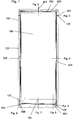
- Fig. 1 discloses a front elevation view of a plate 100 and a frame 102 according to the invention. As described in the aforementioned, the device will comprise two or more plates 100 which are provided such that any two neighbouring plates 100 are separated by a frame 102.
- An entry passage 201 for the distilling fluid a gutter shaped groove for spreading of the distilling fluid 203, a detachable drip nose 202, a vapour passage opening 301, a number of O-ring sealings 103, outlet openings 106 and 107, guiding means for assembly 601, the separator 105, the fixation mean for the separator 701, the outlet passage between the separator gutter and the outlet holes 801, a number of holes for compression means 104 and the drip catcher 401.
- Fig 2 discloses a cross section view of the distilling fluid entry 201 in form of a hose connection.
- the distilling fluid entry stretches into and through the frame 102 to the u-shaped gutter 203 that will enhance the spreading of the fluid over the width of the plate 100.
- the drip nose 202 is shown here as a detachable component stretching from one side to the other of the frame 102 or at least over the same distance as the gutter 203.
- the o-rings 103 on both sides of the frame 102 ensures the vapour and fluid tightness between frame 102 and plates 100.
- Fig 3 discloses a cross section of the vapour passage hole 301 in the frame 102 in a form where the vapour passes first through a sideways oriented hole that corresponds with a vertical hole in the frame 102. To avoid loss of vapour an o- ring 103 is placed to seal the vapour passage 301 to one another.
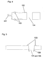
- Fig 4 discloses a cross section of a side of the frame 102 where a drip catcher 401 is placed in the inner side of the frame 102.
- the distillate that is collected in this drip catcher is lead to the upper side of the separator 105 so that the distillate runs off on the upper side of the separator.
- o-rings 103 ensures tightness between plates 100 and frame 102.
- Fig 5 discloses a cross section the identical outlet holes 106 and 107 for the first and second fluid flow. Tightness between frames in a stacked embodiment is ensured by o-rings 103. A combined drip nose and assembly guide is shown in 108 that interlock the frames 102 when being stacked.
- Fig 6 discloses a cross section of the lower end of the frame 102 with 2 plates 100, showing the moulded separator 105 that stretches from the one side of the frame to the other.
- Fig 7 discloses a cross section of the lower end of the frame 102 with 2 plates 100, showing the moulded separator 105 that stretches from the one side of the frame to the other and with a spacer 701 that holds the separator 105 in place between the plates 100.
- 104 is another hole for means of compression.
- Fig 8 shows a cross section of the lower end of the frame 102 with 2 plates 100, showing the fluid connection 801 between the gutter on one side of the separator 105 and the outlet hole 107 leading one of the fluid flow out.
- a similar fluid connection 801 is placed on the other side of the separator and corresponds to the other outlet hole 106 leading the other fluid flow out.
Landscapes
- Chemical & Material Sciences (AREA)
- Chemical Kinetics & Catalysis (AREA)
- Life Sciences & Earth Sciences (AREA)
- Hydrology & Water Resources (AREA)
- Engineering & Computer Science (AREA)
- Environmental & Geological Engineering (AREA)
- Water Supply & Treatment (AREA)
- Organic Chemistry (AREA)
- Vaporization, Distillation, Condensation, Sublimation, And Cold Traps (AREA)
- Heat Treatment Of Water, Waste Water Or Sewage (AREA)
Claims (9)
- Dispositif destiné à distiller un fluide, le dispositif comprenant :- une première et une deuxième plaques (100) ;- un cadre (102) avec des surfaces externes opposées, lesquelles peuvent être attachées de façon amovible à des surfaces internes des première et deuxième plaques (100), et présentant une forme suivant laquelle une chambre seulement est définie par le cadre et les surfaces internes, le cadre (102) définissant :- un orifice d'admission (201) pour amener le fluide dans la chambre,- un premier orifice de sortie (106) pour évacuer le fluide de rejet hors de la chambre,- un deuxième orifice de sortie (107) pour évacuer le fluide distillé hors de la chambre, et- un séparateur (105) ;
cas dans lequel l'orifice d'admission (201) est agencé de façon à permettre au fluide, qui est amené dans la chambre, de s'écouler suivant un premier trajet d'écoulement le long de la surface interne de la première plaque (100) à partir de l'orifice d'admission (201) jusqu'au premier orifice de sortie (106) ;
cas dans lequel le deuxième orifice de sortie (107) est agencé de façon à être en communication d'écoulement avec un deuxième trajet d'écoulement le long de la surface interne de la deuxième plaque (100) afin de capter le fluide qui est formé grâce à la condensation ayant lieu sur la surface interne de la deuxième plaque (100) ; et
cas dans lequel le séparateur (105) est défini par un élément essentiellement plat lequel est formé d'un seul tenant avec le cadre (102) et se prolonge à partir d'un emplacement situé entre les orifices de sortie (106, 107) suivant un sens allant vers l'orifice d'admission (201), et est agencé entre les surfaces externes afin de séparer une partie de la chambre en un premier espace, dans lequel se termine le premier trajet, et en un deuxième espace, dans lequel se termine le deuxième trajet d'écoulement ;
cas dans lequel ladite une chambre, définie entre les première et deuxième plaques (100), est une chambre combinée d'évaporation et de condensation, alors qu'une surface d'évaporation inférieure est définie par la surface interne de la première plaque (100), et qu'une surface de condensation supérieure est définie par la surface interne de la deuxième plaque (100) ;
cas dans lequel l'orifice d'admission est formé avec une rainure en forme de gouttière (20) laquelle s'étend dans le plan transversal par rapport au premier trajet d'écoulement, et est façonnée pour permettre au fluide entrant dans le dispositif à travers l'orifice d'amission d'être distribué sur une certaine largeur du cadre avant d'être amené sur la première surface, ladite rainure en forme de gouttière (203) et le cadre (102) définissant un élément monolithique ;
cas dans lequel un bec d'égouttage (202) est prévu au-dessus de la rainure en forme de gouttière (203), alors que le bec d'égouttage (202) définit une rainure en face de la rainure en forme de gouttière (203), par conséquent un conduit d'écoulement s'étendant dans le plan transversal est ainsi défini par la rainure en forme de gouttière (203) et ladite rainure opposée. - Dispositif selon la revendication 1, comprenant en outre un élément de régulation de flux lequel couvre au moins une partie de la rainure en forme de gouttière (203) et la première surface, l'élément de régulation de flux étant conçu pour piloter une vitesse de liquide coulant depuis l'orifice d'admission (201) vers le premier orifice de sortie (106) et/ou pour veiller à une distribution uniforme du liquide sur au moins une partie de la première surface.
- Dispositif selon l'une quelconque des revendications précédentes, le cadre sur au moins une de ses surfaces internes définissant un dispositif de récupération de gouttes (401) conçu pour collecter de l'eau distillée de sorte à éviter que ladite eau distillée ne coule du premier trajet d'écoulement vers le deuxième trajet d'écoulement le long de la surface interne du cadre (102).
- Dispositif selon l'une quelconque des revendications précédentes, le cadre (102) comprenant des moyens de guidage (601) pour guider l'opération de fixation des plaques sur le cadre.
- Dispositif selon l'une quelconque des revendications précédentes, comprenant une pluralité de cadres (102) lesquels sont agencés entre les plaques (100) afin de former une structure empilée avec une pluralité de chambres.
- Dispositif selon la revendication 5, comprenant un cadre supérieur (102) lequel forme une couche supérieure dans la structure empilée, et un cadre inférieur (102) lequel forme une couche inférieure dans la structure empilée, les cadres supérieur et inférieur (102) facilitant la fixation d'une structure de compression (104) destinée à comprimer toutes les couches de la structure empilée les unes vers les autres.
- Dispositif selon l'une quelconque des revendications précédentes, au moins l'une des plaques (100) définissant au moins un passage à vapeur (301) qui permet à la vapeur de passer à travers la plaque (100).
- Dispositif selon l'une quelconque des revendications précédentes, les plaques (100) étant fabriquées à partir d'une feuille de métal essentiellement plane.
- Dispositif selon l'une quelconque des revendications précédentes, les surfaces externes comprenant une structure d'étanchéisation (103) pour sceller fermement le fluide contre les surfaces internes lorsqu'elle est sollicitée contre celles-ci.
Applications Claiming Priority (2)
| Application Number | Priority Date | Filing Date | Title |
|---|---|---|---|
| DKPA200701698 | 2007-11-29 | ||
| PCT/DK2008/000378 WO2009068029A1 (fr) | 2007-11-29 | 2008-10-28 | Dispositif modulaire de distillation d'eau |
Publications (3)
| Publication Number | Publication Date |
|---|---|
| EP2220001A1 EP2220001A1 (fr) | 2010-08-25 |
| EP2220001A4 EP2220001A4 (fr) | 2011-12-14 |
| EP2220001B1 true EP2220001B1 (fr) | 2016-04-13 |
Family
ID=40678044
Family Applications (1)
| Application Number | Title | Priority Date | Filing Date |
|---|---|---|---|
| EP08854320.2A Not-in-force EP2220001B1 (fr) | 2007-11-29 | 2008-10-28 | Dispositif modulaire de distillation d'eau |
Country Status (3)
| Country | Link |
|---|---|
| EP (1) | EP2220001B1 (fr) |
| ES (1) | ES2582204T3 (fr) |
| WO (1) | WO2009068029A1 (fr) |
Families Citing this family (1)
| Publication number | Priority date | Publication date | Assignee | Title |
|---|---|---|---|---|
| EP2072100A1 (fr) | 2007-12-20 | 2009-06-24 | VKR Holding A/S | Module de distillation incliné multi-effet doté de moyens de chauffage et de refroidissement |
Family Cites Families (7)
| Publication number | Priority date | Publication date | Assignee | Title |
|---|---|---|---|---|
| SE390379B (sv) * | 1973-07-30 | 1976-12-20 | R Saari | Destillationsapparatur med flera steg |
| DE2346856A1 (de) | 1973-09-18 | 1975-03-27 | Wolfgang Ladewig | Sicherheitsschalter fuer fahrzeuge |
| GB2045626B (en) | 1979-03-22 | 1983-05-25 | Oriental Metal Seizo Co | Process and apparatus for the distillation of water |
| US4402793A (en) | 1980-02-19 | 1983-09-06 | Petrek John P | Multiple effect thin film distillation system and process |
| FR2583738B1 (fr) * | 1985-06-21 | 1990-12-14 | Centre Nat Rech Scient | Procede et dispositif de distillation, en particulier pour la preparation d'eau douce a partir de solutions salines. |
| JPH11156341A (ja) | 1997-11-26 | 1999-06-15 | Top Ecology:Kk | 太陽熱蒸留装置 |
| WO2006002636A1 (fr) * | 2004-07-06 | 2006-01-12 | Idekontoret Aps | Couche et module pour systeme de distillation a effet multiple |
-
2008
- 2008-10-28 ES ES08854320.2T patent/ES2582204T3/es active Active
- 2008-10-28 EP EP08854320.2A patent/EP2220001B1/fr not_active Not-in-force
- 2008-10-28 WO PCT/DK2008/000378 patent/WO2009068029A1/fr not_active Ceased
Also Published As
| Publication number | Publication date |
|---|---|
| EP2220001A1 (fr) | 2010-08-25 |
| EP2220001A4 (fr) | 2011-12-14 |
| ES2582204T3 (es) | 2016-09-09 |
| WO2009068029A1 (fr) | 2009-06-04 |
Similar Documents
| Publication | Publication Date | Title |
|---|---|---|
| EP2920539B1 (fr) | Ensemble de ventilation | |
| US7966841B2 (en) | Heat and mass exchanger | |
| US9770673B2 (en) | Apparatus for diffusion-gap thermal desalination | |
| AU2013208996C1 (en) | Cooling device | |
| EP3801800B1 (fr) | Appareil de distillation à membrane multiétages | |
| CN101251340A (zh) | 冷却塔空气入口和排放盘 | |
| GB1096678A (en) | Distillation method and apparatus | |
| TWI392842B (zh) | 回流凝結器 | |
| EP2220001B1 (fr) | Dispositif modulaire de distillation d'eau | |
| EP3801845B1 (fr) | Système d'écoulement modulaire à configuration de canal de vapeur et/ou de liquide améliorée | |
| CN113167551B (zh) | 用于处理诸如海水的进料的板式换热器和换热板 | |
| JP2010507775A5 (fr) | ||
| AU2010289019A1 (en) | Plate heat exchanger | |
| EP3801801B1 (fr) | Appareil de distillation à membrane pour produire de l'eau | |
| EP3801846B1 (fr) | Système d'écoulement modulaire avec éléments d'entretoise internes | |
| CN112638511B (zh) | 具有非对称或间断液体通路的模块化流系统 | |
| WO2006002636A1 (fr) | Couche et module pour systeme de distillation a effet multiple | |
| US20240219127A1 (en) | Heat exchanger with vapor extractors | |
| CN102794027A (zh) | 毛细管式油雾过滤装置 | |
| WO2005104860A2 (fr) | Applicateur de produit distille pour echangeurs thermiques plats |
Legal Events
| Date | Code | Title | Description |
|---|---|---|---|
| PUAI | Public reference made under article 153(3) epc to a published international application that has entered the european phase |
Free format text: ORIGINAL CODE: 0009012 |
|
| 17P | Request for examination filed |
Effective date: 20100629 |
|
| AK | Designated contracting states |
Kind code of ref document: A1 Designated state(s): AT BE BG CH CY CZ DE DK EE ES FI FR GB GR HR HU IE IS IT LI LT LU LV MC MT NL NO PL PT RO SE SI SK TR |
|
| AX | Request for extension of the european patent |
Extension state: AL BA MK RS |
|
| DAX | Request for extension of the european patent (deleted) | ||
| A4 | Supplementary search report drawn up and despatched |
Effective date: 20111116 |
|
| RIC1 | Information provided on ipc code assigned before grant |
Ipc: B01D 3/00 20060101ALI20111110BHEP Ipc: F28D 9/00 20060101ALI20111110BHEP Ipc: F28D 5/02 20060101ALI20111110BHEP Ipc: F28F 3/08 20060101ALI20111110BHEP Ipc: C02F 1/04 20060101AFI20111110BHEP Ipc: B01D 1/26 20060101ALI20111110BHEP Ipc: B01D 3/26 20060101ALI20111110BHEP Ipc: B01D 1/22 20060101ALI20111110BHEP |
|
| 17Q | First examination report despatched |
Effective date: 20121023 |
|
| GRAP | Despatch of communication of intention to grant a patent |
Free format text: ORIGINAL CODE: EPIDOSNIGR1 |
|
| RIC1 | Information provided on ipc code assigned before grant |
Ipc: B01D 21/26 20060101ALI20150903BHEP Ipc: B01D 3/00 20060101ALI20150903BHEP Ipc: F28D 1/03 20060101ALI20150903BHEP Ipc: B01D 1/22 20060101ALI20150903BHEP Ipc: F28D 5/02 20060101ALI20150903BHEP Ipc: F28F 3/10 20060101ALI20150903BHEP Ipc: C02F 1/04 20060101AFI20150903BHEP Ipc: B01D 3/26 20060101ALI20150903BHEP Ipc: F28D 9/00 20060101ALI20150903BHEP Ipc: F28F 3/08 20060101ALI20150903BHEP |
|
| INTG | Intention to grant announced |
Effective date: 20150928 |
|
| GRAS | Grant fee paid |
Free format text: ORIGINAL CODE: EPIDOSNIGR3 |
|
| RAP1 | Party data changed (applicant data changed or rights of an application transferred) |
Owner name: IDEKONTORET APS |
|
| RIN1 | Information on inventor provided before grant (corrected) |
Inventor name: ANDERSEN, TOM, JUUL |
|
| GRAA | (expected) grant |
Free format text: ORIGINAL CODE: 0009210 |
|
| AK | Designated contracting states |
Kind code of ref document: B1 Designated state(s): AT BE BG CH CY CZ DE DK EE ES FI FR GB GR HR HU IE IS IT LI LT LU LV MC MT NL NO PL PT RO SE SI SK TR |
|
| REG | Reference to a national code |
Ref country code: GB Ref legal event code: FG4D |
|
| REG | Reference to a national code |
Ref country code: AT Ref legal event code: REF Ref document number: 789930 Country of ref document: AT Kind code of ref document: T Effective date: 20160415 Ref country code: CH Ref legal event code: EP |
|
| REG | Reference to a national code |
Ref country code: IE Ref legal event code: FG4D |
|
| REG | Reference to a national code |
Ref country code: DE Ref legal event code: R096 Ref document number: 602008043630 Country of ref document: DE |
|
| REG | Reference to a national code |
Ref country code: LT Ref legal event code: MG4D |
|
| REG | Reference to a national code |
Ref country code: ES Ref legal event code: FG2A Ref document number: 2582204 Country of ref document: ES Kind code of ref document: T3 Effective date: 20160909 |
|
| REG | Reference to a national code |
Ref country code: AT Ref legal event code: MK05 Ref document number: 789930 Country of ref document: AT Kind code of ref document: T Effective date: 20160413 |
|
| REG | Reference to a national code |
Ref country code: FR Ref legal event code: PLFP Year of fee payment: 9 |
|
| REG | Reference to a national code |
Ref country code: NL Ref legal event code: MP Effective date: 20160413 |
|
| PG25 | Lapsed in a contracting state [announced via postgrant information from national office to epo] |
Ref country code: NL Free format text: LAPSE BECAUSE OF FAILURE TO SUBMIT A TRANSLATION OF THE DESCRIPTION OR TO PAY THE FEE WITHIN THE PRESCRIBED TIME-LIMIT Effective date: 20160413 Ref country code: PL Free format text: LAPSE BECAUSE OF FAILURE TO SUBMIT A TRANSLATION OF THE DESCRIPTION OR TO PAY THE FEE WITHIN THE PRESCRIBED TIME-LIMIT Effective date: 20160413 Ref country code: FI Free format text: LAPSE BECAUSE OF FAILURE TO SUBMIT A TRANSLATION OF THE DESCRIPTION OR TO PAY THE FEE WITHIN THE PRESCRIBED TIME-LIMIT Effective date: 20160413 Ref country code: NO Free format text: LAPSE BECAUSE OF FAILURE TO SUBMIT A TRANSLATION OF THE DESCRIPTION OR TO PAY THE FEE WITHIN THE PRESCRIBED TIME-LIMIT Effective date: 20160713 Ref country code: LT Free format text: LAPSE BECAUSE OF FAILURE TO SUBMIT A TRANSLATION OF THE DESCRIPTION OR TO PAY THE FEE WITHIN THE PRESCRIBED TIME-LIMIT Effective date: 20160413 |
|
| PG25 | Lapsed in a contracting state [announced via postgrant information from national office to epo] |
Ref country code: AT Free format text: LAPSE BECAUSE OF FAILURE TO SUBMIT A TRANSLATION OF THE DESCRIPTION OR TO PAY THE FEE WITHIN THE PRESCRIBED TIME-LIMIT Effective date: 20160413 Ref country code: LV Free format text: LAPSE BECAUSE OF FAILURE TO SUBMIT A TRANSLATION OF THE DESCRIPTION OR TO PAY THE FEE WITHIN THE PRESCRIBED TIME-LIMIT Effective date: 20160413 Ref country code: SE Free format text: LAPSE BECAUSE OF FAILURE TO SUBMIT A TRANSLATION OF THE DESCRIPTION OR TO PAY THE FEE WITHIN THE PRESCRIBED TIME-LIMIT Effective date: 20160413 Ref country code: PT Free format text: LAPSE BECAUSE OF FAILURE TO SUBMIT A TRANSLATION OF THE DESCRIPTION OR TO PAY THE FEE WITHIN THE PRESCRIBED TIME-LIMIT Effective date: 20160816 Ref country code: HR Free format text: LAPSE BECAUSE OF FAILURE TO SUBMIT A TRANSLATION OF THE DESCRIPTION OR TO PAY THE FEE WITHIN THE PRESCRIBED TIME-LIMIT Effective date: 20160413 |
|
| PG25 | Lapsed in a contracting state [announced via postgrant information from national office to epo] |
Ref country code: BE Free format text: LAPSE BECAUSE OF FAILURE TO SUBMIT A TRANSLATION OF THE DESCRIPTION OR TO PAY THE FEE WITHIN THE PRESCRIBED TIME-LIMIT Effective date: 20160413 |
|
| REG | Reference to a national code |
Ref country code: DE Ref legal event code: R097 Ref document number: 602008043630 Country of ref document: DE |
|
| PG25 | Lapsed in a contracting state [announced via postgrant information from national office to epo] |
Ref country code: DK Free format text: LAPSE BECAUSE OF FAILURE TO SUBMIT A TRANSLATION OF THE DESCRIPTION OR TO PAY THE FEE WITHIN THE PRESCRIBED TIME-LIMIT Effective date: 20160413 Ref country code: SK Free format text: LAPSE BECAUSE OF FAILURE TO SUBMIT A TRANSLATION OF THE DESCRIPTION OR TO PAY THE FEE WITHIN THE PRESCRIBED TIME-LIMIT Effective date: 20160413 Ref country code: EE Free format text: LAPSE BECAUSE OF FAILURE TO SUBMIT A TRANSLATION OF THE DESCRIPTION OR TO PAY THE FEE WITHIN THE PRESCRIBED TIME-LIMIT Effective date: 20160413 Ref country code: CZ Free format text: LAPSE BECAUSE OF FAILURE TO SUBMIT A TRANSLATION OF THE DESCRIPTION OR TO PAY THE FEE WITHIN THE PRESCRIBED TIME-LIMIT Effective date: 20160413 Ref country code: RO Free format text: LAPSE BECAUSE OF FAILURE TO SUBMIT A TRANSLATION OF THE DESCRIPTION OR TO PAY THE FEE WITHIN THE PRESCRIBED TIME-LIMIT Effective date: 20160413 |
|
| PGFP | Annual fee paid to national office [announced via postgrant information from national office to epo] |
Ref country code: DE Payment date: 20160915 Year of fee payment: 9 |
|
| REG | Reference to a national code |
Ref country code: GR Ref legal event code: EP Ref document number: 20160401615 Country of ref document: GR Effective date: 20161118 |
|
| PLBE | No opposition filed within time limit |
Free format text: ORIGINAL CODE: 0009261 |
|
| STAA | Information on the status of an ep patent application or granted ep patent |
Free format text: STATUS: NO OPPOSITION FILED WITHIN TIME LIMIT |
|
| 26N | No opposition filed |
Effective date: 20170116 |
|
| PG25 | Lapsed in a contracting state [announced via postgrant information from national office to epo] |
Ref country code: SI Free format text: LAPSE BECAUSE OF FAILURE TO SUBMIT A TRANSLATION OF THE DESCRIPTION OR TO PAY THE FEE WITHIN THE PRESCRIBED TIME-LIMIT Effective date: 20160413 |
|
| REG | Reference to a national code |
Ref country code: CH Ref legal event code: PL |
|
| GBPC | Gb: european patent ceased through non-payment of renewal fee |
Effective date: 20161028 |
|
| REG | Reference to a national code |
Ref country code: IE Ref legal event code: MM4A |
|
| PG25 | Lapsed in a contracting state [announced via postgrant information from national office to epo] |
Ref country code: LI Free format text: LAPSE BECAUSE OF NON-PAYMENT OF DUE FEES Effective date: 20161031 Ref country code: CH Free format text: LAPSE BECAUSE OF NON-PAYMENT OF DUE FEES Effective date: 20161031 Ref country code: GB Free format text: LAPSE BECAUSE OF NON-PAYMENT OF DUE FEES Effective date: 20161028 |
|
| PG25 | Lapsed in a contracting state [announced via postgrant information from national office to epo] |
Ref country code: LU Free format text: LAPSE BECAUSE OF NON-PAYMENT OF DUE FEES Effective date: 20161028 |
|
| REG | Reference to a national code |
Ref country code: FR Ref legal event code: PLFP Year of fee payment: 10 |
|
| PG25 | Lapsed in a contracting state [announced via postgrant information from national office to epo] |
Ref country code: IE Free format text: LAPSE BECAUSE OF NON-PAYMENT OF DUE FEES Effective date: 20161028 |
|
| REG | Reference to a national code |
Ref country code: DE Ref legal event code: R119 Ref document number: 602008043630 Country of ref document: DE |
|
| PG25 | Lapsed in a contracting state [announced via postgrant information from national office to epo] |
Ref country code: HU Free format text: LAPSE BECAUSE OF FAILURE TO SUBMIT A TRANSLATION OF THE DESCRIPTION OR TO PAY THE FEE WITHIN THE PRESCRIBED TIME-LIMIT; INVALID AB INITIO Effective date: 20081028 Ref country code: CY Free format text: LAPSE BECAUSE OF FAILURE TO SUBMIT A TRANSLATION OF THE DESCRIPTION OR TO PAY THE FEE WITHIN THE PRESCRIBED TIME-LIMIT Effective date: 20160413 |
|
| PG25 | Lapsed in a contracting state [announced via postgrant information from national office to epo] |
Ref country code: IS Free format text: LAPSE BECAUSE OF FAILURE TO SUBMIT A TRANSLATION OF THE DESCRIPTION OR TO PAY THE FEE WITHIN THE PRESCRIBED TIME-LIMIT Effective date: 20160413 Ref country code: MC Free format text: LAPSE BECAUSE OF FAILURE TO SUBMIT A TRANSLATION OF THE DESCRIPTION OR TO PAY THE FEE WITHIN THE PRESCRIBED TIME-LIMIT Effective date: 20160413 Ref country code: MT Free format text: LAPSE BECAUSE OF NON-PAYMENT OF DUE FEES Effective date: 20161031 |
|
| PG25 | Lapsed in a contracting state [announced via postgrant information from national office to epo] |
Ref country code: DE Free format text: LAPSE BECAUSE OF NON-PAYMENT OF DUE FEES Effective date: 20180501 Ref country code: BG Free format text: LAPSE BECAUSE OF FAILURE TO SUBMIT A TRANSLATION OF THE DESCRIPTION OR TO PAY THE FEE WITHIN THE PRESCRIBED TIME-LIMIT Effective date: 20160413 |
|
| REG | Reference to a national code |
Ref country code: FR Ref legal event code: PLFP Year of fee payment: 11 |
|
| PGFP | Annual fee paid to national office [announced via postgrant information from national office to epo] |
Ref country code: FR Payment date: 20180927 Year of fee payment: 11 |
|
| PGFP | Annual fee paid to national office [announced via postgrant information from national office to epo] |
Ref country code: TR Payment date: 20180928 Year of fee payment: 11 |
|
| PG25 | Lapsed in a contracting state [announced via postgrant information from national office to epo] |
Ref country code: FR Free format text: LAPSE BECAUSE OF NON-PAYMENT OF DUE FEES Effective date: 20191031 |
|
| PG25 | Lapsed in a contracting state [announced via postgrant information from national office to epo] |
Ref country code: TR Free format text: LAPSE BECAUSE OF NON-PAYMENT OF DUE FEES Effective date: 20191028 |
|
| PGFP | Annual fee paid to national office [announced via postgrant information from national office to epo] |
Ref country code: IT Payment date: 20221020 Year of fee payment: 15 Ref country code: ES Payment date: 20221102 Year of fee payment: 15 |
|
| PGFP | Annual fee paid to national office [announced via postgrant information from national office to epo] |
Ref country code: GR Payment date: 20221031 Year of fee payment: 15 |
|
| PG25 | Lapsed in a contracting state [announced via postgrant information from national office to epo] |
Ref country code: GR Free format text: LAPSE BECAUSE OF NON-PAYMENT OF DUE FEES Effective date: 20240515 |
|
| PG25 | Lapsed in a contracting state [announced via postgrant information from national office to epo] |
Ref country code: GR Free format text: LAPSE BECAUSE OF NON-PAYMENT OF DUE FEES Effective date: 20240515 |
|
| PG25 | Lapsed in a contracting state [announced via postgrant information from national office to epo] |
Ref country code: IT Free format text: LAPSE BECAUSE OF NON-PAYMENT OF DUE FEES Effective date: 20231028 |
|
| REG | Reference to a national code |
Ref country code: ES Ref legal event code: FD2A Effective date: 20241216 |
|
| PG25 | Lapsed in a contracting state [announced via postgrant information from national office to epo] |
Ref country code: IT Free format text: LAPSE BECAUSE OF NON-PAYMENT OF DUE FEES Effective date: 20231028 |
|
| PG25 | Lapsed in a contracting state [announced via postgrant information from national office to epo] |
Ref country code: ES Free format text: LAPSE BECAUSE OF NON-PAYMENT OF DUE FEES Effective date: 20231029 |
|
| PG25 | Lapsed in a contracting state [announced via postgrant information from national office to epo] |
Ref country code: ES Free format text: LAPSE BECAUSE OF NON-PAYMENT OF DUE FEES Effective date: 20231029 |