EP2221692A2 - Numerisch gesteuerte Werkzeugmaschine und numerische Steuervorrichtung - Google Patents
Numerisch gesteuerte Werkzeugmaschine und numerische Steuervorrichtung Download PDFInfo
- Publication number
- EP2221692A2 EP2221692A2 EP10004807A EP10004807A EP2221692A2 EP 2221692 A2 EP2221692 A2 EP 2221692A2 EP 10004807 A EP10004807 A EP 10004807A EP 10004807 A EP10004807 A EP 10004807A EP 2221692 A2 EP2221692 A2 EP 2221692A2
- Authority
- EP
- European Patent Office
- Prior art keywords
- error
- feed axis
- attitude
- axis
- command
- Prior art date
- Legal status (The legal status is an assumption and is not a legal conclusion. Google has not performed a legal analysis and makes no representation as to the accuracy of the status listed.)
- Granted
Links
Images







Classifications
-
- G—PHYSICS
- G05—CONTROLLING; REGULATING
- G05B—CONTROL OR REGULATING SYSTEMS IN GENERAL; FUNCTIONAL ELEMENTS OF SUCH SYSTEMS; MONITORING OR TESTING ARRANGEMENTS FOR SUCH SYSTEMS OR ELEMENTS
- G05B19/00—Program-control systems
- G05B19/02—Program-control systems electric
- G05B19/18—Numerical control [NC], i.e. automatically operating machines, in particular machine tools, e.g. in a manufacturing environment, so as to execute positioning, movement or co-ordinated operations by means of program data in numerical form
- G05B19/404—Numerical control [NC], i.e. automatically operating machines, in particular machine tools, e.g. in a manufacturing environment, so as to execute positioning, movement or co-ordinated operations by means of program data in numerical form characterised by control arrangements for compensation, e.g. for backlash, overshoot, tool offset, tool wear, temperature, machine construction errors, load, inertia
-
- B—PERFORMING OPERATIONS; TRANSPORTING
- B23—MACHINE TOOLS; METAL-WORKING NOT OTHERWISE PROVIDED FOR
- B23Q—DETAILS, COMPONENTS, OR ACCESSORIES FOR MACHINE TOOLS, e.g. ARRANGEMENTS FOR COPYING OR CONTROLLING; MACHINE TOOLS IN GENERAL CHARACTERISED BY THE CONSTRUCTION OF PARTICULAR DETAILS OR COMPONENTS; COMBINATIONS OR ASSOCIATIONS OF METAL-WORKING MACHINES, NOT DIRECTED TO A PARTICULAR RESULT
- B23Q17/00—Arrangements for observing, indicating or measuring on machine tools
- B23Q17/22—Arrangements for observing, indicating or measuring on machine tools for indicating or measuring existing or desired position of tool or work
-
- G—PHYSICS
- G05—CONTROLLING; REGULATING
- G05B—CONTROL OR REGULATING SYSTEMS IN GENERAL; FUNCTIONAL ELEMENTS OF SUCH SYSTEMS; MONITORING OR TESTING ARRANGEMENTS FOR SUCH SYSTEMS OR ELEMENTS
- G05B19/00—Program-control systems
- G05B19/02—Program-control systems electric
- G05B19/18—Numerical control [NC], i.e. automatically operating machines, in particular machine tools, e.g. in a manufacturing environment, so as to execute positioning, movement or co-ordinated operations by means of program data in numerical form
- G05B19/401—Numerical control [NC], i.e. automatically operating machines, in particular machine tools, e.g. in a manufacturing environment, so as to execute positioning, movement or co-ordinated operations by means of program data in numerical form characterised by control arrangements for measuring, e.g. calibration and initialisation, measuring workpiece for machining purposes
- G05B19/4015—Numerical control [NC], i.e. automatically operating machines, in particular machine tools, e.g. in a manufacturing environment, so as to execute positioning, movement or co-ordinated operations by means of program data in numerical form characterised by control arrangements for measuring, e.g. calibration and initialisation, measuring workpiece for machining purposes going to a reference at the beginning of machine cycle, e.g. for calibration
-
- G—PHYSICS
- G05—CONTROLLING; REGULATING
- G05B—CONTROL OR REGULATING SYSTEMS IN GENERAL; FUNCTIONAL ELEMENTS OF SUCH SYSTEMS; MONITORING OR TESTING ARRANGEMENTS FOR SUCH SYSTEMS OR ELEMENTS
- G05B2219/00—Program-control systems
- G05B2219/30—Nc systems
- G05B2219/33—Director till display
- G05B2219/33078—Error table, interpolate between two stored values to correct error
-
- G—PHYSICS
- G05—CONTROLLING; REGULATING
- G05B—CONTROL OR REGULATING SYSTEMS IN GENERAL; FUNCTIONAL ELEMENTS OF SUCH SYSTEMS; MONITORING OR TESTING ARRANGEMENTS FOR SUCH SYSTEMS OR ELEMENTS
- G05B2219/00—Program-control systems
- G05B2219/30—Nc systems
- G05B2219/37—Measurements
- G05B2219/37123—Extensible ball bar with potentiometer, lvdt
-
- G—PHYSICS
- G05—CONTROLLING; REGULATING
- G05B—CONTROL OR REGULATING SYSTEMS IN GENERAL; FUNCTIONAL ELEMENTS OF SUCH SYSTEMS; MONITORING OR TESTING ARRANGEMENTS FOR SUCH SYSTEMS OR ELEMENTS
- G05B2219/00—Program-control systems
- G05B2219/30—Nc systems
- G05B2219/39—Robotics, robotics to robotics hand
- G05B2219/39056—On line relative position error and orientation error calibration
-
- G—PHYSICS
- G05—CONTROLLING; REGULATING
- G05B—CONTROL OR REGULATING SYSTEMS IN GENERAL; FUNCTIONAL ELEMENTS OF SUCH SYSTEMS; MONITORING OR TESTING ARRANGEMENTS FOR SUCH SYSTEMS OR ELEMENTS
- G05B2219/00—Program-control systems
- G05B2219/30—Nc systems
- G05B2219/49—Nc machine tool, till multiple
- G05B2219/49344—Surface, 5-axis surface machining
-
- G—PHYSICS
- G05—CONTROLLING; REGULATING
- G05B—CONTROL OR REGULATING SYSTEMS IN GENERAL; FUNCTIONAL ELEMENTS OF SUCH SYSTEMS; MONITORING OR TESTING ARRANGEMENTS FOR SUCH SYSTEMS OR ELEMENTS
- G05B2219/00—Program-control systems
- G05B2219/30—Nc systems
- G05B2219/50—Machine tool, machine tool null till machine tool work handling
- G05B2219/50057—Compensation error by probing test, machined piece, post or pre process
-
- G—PHYSICS
- G05—CONTROLLING; REGULATING
- G05B—CONTROL OR REGULATING SYSTEMS IN GENERAL; FUNCTIONAL ELEMENTS OF SUCH SYSTEMS; MONITORING OR TESTING ARRANGEMENTS FOR SUCH SYSTEMS OR ELEMENTS
- G05B2219/00—Program-control systems
- G05B2219/30—Nc systems
- G05B2219/50—Machine tool, machine tool null till machine tool work handling
- G05B2219/50297—Compensation of positioning error due to a-axis, b-axis tool rotation
Definitions
- the present invention relates to a numerically controlled machine tool which has a linear feed axis and a rotational feed axis and in which a main spindle and a table are movable relative to each other.
- JP-2004-272887-A1 a method is disclosed in which, in a machine tool which has three linear feed axes (X, Y, Z) that are orthogonal to each other and two rotational feed axes (A, C) that are orthogonal to each other, the position to which the machine has to be actually moved is determined based on deviations of the center of a rotating shaft or the center of turning of a spindle, and by using drive control means, the linear feed axes and the rotational feed axes are moved to the determined position so as to correct the position of the tool tip.
- X, Y, Z linear feed axes
- A, C rotational feed axes
- JP-09-237112-A1 a method is disclosed in which an error of a tool unit of a machine tool having a parallel link mechanism is corrected based on an error map.
- the error map has error data corresponding to each lattice point that have been calculated by computation from the difference between the command value of a position and a posture for tool tip of the tool unit and the measured value of them.
- a system and a process for measuring, correcting and testing numerically controlled machine tool heads and/or tables are disclosed which are automated and integrated in a numerically controlled system.
- This system comprises at least one support base that is equipped with a plurality of distance sensors, and at least one device of gauge tool type that is equipped with connection means for the heads at one of its ends and with a ball at another opposite end.
- the ball is placed next to the distance sensors, so that the distance sensors are able, at any time and in any position, to move to any position in order to measure the distance that separates them from the ball, and to thereby determine the position in the Cartesian space.
- the present invention aims to resolve above-described problems associated with prior art, and therefore, it is an object of the present invention to provide a numerically controlled machine tool which has a linear feed axis and a rotational feed axis, and a numerically controlled machine tool having error map preparation function.
- a numerically controlled machine tool which has a linear feed axis and a rotational feed axis and which has functions of measuring in advance errors of a relative position and a relative attitude of a main spindle relative to a work table by positioning said linear feed axis and said rotational feed axis to specified position and attitude, and of correcting a movement command based on measured error data, said error data being multi-dimensional data containing a position error and an attitude error
- said machine tool comprising: a error data storage means which store an error map that is prepared by collecting a plurality of said error data corresponding to positions and rotation angles of said linear feed axis and said rotational feed axis, and a correction data computing means which compute correction data for correcting said movement command from a command position for said linear feed axis and said rotational feed axis and said error data stored in said error data storage means.
- the numerically controlled machine tool wherein said position error is an error of relative position of said main spindle relative to said work table, an error being expressed as 3-dimensional coordinate values when said rotational feed axis is positioned to specified rotation angle, and wherein said attitude error is an error of relative attitude of said main spindle relative to said work table, an error being expressed as inclination angle when a first rotational feed axis and a second rotational feed axis that are orthogonal to each other are positioned at specified rotation angles.
- the numerically controlled machine tool wherein a measurement spacing of said rotation angles in said first rotational feed axis and said second rotational feed axis is set such that a difference of said attitude error between adjoining measurement points is a specified value
- the numerically controlled machine tool wherein, when a tool tip position of a rotary tool mounted to said main spindle is to be positioned in accordance with said command position, said correction data computing means compute an amount of a deviation of 3-dimensional coordinate values of said tool tip position from said attitude error and a dimension of said rotary tool, and thereby correct said movement command for said linear feed axis
- a numerical control device which controls a machine tool having a linear feed axis and a rotational feed axis and which has a function of correcting movement command for feed axes based on error data that have been measured in advance, said device comprising: a error data storage means that store an error map prepared by collecting a plurality of said error data corresponding to a position and rotation angle of said feed axes, said error data being data containing a position error and an attitude error, and a correction data computing means which compute correction data for correcting said movement command from a command position for said feed axes and said error data stored in said error data storage means.
- an error map can be prepared by measuring the position error and the attitude error of the numerically controlled machine tool which has a linear feed axis and a rotational feed axis.
- error data for the position error and the attitude error that change as the feed axes are moved are stored separately, and the position command is corrected based on the error data. Therefore, in accordance with the present invention, even when the tool length or the tool projecting length varies, the tool tip or the processing point of the tool can be positioned to the target position with high precision.
- command position refers to the position of the destination point of the feed axis commanded by a processing program
- position command refers, from among the command pulses issued from the interpolation section to the servo section based on command position, command velocity, and the like, to the command for controlling the position of the feed axis.
- a numerically controlled machine tool comprises a numerical control device for controlling an operation of a machine in accordance with a processing program.
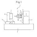
- Fig. 1 the construction of a five-axis horizontal type machining center having two rotational feed axes on the main spindle side, is shown.
- machining center 1 comprises bed 2 provided on the floor, column 3 that is erected on bed 2 and is capable of being moved linearly in a direction of Z-axis, and main spindle stock 5 that is capable of being moved linearly in a direction of Y-axis which is perpendicular to the direction of column 3.
- a bracket 5a is supported rotatably about C-axis which is parallel to Z-axis.
- main spindle head 4 is supported rotatably about A-axis which is parallel to X-axis.
- main spindle head 4 On main spindle head 4, a main spindle for holding a tool is rotatably supported.
- Machining center 1 is erected on bed 2 at a position opposed to main spindle head 4, and comprises table 6 that is capable of being moved linearly in a direction of X-axis which is perpendicular to the paper surface.
- work piece 7 is held via angle plate (equerre) 8 on table 6.
- Fig. 2 is a block diagram showing the construction of numerical control device 20 that controls the position of feed axes of the machine tool.
- Numerical control device 20 shown in Fig. 2 has the function of correcting position error and attitude error of the machine tool, and comprises reading and interpreting section 22 that reads and interprets processing program 21 to compute a command velocity and a command position for each feed axis, interpolating section 23 that computes command pulses based on the command position, command velocity, and the like to perform linear interpolation or circular interpolation of feed for each feed axis, position command recognition means 24 that obtains the command pulses and recognizes a position command for each feed axis, a computation section that computes a position error and an attitude error for a measurement point based on measurement data measured with measurement device 50 and the coordinates of the measurement point, error data storage means 25 that store the position error and the attitude error computed by the computation section in correspondence to the position of the linear feed axis and the rotation angle of the rotational feed axis, correction data computing section 26 that computes correction data for correcting the position command from the position command and the error data stored in error data storage means 25, correction pulse computation means 27 that
- Motor 30 for each feed axis is driven by the drive current which is amplified by servo section 29 to thereby move the feed axis.
- Servo section 29 controls based on the velocity feedback from motor 30 and the position feedback from an unshown position detecting device such that each feed axis is moved at desired velocity to desired position.
- the present invention also includes a device that is constructed such that the command position is obtained from reading and interpreting section 22 for correction, and the corrected command position is inputted into the interpolation section for the motor to move the machine to desired position.
- an error map As shown in Fig. 3 , lattice points 31 are set at desired positions in a direction of each axis of linear feed axes X, Y, Z in Cartesian coordinate system, and 2-dimensional array data 33 corresponding to the rotation angle of the rotational feed axes are associated with respective lattice points as shown in Fig. 4 .
- an error map is composed as 5-dimensional array data of X, Y, Z, A, C.
- An error map is composed of plural error data 34 obtained by measurement with each feed axis positioned at desired measurement points.
- Error data 34 are composed of position error 34a and attitude error 34b.
- Position error 34a refers to an error in relative position of the main spindle relative to the table, that is, an error of the position expressed as 3-dimensional coordinate value (x, y, z) produced when the feed axes are positioned at specified positions or rotation angles. That is, a position error is the difference between the theoretical position commanded by the position command and the actual position.
- Attitude error 34b refers to an error in relative attitude of the main spindle relative to the table, that is, an error expressed as inclination angles produced when the feed axes are positioned at specified positions or rotation angles.
- an attitude error is the difference between the theoretical inclination commanded by the position command and the actual inclination.
- Measurement spacing of error data 34 is set such that the difference of position error 34a or attitude error 34b between adjoining measurement points becomes equal to a specified value.
- the measurement spacing is broadened, and if the difference of error is large, the measurement spacing is narrowed.
- amount of data can be reduced and load on memory can be thereby reduced.
- narrowing the measurement spacing in the portion of large difference of error precision of the correction of error can be kept high.
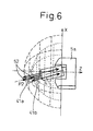
- measurement device 50 is mounted via support shaft 40 to the main spindle of the spindle rotation type machine tool, and comprises reference ball 52 which has known values of outer dimension and of distance L1, L2 from the control point to ball center P1, P2, and sensor bracket 53 which is mounted on palette 54 fixed to the table and has non-contact type sensors 55 in X-direction, Y-direction, Z-direction.
- the non-contact type sensor 55 can measure the distance to the reference ball 52 in each direction in non-contacting manner.
- the sensor of the present invention includes not only non-contact type sensor but also contact type sensor.
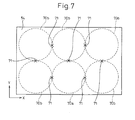
- Measurement is performed by dividing the measurement range of rotational feed axis A, C in even pitch or in uneven pitch, and operating, at the same time, the linear feed axis so as to maintain the center position of reference ball 52 at each division point (measurement point).
- even pitch means that a measurement point is defined at every specified angle so that an angular separation between adjoining measurement points is everywhere equal
- uneven pitch means that error data are obtained only at points where error exceeds a certain defined value so that an angular separation between adjoining measurement points is generally unequal.
- center position P1 of reference ball 52 is measured in directions X, Y, Z that are orthogonal to each other using measurement device 50 equipped with non-contact type sensors 55.
- the reference ball having support shaft 40 of different length is attached as shown in Fig. 6 , and center position P2 of reference ball 52 is measured again.
- support shafts 41a, 41b of different lengths for measurement By attaching support shafts 41a, 41b of different lengths for measurement, relative attitude of the main spindle and the table can be determined.
- the present invention includes the use of a support shaft whose length can be adjusted.
- the control point is set at the intersection point of the rotation center of first rotational feed axis C and the rotation center of second rotational feed axis A.
- relative attitude refers to the relative inclination of the main spindle and the table.
- Sensor bracket 53 of measurement device 50 is mounted rotatably about an axis that is parallel to Z-axis.
- the sensor bracket can be rotated about the axis that is parallel to Z-axis by 90 degrees four times to perform measurement.
- first measurement region 70a which is to be used as a reference
- operating ranges of linear feed axes X, Y, Z are measured with a laser gauge, an indicator, or the like, and adjustment is performed to obtain adequate precision as required.
- the present invention includes a case where adjustment of the precision of the operating ranges of linear feed axes X, Y, Z in first measurement region 70a is not performed, and error is computed taking into account the result of the measurement. This is intended to restrict the result of measurement in first measurement region 70a to the error produced when rotational feed axes A, C are rotated.
- the measurement points in measurement regions 70a, 70b are defined such that there exists at least one measurement points 71 having the same coordinate value of the linear feed axes as the measurement points in the adjoining measurement region. This is because an error in mounting measurement device 50 should not influence the result of measurement between first measurement region 70a and other measurement region 70b.
- the error in mounting measurement device 50 can be determined by subtracting the error due to difference of the rotation angle of the rotational feed axes from the difference of the result of measurement between measurement points having same coordinate value of the linear feed axes. By subtracting this error in mounting from the result of measurement in each measurement region, same result of measurement can be obtained as if all the measurement regions are measured in one proper arrangement.
- the attitude error is determined as follows. Commanded relative inclination of the main spindle relative to the table is determined from the command value of the rotation angles of rotational feed axes A, C.
- the angle formed by the rotation axis of the main spindle and the normal (perpendicular line) to the work piece attaching surface of the angle plate (equerre) is taken as the relative attitude of the main spindle and the table.
- attitude error is expressed by the angle difference i relative to Z-axis as seen from X-axis direction, the angle difference j relative to Z-axis as seen from Y-axis direction, and the angle difference k relative to Y-axis as seen from Z-axis direction.
- the present invention includes a case where, as shown in Fig. 10 , the attitude error is expressed by two angles I, J.
- the position error is determined as follows.
- the control point is set at the intersection point of the rotation center of first rotational feed axis C and the rotation center of second rotational feed axis A.
- the commanded position of the control point is determined from the command values of linear feed axes X, Y, Z.
- the position of the control point refers to the relative position of the reference point of the table relative to the control point of the main spindle.
- the position of a point at a distance L2 in the direction from P2 to P1 is determined and is taken as the actual position of the control point.
- a vector from the position of the commanded control point to the position of the actual control point is determined and is taken as the position error.
- the position error vector can be split into components in the direction of X-axis, Y-axis, Z-axis, and is expressed in the form of (x, y, z).
- the present invention includes a case where the position error vector is expressed in other form.
- Fig. 11 is a view showing an embodiment in which, in a spindle rotation type machine, reference ball 52 is attached to the side of palette 54 and displacement detection probe 58 is mounted on the spindle side. Displacement detection probe 58 is constructed such that it is displaced in a direction of the normal at the measurement point of the object to be measured, and the amount of the displacement is detected.
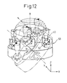
- Fig. 12 is a view showing an embodiment in which the present invention is applied to a table rotation type machine having rotational feed axes B, C on the table side.
- the error of the feed axes can be measured based on the same principle as in the embodiment shown in Fig. 5 .
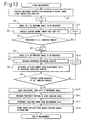
- Fig. 13 is a flow chart showing this measurement method.
- a test piece or a work piece is processed on the machine, and the processed test piece or work piece is measured with a touch probe mounted on the main spindle to thereby determine the position error and the attitude error.
- a cubic test piece is used in the present embodiment.
- rotational feed axes B, C are indexed to sufficiently small rotation angle (in this case, 0 degree for axis B, 0 degree for axis C) as required for sufficient precision of the position error and the attitude error, and as shown in Fig. 14 , each surface of test piece 60 (frame-like reference processing surface 61) having X, Y, Z-axis directions as the normal is processed without operating the rotational feed axes.
- reference processing surface 61 is frame-like is that the attitude error can be thereby accurately determined even when a large number of measurement points are used, and the attitude error can be determined more accurately by using the entire length of the test piece to measure the inclination.
- a ball end mill is used as cutting tool 63.
- Reference processing surface 61 is used as the reference for measuring the attitude error at a specified rotation angle of the rotational feed axes.
- the rotational feed axes are indexed to each measurement point, and three surfaces of the test piece that are orthogonal to each other are processed by operating only the linear feed axes.
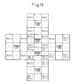
- a specified area is allotted as the area to be processed in accordance with the indexed angle of the rotational feed axis.
- the rotational feed axes are indexed to each measurement point, and P10-P14 of reference processing surface 61 are measured with touch probe 64, and actual inclination of the line passing through P10 and P11, actual inclination of the line passing through P10 and P12, and actual inclination of the line passing through P13 and P14 are determined. Difference between three inclinations thus determined and three theoretical inclinations computed from position command of the rotational feed axes at the time of measurement is taken as the attitude error.
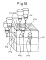
- the rotational feed axes are indexed to the reference rotation angle of 0 degree for B-axis and 0 degree for C-axis, and processed surface P15-P20 that are processed at each rotation angle are measured, and difference between the positions of processed surfaces P18-P20 that are processed with the rotational feed axis indexed to 0 degree for B-axis and 0 degree for C-axis and the positions of processed surfaces P15-P17 that are processed with the rotational feed axis indexed to other rotation angle is determined.
- the difference of positions and/or difference of inclinations between the processed surfaces that are processed at one rotation angle and the processed surfaces that are processed at other rotation angle are referred to as the displacement of the processed surfaces.
- intersection point P21 of three planes containing processed surfaces P18-P20 when it is assumed that there is no attitude error is determined.
- intersection point P22 of three planes containing processed surfaces P15-P17 is determined. Difference between intersection point P21 and intersection point P22 is taken as the position error.
- the present invention includes a case where a test piece or a work piece is processed with a machine tool having rotational feed axes on the main spindle side, and the position error and the attitude error are determined from measurement result of the processed surfaces.
- Error determined by the above-described method is associated with the positions of linear feed axes X, Y, Z and the rotation angles of rotational feed axes B, C, as shown in Fig. 4 , and is stored as an error map.
- the command position of processing program 21 is read by reading and interpreting section 22, and interpolation section 23 determines the command pulse for each of feed axes X, Y, Z, A, C for every specified interpolation period.
- position command recognition means 24 recognize from the command pulses the position command for each of feed axes X, Y, Z, A, C for every specified interpolation period.
- each feed axis in the position command is the same as the position of the measurement point stored in error data storage section 25, error data 34 are obtained, and correction data are determined based on the obtained error data. If the position of each feed axis in the position command is not the same as the position of the measurement point stored in error data storage section 25, the error data are obtained from the error data of nearby measurement point using known interpolation method, and correction data are determined based on the error data thus interpolated. Correction data thus determined are added to the position command to obtain new position command for every interpolation period. The position command is corrected in this manner, and each of the feed axes can be positioned with high precision.
- B-axis is an axis of a rotational feed axis that is parallel to Y-axis.
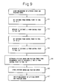
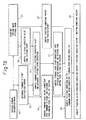
- Fig. 19 is a flow chart showing this correction method.
- step S0 the command position and the command attitude that are commanded by the position command outputted from interpolation section 23 are recognized.
- error data 34 corresponding to the command position are obtained from the error map.
- step S2 the position correction vector for correcting the position error is computed from position error 34a of error data 34.
- the attitude correction value is computed.
- the attitude correction value obtained at step S5 is added to the command attitude read out at step S3 to determine the attitude after correction.
- the command point after correction is determined.
- step S4 from the command attitude read out at step S3 and the projecting length of the tool, the command point before correction is determined.
- position correction vector of the command point for correcting the attitude error is computed by subtracting the command point before correction obtained at step S4 from the command point after correction obtained at step S7. This is referred to as the attitude correction vector.
- the attitude correction vector is a vector representing the magnitude and direction of the displacement of the tool tip when, with the basal end of the tool held by the main spindle as the control point, the rotational feed axes are rotated so as to correct the attitude error with the control point as the fulcrum.
- step S9 the attitude correction vector obtained at step S8 and the position correction vector obtained at step S2 are added.
- the command point refers to the position of the tool tip (tool tip position), and the tool tip position means the actual position of the tool tip, the position of the processing point of the tool tip portion, the center of the semi-sphere of the tip portion of a ball end mill, etc.
- the error of the tool tip position is corrected only by the movement of the linear feed axes, so that the rotational feed axes are not rotated during the correction of attitude error 34b, and the singular point problem can be circumvented.
- the position error and the attitude error of a machine tool having plural rotational feed axes can be measured and an error map can be prepared. Since, in the error map thus prepared, the position error and the attitude error are stored as separate error data, the position command can be corrected based on the error data, and the tool tip can be positioned to a target position with high precision to permit high precision processing.
- numerical control device 20 comprises a computation section that computes position error and the attitude error at the measurement points based on the measurement data obtained by measurement device 50 and the coordinate values of the measurement points, and error data storage means 25 for storing the position error and the attitude error computed by the computation section in correspondence to the position of the linear feed axes and the rotation angle of the rotational feed axes. It is also possible, in place of numerical control device 20 to use personal computer or other device for the computation section or the error data storage means.
Landscapes
- Engineering & Computer Science (AREA)
- Human Computer Interaction (AREA)
- Manufacturing & Machinery (AREA)
- Physics & Mathematics (AREA)
- General Physics & Mathematics (AREA)
- Automation & Control Theory (AREA)
- Mechanical Engineering (AREA)
- Numerical Control (AREA)
- Automatic Control Of Machine Tools (AREA)
- Machine Tool Sensing Apparatuses (AREA)
Priority Applications (1)
| Application Number | Priority Date | Filing Date | Title |
|---|---|---|---|
| EP10004807.3A EP2221692B1 (de) | 2007-11-02 | 2007-11-02 | Numerisch gesteuerte Werkzeugmaschine und numerische Steuervorrichtung |
Applications Claiming Priority (3)
| Application Number | Priority Date | Filing Date | Title |
|---|---|---|---|
| EP07831481.2A EP2208572B1 (de) | 2007-11-02 | 2007-11-02 | Verfahren und vorrichtung zur herstellung einer fehlertabelle und numerisch gesteuerte werkzeugmaschine mit einer fehlertabellenherstellungsfunktion |
| PCT/JP2007/071750 WO2009057229A1 (ja) | 2007-11-02 | 2007-11-02 | エラーマップ作成方法及び装置並びにエラーマップ作成機能を有した数値制御工作機械 |
| EP10004807.3A EP2221692B1 (de) | 2007-11-02 | 2007-11-02 | Numerisch gesteuerte Werkzeugmaschine und numerische Steuervorrichtung |
Related Parent Applications (3)
| Application Number | Title | Priority Date | Filing Date |
|---|---|---|---|
| EP07831481.2 Division | 2007-11-02 | ||
| EP07831481.2A Division EP2208572B1 (de) | 2007-11-02 | 2007-11-02 | Verfahren und vorrichtung zur herstellung einer fehlertabelle und numerisch gesteuerte werkzeugmaschine mit einer fehlertabellenherstellungsfunktion |
| EP07831481.2A Division-Into EP2208572B1 (de) | 2007-11-02 | 2007-11-02 | Verfahren und vorrichtung zur herstellung einer fehlertabelle und numerisch gesteuerte werkzeugmaschine mit einer fehlertabellenherstellungsfunktion |
Publications (3)
| Publication Number | Publication Date |
|---|---|
| EP2221692A2 true EP2221692A2 (de) | 2010-08-25 |
| EP2221692A3 EP2221692A3 (de) | 2013-10-09 |
| EP2221692B1 EP2221692B1 (de) | 2016-07-27 |
Family
ID=40590638
Family Applications (3)
| Application Number | Title | Priority Date | Filing Date |
|---|---|---|---|
| EP15002431.3A Active EP2975475B1 (de) | 2007-11-02 | 2007-11-02 | Verfahren zur herstellung einer fehlertabelle und numerisch gesteuerte werkzeugmaschine mit einer fehlertabellenherstellungsfunktion |
| EP10004807.3A Active EP2221692B1 (de) | 2007-11-02 | 2007-11-02 | Numerisch gesteuerte Werkzeugmaschine und numerische Steuervorrichtung |
| EP07831481.2A Active EP2208572B1 (de) | 2007-11-02 | 2007-11-02 | Verfahren und vorrichtung zur herstellung einer fehlertabelle und numerisch gesteuerte werkzeugmaschine mit einer fehlertabellenherstellungsfunktion |
Family Applications Before (1)
| Application Number | Title | Priority Date | Filing Date |
|---|---|---|---|
| EP15002431.3A Active EP2975475B1 (de) | 2007-11-02 | 2007-11-02 | Verfahren zur herstellung einer fehlertabelle und numerisch gesteuerte werkzeugmaschine mit einer fehlertabellenherstellungsfunktion |
Family Applications After (1)
| Application Number | Title | Priority Date | Filing Date |
|---|---|---|---|
| EP07831481.2A Active EP2208572B1 (de) | 2007-11-02 | 2007-11-02 | Verfahren und vorrichtung zur herstellung einer fehlertabelle und numerisch gesteuerte werkzeugmaschine mit einer fehlertabellenherstellungsfunktion |
Country Status (7)
| Country | Link |
|---|---|
| US (2) | US8786243B2 (de) |
| EP (3) | EP2975475B1 (de) |
| JP (1) | JP5058270B2 (de) |
| KR (2) | KR101158772B1 (de) |
| CN (1) | CN101842189B (de) |
| CA (1) | CA2704365C (de) |
| WO (1) | WO2009057229A1 (de) |
Cited By (3)
| Publication number | Priority date | Publication date | Assignee | Title |
|---|---|---|---|---|
| CN102759900A (zh) * | 2012-06-29 | 2012-10-31 | 上海三一精机有限公司 | 一种机床主轴热误差的测试系统及测试方法 |
| EP2541353A4 (de) * | 2010-02-25 | 2013-07-03 | Mitsubishi Electric Corp | Numerische steuerung |
| CN114234877A (zh) * | 2022-02-28 | 2022-03-25 | 成都飞机工业(集团)有限责任公司 | 一种用于R-test仪器的位移传感器矢量标定方法 |
Families Citing this family (65)
| Publication number | Priority date | Publication date | Assignee | Title |
|---|---|---|---|---|
| WO2010109536A1 (ja) * | 2009-03-27 | 2010-09-30 | 三菱電機株式会社 | 数値制御装置および当該数値制御装置の制御方法 |
| JP5293389B2 (ja) * | 2009-05-07 | 2013-09-18 | 株式会社ジェイテクト | 工作機械の制御装置 |
| WO2011010397A1 (ja) * | 2009-07-22 | 2011-01-27 | 株式会社牧野フライス製作所 | 誤差補正方法及び工作機械 |
| JP5471159B2 (ja) * | 2009-08-24 | 2014-04-16 | 株式会社ジェイテクト | 工作機械の制御装置 |
| JP4676549B2 (ja) * | 2009-09-10 | 2011-04-27 | ファナック株式会社 | 軌跡表示装置及び該軌跡表示装置を備えた工作機械 |
| JP2011152613A (ja) * | 2010-01-27 | 2011-08-11 | Okuma Corp | 多軸工作機械の加工精度確認方法及び加工精度確認用加工物 |
| DE102010029429A1 (de) * | 2010-05-28 | 2011-12-01 | Dr. Johannes Heidenhain Gmbh | Messvorrichtung |
| JP5014471B2 (ja) | 2010-06-30 | 2012-08-29 | ファナック株式会社 | 多軸加工機用数値制御装置 |
| US9477218B2 (en) * | 2010-10-27 | 2016-10-25 | Makino Milling Machine Co., Ltd. | Numerical control method and numerical control device of machine tool |
| JP2011173234A (ja) * | 2011-01-15 | 2011-09-08 | Ken Kobayashi | 工作機械の制御方法 |
| CN103328155B (zh) * | 2011-01-26 | 2016-06-15 | 三菱电机株式会社 | 误差显示装置及误差显示方法 |
| US8676373B2 (en) * | 2011-02-23 | 2014-03-18 | GM Global Technology Operations LLC | Global offset compensation for a CNC machine |
| CN102789197B (zh) * | 2011-05-19 | 2016-06-22 | 科德数控股份有限公司 | 数控机床加工信息的表达系统及其表达方法 |
| CN102501137B (zh) * | 2011-11-03 | 2014-01-15 | 西安交通大学 | 一种主轴径向回转精度在线监测装置 |
| CN103128521B (zh) * | 2011-11-22 | 2015-02-18 | 成都飞机工业(集团)有限责任公司 | 一种确定零件加工基准的方法及专用工具球 |
| KR20130086773A (ko) * | 2012-01-26 | 2013-08-05 | 두산인프라코어 주식회사 | 비전 기반 공작물 셋업 방법 |
| JP5852467B2 (ja) * | 2012-02-23 | 2016-02-03 | オークマ株式会社 | 数値制御装置 |
| US9573202B2 (en) * | 2012-03-30 | 2017-02-21 | Makino Milling Machine Co., Ltd. | Workpiece machining method, machine tool, tool path-generating device and tool path-generating program |
| ES2769304T3 (es) * | 2012-04-05 | 2020-06-25 | Fidia Spa | Dispositivo para corrección de errores para máquinas CNC |
| CN102744648B (zh) * | 2012-06-19 | 2014-06-25 | 西安瑞特快速制造工程研究有限公司 | 一种数控机床回转工作台误差测量与分离的方法 |
| JP5915436B2 (ja) * | 2012-07-27 | 2016-05-11 | ブラザー工業株式会社 | 数値制御装置とピッチ誤差算出方法 |
| EP2907621B1 (de) * | 2012-10-11 | 2019-12-04 | Makino Milling Machine Co., Ltd. | Werkzeugwegerzeugungsverfahren, verfahren zur steuerung einer werkzeugmaschine und werkzeugwegerzeugungsvorrichtung |
| WO2014068675A1 (ja) * | 2012-10-30 | 2014-05-08 | 株式会社牧野フライス製作所 | 工作機械の制御装置および工作機械 |
| EP2916184B1 (de) * | 2012-10-30 | 2019-01-02 | Makino Milling Machine Co., Ltd. | Vorrichtung zur ausgabe von informationen über eine werkstückbefestigung |
| US9222769B2 (en) | 2012-12-08 | 2015-12-29 | Grale Technologies | High speed metrology with numerically controlled machines |
| JP2014238782A (ja) * | 2013-06-10 | 2014-12-18 | オークマ株式会社 | 工作機械の制御方法 |
| JP5746270B2 (ja) | 2013-06-20 | 2015-07-08 | ファナック株式会社 | 穴あけ加工を行う工作機械の数値制御装置 |
| JP5792251B2 (ja) * | 2013-09-27 | 2015-10-07 | ファナック株式会社 | 誤差補正量作成装置 |
| JP5941083B2 (ja) * | 2014-03-12 | 2016-06-29 | ファナック株式会社 | 外部環境との接触を検知するロボット制御装置 |
| JP6184363B2 (ja) * | 2014-03-31 | 2017-08-23 | オークマ株式会社 | 工作機械の制御方法及び制御装置 |
| JP2016083729A (ja) * | 2014-10-27 | 2016-05-19 | オークマ株式会社 | 幾何誤差同定システム、及び幾何誤差同定方法 |
| JP2016155185A (ja) * | 2015-02-23 | 2016-09-01 | オークマ株式会社 | 工作機械の誤差同定方法 |
| JP6595273B2 (ja) * | 2015-09-11 | 2019-10-23 | Dmg森精機株式会社 | 数値制御装置 |
| US10203682B2 (en) | 2016-06-14 | 2019-02-12 | Doosan Machine Tools Co., Ltd. | Position controller for controlling a rotation center of a tilting head |
| WO2018092243A1 (ja) * | 2016-11-17 | 2018-05-24 | 株式会社Fuji | 作業位置補正方法および作業ロボット |
| WO2018092236A1 (ja) * | 2016-11-17 | 2018-05-24 | 株式会社Fuji | 作業ロボットおよび作業位置補正方法 |
| EP3327524B1 (de) | 2016-11-29 | 2023-04-05 | GF Machining Solutions AG | Kinematische kalibrierung |
| US10940586B2 (en) * | 2016-12-13 | 2021-03-09 | Fuji Corporation | Method for correcting target position of work robot |
| JP6484261B2 (ja) * | 2017-01-19 | 2019-03-13 | ファナック株式会社 | 数値制御装置 |
| US10050008B1 (en) * | 2017-01-24 | 2018-08-14 | Asm Technology Singapore Pte Ltd | Method and system for automatic bond arm alignment |
| JP6496338B2 (ja) | 2017-03-14 | 2019-04-03 | ファナック株式会社 | 工作機械の制御システム |
| JP6474450B2 (ja) | 2017-04-17 | 2019-02-27 | ファナック株式会社 | 工作機械の制御システム |
| JP6514264B2 (ja) * | 2017-04-20 | 2019-05-15 | ファナック株式会社 | 工作機械の制御システム |
| JP7035727B2 (ja) * | 2018-03-30 | 2022-03-15 | 日本電産株式会社 | キャリブレーション精度の評価方法及び評価装置 |
| IT201800007230A1 (it) * | 2018-07-16 | 2020-01-16 | Macchina utensile a controllo numerico | |
| JP6823024B2 (ja) * | 2018-09-11 | 2021-01-27 | ファナック株式会社 | ロボットのキャリブレーションシステムおよびキャリブレーション方法 |
| CN109333156B (zh) * | 2018-11-12 | 2019-11-26 | 电子科技大学 | 一种用于五轴数控机床rtcp检测的误差与姿态同步标定方法 |
| CN109781042B (zh) * | 2018-12-21 | 2021-01-19 | 西安交通大学 | 一种主轴回转误差测量装置 |
| JP7021130B2 (ja) * | 2019-01-16 | 2022-02-16 | ファナック株式会社 | モータ内の巻線の層間短絡を検出する短絡検出装置、モータ制御装置及び数値制御システム |
| DE102019110508A1 (de) * | 2019-04-23 | 2020-10-29 | Carl Zeiss Industrielle Messtechnik Gmbh | Verfahren zum Steuern eines Koordinatenmessgerätes und Koordinatenmessgerät |
| CN111890123B (zh) * | 2019-05-06 | 2022-02-08 | 四川大学 | 一种刀具前刀面轴向倾角在机检测计算方法 |
| IT201900012681A1 (it) | 2019-07-23 | 2021-01-23 | Parpas S P A | Metodo di funzionamento di una macchina utensile a controllo numerico e dispositivo di rilevamento per implementare tale metodo |
| US11487268B2 (en) * | 2019-07-25 | 2022-11-01 | Pratt & Whitney Canada Corp. | Method of calibrating a machine having at least two rotation axes |
| JP7192758B2 (ja) * | 2019-12-23 | 2022-12-20 | 株式会社ニコン | 加工装置および加工方法 |
| JP7026718B2 (ja) * | 2020-04-10 | 2022-02-28 | 株式会社牧野フライス製作所 | 加工方法 |
| JP6959389B2 (ja) * | 2020-04-15 | 2021-11-02 | 株式会社ソディック | 多軸加工機、多軸加工機の回転中心測定方法およびプログラム |
| US12517489B2 (en) * | 2020-07-10 | 2026-01-06 | Fanuc Corporation | Control device and control method for machine tool, and slave shaft control device |
| WO2022067594A1 (zh) * | 2020-09-30 | 2022-04-07 | 成都飞机工业(集团)有限责任公司 | 五轴联动数控机床旋转轴线位置误差检测方法及检测装置 |
| JP7558776B2 (ja) * | 2020-12-01 | 2024-10-01 | 株式会社日立製作所 | 計算機、パラメータ推定処理方法、及びパラメータ推定処理プログラム |
| CN112526927B (zh) * | 2021-02-18 | 2021-06-08 | 成都飞机工业(集团)有限责任公司 | 面向五轴数控机床旋转轴空间定位误差快速优化补偿方法 |
| JPWO2022202591A1 (de) * | 2021-03-23 | 2022-09-29 | ||
| JP7128333B1 (ja) * | 2021-08-24 | 2022-08-30 | 株式会社ソディック | 多軸加工機および多軸加工機の回転中心測定方法 |
| CN117245555A (zh) * | 2023-08-04 | 2023-12-19 | 天津大学 | 精密立式磨床热致主轴-转台轴线偏差测量装置与方法 |
| CN117681055A (zh) * | 2024-01-22 | 2024-03-12 | 北京发那科机电有限公司 | 机床调试方法、装置及机床 |
| CN119247877B (zh) * | 2024-09-13 | 2025-08-01 | 济宁博硕工具有限公司 | 一种刀具点空间位姿控制方法及刀具运动控制装置 |
Citations (4)
| Publication number | Priority date | Publication date | Assignee | Title |
|---|---|---|---|---|
| JPH0688192B2 (ja) | 1989-04-21 | 1994-11-09 | 株式会社牧野フライス製作所 | 5軸nc工作機械 |
| JPH09237112A (ja) | 1996-02-29 | 1997-09-09 | Toyoda Mach Works Ltd | 誤差補正機能を備えた工作機械 |
| WO2004034164A1 (en) | 2002-10-11 | 2004-04-22 | Fidia S.P.A. | System and process for measuring, compensating and testing numerically controlled machine tool heads and/or tables |
| JP2004272887A (ja) | 2003-02-19 | 2004-09-30 | Fanuc Ltd | 数値制御装置及び数値制御方法 |
Family Cites Families (26)
| Publication number | Priority date | Publication date | Assignee | Title |
|---|---|---|---|---|
| JPH0348903A (ja) | 1989-07-17 | 1991-03-01 | Ishikawa Pref Gov | 数値制御装置 |
| US5257460A (en) * | 1991-06-18 | 1993-11-02 | Renishaw Metrology Limited | Machine tool measurement methods |
| JPH0688192A (ja) * | 1991-08-28 | 1994-03-29 | Nisshin Steel Co Ltd | 加工性に優れた合金化溶融亜鉛めっき鋼板及びその製造方法 |
| CA2082790A1 (en) | 1991-12-02 | 1993-06-03 | R. David Hemmerle | Automated maintenance system for computer numerically controlled machines |
| JPH06332524A (ja) * | 1993-05-20 | 1994-12-02 | Fanuc Ltd | 数値制御装置における速度制御方法 |
| JP3174704B2 (ja) | 1994-11-29 | 2001-06-11 | ファナック株式会社 | 位置誤差補正機能付き数値制御装置 |
| JPH0922311A (ja) * | 1995-07-05 | 1997-01-21 | Fanuc Ltd | Cncの円弧加工制御方式 |
| IT1303170B1 (it) | 1998-07-10 | 2000-10-30 | Fidia Spa | Procedimento e sistema per la realizzazione della compensazione deglierrori statici su macchine utensili a controllo numerico |
| DE19858154B4 (de) | 1998-12-16 | 2008-01-24 | Fraunhofer-Gesellschaft zur Förderung der angewandten Forschung e.V. | Verfahren und Einrichtung zur Kalibrierung von bewegbaren Vorrichtungen mit mindestens einem teilweise unbestimmten Geometrieparameter |
| ATE253754T1 (de) | 1999-01-15 | 2003-11-15 | Harmony Software Inc | Verfahren und apparat zum verarbeiten von geschäftsinformationen aus mehreren unternehmen |
| JP4034906B2 (ja) * | 1999-04-27 | 2008-01-16 | 株式会社ミツトヨ | 表面性状測定機 |
| JP2001142515A (ja) * | 1999-11-18 | 2001-05-25 | Tomikazu Kamiya | 切削シミュレーション方法 |
| DE10046092A1 (de) * | 2000-09-18 | 2002-04-11 | Siemens Ag | Verfahren zur Kompensation von statischen Positionsfehlern und Orientierungsfehlern |
| JP2003121134A (ja) | 2001-10-16 | 2003-04-23 | Canon Inc | 運動精度の測定方法 |
| US7245982B2 (en) * | 2002-10-11 | 2007-07-17 | Fidia S.P.A. | System and process for measuring, compensating and testing numerically controlled machine tool heads and/or tables |
| US7283889B2 (en) * | 2003-02-19 | 2007-10-16 | Fanuc Ltd | Numerical control device, and numerical control method |
| JP4066906B2 (ja) * | 2003-08-08 | 2008-03-26 | 株式会社ジェイテクト | 数値制御装置及びncデータ作成装置 |
| JP3977302B2 (ja) * | 2003-08-13 | 2007-09-19 | キヤノン株式会社 | 露光装置及びその使用方法並びにデバイス製造方法 |
| CN1258431C (zh) * | 2004-03-31 | 2006-06-07 | 清华大学 | 数控机床误差补偿方法及其系统 |
| JP4609015B2 (ja) | 2004-09-21 | 2011-01-12 | セイコーエプソン株式会社 | 走査光学系、画像表示装置及び電子機器 |
| JP4290639B2 (ja) * | 2004-12-01 | 2009-07-08 | 三菱電機株式会社 | 数値制御装置及び数値制御工作機械 |
| JP2006289524A (ja) * | 2005-04-06 | 2006-10-26 | Fanuc Ltd | 加工物設置誤差測定装置 |
| JP2007034986A (ja) | 2005-07-29 | 2007-02-08 | Seiko Epson Corp | 特許情報管理システム、特許情報管理方法、プログラム、及び記録媒体 |
| GB0525306D0 (en) * | 2005-12-13 | 2006-01-18 | Renishaw Plc | Method of machine tool calibration |
| JP4510755B2 (ja) * | 2005-12-21 | 2010-07-28 | 株式会社牧野フライス製作所 | 工具刃先位置演算方法及び工作機械 |
| JP5280665B2 (ja) * | 2007-10-26 | 2013-09-04 | オークマ株式会社 | 手動シフト操作機能を備えた数値制御装置 |
-
2007
- 2007-11-02 WO PCT/JP2007/071750 patent/WO2009057229A1/ja not_active Ceased
- 2007-11-02 EP EP15002431.3A patent/EP2975475B1/de active Active
- 2007-11-02 JP JP2009538903A patent/JP5058270B2/ja active Active
- 2007-11-02 EP EP10004807.3A patent/EP2221692B1/de active Active
- 2007-11-02 KR KR1020107008406A patent/KR101158772B1/ko active Active
- 2007-11-02 CA CA2704365A patent/CA2704365C/en active Active
- 2007-11-02 EP EP07831481.2A patent/EP2208572B1/de active Active
- 2007-11-02 KR KR1020107008254A patent/KR101088843B1/ko active Active
- 2007-11-02 CN CN2007801014014A patent/CN101842189B/zh active Active
- 2007-11-02 US US12/740,126 patent/US8786243B2/en active Active
-
2010
- 2010-04-29 US US12/769,939 patent/US8680806B2/en active Active
Patent Citations (4)
| Publication number | Priority date | Publication date | Assignee | Title |
|---|---|---|---|---|
| JPH0688192B2 (ja) | 1989-04-21 | 1994-11-09 | 株式会社牧野フライス製作所 | 5軸nc工作機械 |
| JPH09237112A (ja) | 1996-02-29 | 1997-09-09 | Toyoda Mach Works Ltd | 誤差補正機能を備えた工作機械 |
| WO2004034164A1 (en) | 2002-10-11 | 2004-04-22 | Fidia S.P.A. | System and process for measuring, compensating and testing numerically controlled machine tool heads and/or tables |
| JP2004272887A (ja) | 2003-02-19 | 2004-09-30 | Fanuc Ltd | 数値制御装置及び数値制御方法 |
Cited By (5)
| Publication number | Priority date | Publication date | Assignee | Title |
|---|---|---|---|---|
| EP2541353A4 (de) * | 2010-02-25 | 2013-07-03 | Mitsubishi Electric Corp | Numerische steuerung |
| CN102759900A (zh) * | 2012-06-29 | 2012-10-31 | 上海三一精机有限公司 | 一种机床主轴热误差的测试系统及测试方法 |
| CN102759900B (zh) * | 2012-06-29 | 2014-11-05 | 上海三一精机有限公司 | 一种机床主轴热误差的测试系统及测试方法 |
| CN114234877A (zh) * | 2022-02-28 | 2022-03-25 | 成都飞机工业(集团)有限责任公司 | 一种用于R-test仪器的位移传感器矢量标定方法 |
| CN114234877B (zh) * | 2022-02-28 | 2022-06-14 | 成都飞机工业(集团)有限责任公司 | 一种用于R-test仪器的位移传感器矢量标定方法 |
Also Published As
| Publication number | Publication date |
|---|---|
| KR20100054864A (ko) | 2010-05-25 |
| EP2975475B1 (de) | 2019-05-08 |
| US20100244762A1 (en) | 2010-09-30 |
| EP2975475A1 (de) | 2016-01-20 |
| CA2704365A1 (en) | 2009-05-07 |
| CA2704365C (en) | 2015-05-05 |
| EP2221692B1 (de) | 2016-07-27 |
| KR101088843B1 (ko) | 2011-12-06 |
| US20100207567A1 (en) | 2010-08-19 |
| EP2221692A3 (de) | 2013-10-09 |
| US8786243B2 (en) | 2014-07-22 |
| KR20100047906A (ko) | 2010-05-10 |
| JPWO2009057229A1 (ja) | 2011-03-10 |
| US8680806B2 (en) | 2014-03-25 |
| KR101158772B1 (ko) | 2012-06-22 |
| WO2009057229A1 (ja) | 2009-05-07 |
| CN101842189A (zh) | 2010-09-22 |
| EP2208572B1 (de) | 2016-09-07 |
| EP2208572A1 (de) | 2010-07-21 |
| JP5058270B2 (ja) | 2012-10-24 |
| EP2208572A4 (de) | 2013-10-09 |
| CN101842189B (zh) | 2011-11-16 |
Similar Documents
| Publication | Publication Date | Title |
|---|---|---|
| EP2221692B1 (de) | Numerisch gesteuerte Werkzeugmaschine und numerische Steuervorrichtung | |
| CN101866163B (zh) | 数值控制机床及数值控制装置 | |
| EP0275428B2 (de) | Kalibrierungsverfahren für ein Koordinatenmessgerät und ähnliche Geräte | |
| JP5030653B2 (ja) | 数値制御工作機械及び数値制御装置 | |
| US4945501A (en) | Method for determining position within the measuring volume of a coordinate measuring machine and the like and system therefor | |
| US10209107B2 (en) | Geometric error identification method of multi-axis machine tool and multi-axis machine tool | |
| JP2021088024A (ja) | 数値制御装置、及び制御方法 | |
| US20030069709A1 (en) | Method for calibrating scanning probe and computer-readable medium therefor | |
| JP5355037B2 (ja) | 精度測定方法及び数値制御工作機械の誤差補正方法並びに誤差補正機能を有した数値制御工作機械 | |
| JP5963792B2 (ja) | エラーマップ作成方法及び装置並びにエラーマップ作成機能を有した数値制御工作機械 | |
| JP5956952B2 (ja) | 数値制御工作機械 | |
| JP2012104153A (ja) | エラーマップ作成方法及び装置並びにエラーマップ作成機能を有した数値制御工作機械 | |
| EP2085739B1 (de) | Verfahren zur Messung der Sondengeradheit | |
| EP0279926B1 (de) | Positionsbestimmungsverfahren innerhalb des Messraumes eines Koordinatenmessgerätes und dergleichen und System dafür | |
| JP2016154039A (ja) | エラーマップ作成方法及び装置並びにエラーマップ作成機能を有した数値制御工作機械 | |
| CA2717291C (en) | Numerically controlled machine tool and numerical control device | |
| JP4618616B2 (ja) | 数値制御装置 | |
| JP2012079358A (ja) | エラーマップ作成方法及び装置並びにエラーマップ作成機能を有した数値制御工作機械 | |
| JP2012033203A (ja) | 数値制御工作機械 |
Legal Events
| Date | Code | Title | Description |
|---|---|---|---|
| PUAI | Public reference made under article 153(3) epc to a published international application that has entered the european phase |
Free format text: ORIGINAL CODE: 0009012 |
|
| 17P | Request for examination filed |
Effective date: 20100506 |
|
| AC | Divisional application: reference to earlier application |
Ref document number: 2208572 Country of ref document: EP Kind code of ref document: P |
|
| AK | Designated contracting states |
Kind code of ref document: A2 Designated state(s): AT BE BG CH CY CZ DE DK EE ES FI FR GB GR HU IE IS IT LI LT LU LV MC MT NL PL PT RO SE SI SK TR |
|
| AX | Request for extension of the european patent |
Extension state: AL BA HR MK RS |
|
| PUAL | Search report despatched |
Free format text: ORIGINAL CODE: 0009013 |
|
| AK | Designated contracting states |
Kind code of ref document: A3 Designated state(s): AT BE BG CH CY CZ DE DK EE ES FI FR GB GR HU IE IS IT LI LT LU LV MC MT NL PL PT RO SE SI SK TR |
|
| AX | Request for extension of the european patent |
Extension state: AL BA HR MK RS |
|
| RIC1 | Information provided on ipc code assigned before grant |
Ipc: B23Q 17/22 20060101ALI20130904BHEP Ipc: G05B 19/404 20060101ALI20130904BHEP Ipc: G05B 19/401 20060101AFI20130904BHEP |
|
| REG | Reference to a national code |
Ref country code: DE Ref legal event code: R079 Ref document number: 602007047233 Country of ref document: DE Free format text: PREVIOUS MAIN CLASS: G05B0019404000 Ipc: G05B0019401000 |
|
| RIC1 | Information provided on ipc code assigned before grant |
Ipc: B23Q 17/22 20060101ALI20140528BHEP Ipc: G05B 19/401 20060101AFI20140528BHEP Ipc: G05B 19/404 20060101ALI20140528BHEP |
|
| 17Q | First examination report despatched |
Effective date: 20140612 |
|
| GRAP | Despatch of communication of intention to grant a patent |
Free format text: ORIGINAL CODE: EPIDOSNIGR1 |
|
| INTG | Intention to grant announced |
Effective date: 20160222 |
|
| GRAS | Grant fee paid |
Free format text: ORIGINAL CODE: EPIDOSNIGR3 |
|
| GRAA | (expected) grant |
Free format text: ORIGINAL CODE: 0009210 |
|
| AC | Divisional application: reference to earlier application |
Ref document number: 2208572 Country of ref document: EP Kind code of ref document: P |
|
| AK | Designated contracting states |
Kind code of ref document: B1 Designated state(s): AT BE BG CH CY CZ DE DK EE ES FI FR GB GR HU IE IS IT LI LT LU LV MC MT NL PL PT RO SE SI SK TR |
|
| REG | Reference to a national code |
Ref country code: GB Ref legal event code: FG4D |
|
| REG | Reference to a national code |
Ref country code: CH Ref legal event code: EP |
|
| REG | Reference to a national code |
Ref country code: AT Ref legal event code: REF Ref document number: 816272 Country of ref document: AT Kind code of ref document: T Effective date: 20160815 |
|
| REG | Reference to a national code |
Ref country code: IE Ref legal event code: FG4D |
|
| REG | Reference to a national code |
Ref country code: DE Ref legal event code: R096 Ref document number: 602007047233 Country of ref document: DE |
|
| REG | Reference to a national code |
Ref country code: FR Ref legal event code: PLFP Year of fee payment: 10 |
|
| REG | Reference to a national code |
Ref country code: LT Ref legal event code: MG4D |
|
| REG | Reference to a national code |
Ref country code: NL Ref legal event code: MP Effective date: 20160727 |
|
| REG | Reference to a national code |
Ref country code: AT Ref legal event code: MK05 Ref document number: 816272 Country of ref document: AT Kind code of ref document: T Effective date: 20160727 |
|
| PG25 | Lapsed in a contracting state [announced via postgrant information from national office to epo] |
Ref country code: IS Free format text: LAPSE BECAUSE OF FAILURE TO SUBMIT A TRANSLATION OF THE DESCRIPTION OR TO PAY THE FEE WITHIN THE PRESCRIBED TIME-LIMIT Effective date: 20161127 Ref country code: NL Free format text: LAPSE BECAUSE OF FAILURE TO SUBMIT A TRANSLATION OF THE DESCRIPTION OR TO PAY THE FEE WITHIN THE PRESCRIBED TIME-LIMIT Effective date: 20160727 Ref country code: FI Free format text: LAPSE BECAUSE OF FAILURE TO SUBMIT A TRANSLATION OF THE DESCRIPTION OR TO PAY THE FEE WITHIN THE PRESCRIBED TIME-LIMIT Effective date: 20160727 Ref country code: LT Free format text: LAPSE BECAUSE OF FAILURE TO SUBMIT A TRANSLATION OF THE DESCRIPTION OR TO PAY THE FEE WITHIN THE PRESCRIBED TIME-LIMIT Effective date: 20160727 |
|
| PG25 | Lapsed in a contracting state [announced via postgrant information from national office to epo] |
Ref country code: PL Free format text: LAPSE BECAUSE OF FAILURE TO SUBMIT A TRANSLATION OF THE DESCRIPTION OR TO PAY THE FEE WITHIN THE PRESCRIBED TIME-LIMIT Effective date: 20160727 Ref country code: LV Free format text: LAPSE BECAUSE OF FAILURE TO SUBMIT A TRANSLATION OF THE DESCRIPTION OR TO PAY THE FEE WITHIN THE PRESCRIBED TIME-LIMIT Effective date: 20160727 Ref country code: SE Free format text: LAPSE BECAUSE OF FAILURE TO SUBMIT A TRANSLATION OF THE DESCRIPTION OR TO PAY THE FEE WITHIN THE PRESCRIBED TIME-LIMIT Effective date: 20160727 Ref country code: ES Free format text: LAPSE BECAUSE OF FAILURE TO SUBMIT A TRANSLATION OF THE DESCRIPTION OR TO PAY THE FEE WITHIN THE PRESCRIBED TIME-LIMIT Effective date: 20160727 Ref country code: AT Free format text: LAPSE BECAUSE OF FAILURE TO SUBMIT A TRANSLATION OF THE DESCRIPTION OR TO PAY THE FEE WITHIN THE PRESCRIBED TIME-LIMIT Effective date: 20160727 Ref country code: PT Free format text: LAPSE BECAUSE OF FAILURE TO SUBMIT A TRANSLATION OF THE DESCRIPTION OR TO PAY THE FEE WITHIN THE PRESCRIBED TIME-LIMIT Effective date: 20161128 Ref country code: GR Free format text: LAPSE BECAUSE OF FAILURE TO SUBMIT A TRANSLATION OF THE DESCRIPTION OR TO PAY THE FEE WITHIN THE PRESCRIBED TIME-LIMIT Effective date: 20161028 Ref country code: BE Free format text: LAPSE BECAUSE OF NON-PAYMENT OF DUE FEES Effective date: 20160727 |
|
| PG25 | Lapsed in a contracting state [announced via postgrant information from national office to epo] |
Ref country code: EE Free format text: LAPSE BECAUSE OF FAILURE TO SUBMIT A TRANSLATION OF THE DESCRIPTION OR TO PAY THE FEE WITHIN THE PRESCRIBED TIME-LIMIT Effective date: 20160727 Ref country code: RO Free format text: LAPSE BECAUSE OF FAILURE TO SUBMIT A TRANSLATION OF THE DESCRIPTION OR TO PAY THE FEE WITHIN THE PRESCRIBED TIME-LIMIT Effective date: 20160727 |
|
| REG | Reference to a national code |
Ref country code: DE Ref legal event code: R097 Ref document number: 602007047233 Country of ref document: DE |
|
| PG25 | Lapsed in a contracting state [announced via postgrant information from national office to epo] |
Ref country code: SK Free format text: LAPSE BECAUSE OF FAILURE TO SUBMIT A TRANSLATION OF THE DESCRIPTION OR TO PAY THE FEE WITHIN THE PRESCRIBED TIME-LIMIT Effective date: 20160727 Ref country code: DK Free format text: LAPSE BECAUSE OF FAILURE TO SUBMIT A TRANSLATION OF THE DESCRIPTION OR TO PAY THE FEE WITHIN THE PRESCRIBED TIME-LIMIT Effective date: 20160727 Ref country code: BG Free format text: LAPSE BECAUSE OF FAILURE TO SUBMIT A TRANSLATION OF THE DESCRIPTION OR TO PAY THE FEE WITHIN THE PRESCRIBED TIME-LIMIT Effective date: 20161027 Ref country code: CZ Free format text: LAPSE BECAUSE OF FAILURE TO SUBMIT A TRANSLATION OF THE DESCRIPTION OR TO PAY THE FEE WITHIN THE PRESCRIBED TIME-LIMIT Effective date: 20160727 |
|
| PLBE | No opposition filed within time limit |
Free format text: ORIGINAL CODE: 0009261 |
|
| STAA | Information on the status of an ep patent application or granted ep patent |
Free format text: STATUS: NO OPPOSITION FILED WITHIN TIME LIMIT |
|
| REG | Reference to a national code |
Ref country code: CH Ref legal event code: PL |
|
| 26N | No opposition filed |
Effective date: 20170502 |
|
| PG25 | Lapsed in a contracting state [announced via postgrant information from national office to epo] |
Ref country code: LI Free format text: LAPSE BECAUSE OF NON-PAYMENT OF DUE FEES Effective date: 20161130 Ref country code: CH Free format text: LAPSE BECAUSE OF NON-PAYMENT OF DUE FEES Effective date: 20161130 |
|
| REG | Reference to a national code |
Ref country code: IE Ref legal event code: MM4A |
|
| PG25 | Lapsed in a contracting state [announced via postgrant information from national office to epo] |
Ref country code: SI Free format text: LAPSE BECAUSE OF FAILURE TO SUBMIT A TRANSLATION OF THE DESCRIPTION OR TO PAY THE FEE WITHIN THE PRESCRIBED TIME-LIMIT Effective date: 20160727 |
|
| PG25 | Lapsed in a contracting state [announced via postgrant information from national office to epo] |
Ref country code: LU Free format text: LAPSE BECAUSE OF NON-PAYMENT OF DUE FEES Effective date: 20161130 |
|
| REG | Reference to a national code |
Ref country code: FR Ref legal event code: PLFP Year of fee payment: 11 |
|
| PG25 | Lapsed in a contracting state [announced via postgrant information from national office to epo] |
Ref country code: IE Free format text: LAPSE BECAUSE OF NON-PAYMENT OF DUE FEES Effective date: 20161102 |
|
| PG25 | Lapsed in a contracting state [announced via postgrant information from national office to epo] |
Ref country code: CY Free format text: LAPSE BECAUSE OF FAILURE TO SUBMIT A TRANSLATION OF THE DESCRIPTION OR TO PAY THE FEE WITHIN THE PRESCRIBED TIME-LIMIT Effective date: 20160727 Ref country code: HU Free format text: LAPSE BECAUSE OF FAILURE TO SUBMIT A TRANSLATION OF THE DESCRIPTION OR TO PAY THE FEE WITHIN THE PRESCRIBED TIME-LIMIT; INVALID AB INITIO Effective date: 20071102 |
|
| PG25 | Lapsed in a contracting state [announced via postgrant information from national office to epo] |
Ref country code: TR Free format text: LAPSE BECAUSE OF FAILURE TO SUBMIT A TRANSLATION OF THE DESCRIPTION OR TO PAY THE FEE WITHIN THE PRESCRIBED TIME-LIMIT Effective date: 20160727 Ref country code: MC Free format text: LAPSE BECAUSE OF FAILURE TO SUBMIT A TRANSLATION OF THE DESCRIPTION OR TO PAY THE FEE WITHIN THE PRESCRIBED TIME-LIMIT Effective date: 20160727 |
|
| PG25 | Lapsed in a contracting state [announced via postgrant information from national office to epo] |
Ref country code: MT Free format text: LAPSE BECAUSE OF NON-PAYMENT OF DUE FEES Effective date: 20161102 |
|
| REG | Reference to a national code |
Ref country code: FR Ref legal event code: PLFP Year of fee payment: 12 |
|
| PGFP | Annual fee paid to national office [announced via postgrant information from national office to epo] |
Ref country code: GB Payment date: 20241002 Year of fee payment: 18 |
|
| PGFP | Annual fee paid to national office [announced via postgrant information from national office to epo] |
Ref country code: FR Payment date: 20241001 Year of fee payment: 18 |
|
| PGFP | Annual fee paid to national office [announced via postgrant information from national office to epo] |
Ref country code: IT Payment date: 20241010 Year of fee payment: 18 |
|
| PGFP | Annual fee paid to national office [announced via postgrant information from national office to epo] |
Ref country code: DE Payment date: 20250930 Year of fee payment: 19 |