EP2221879A2 - Photovoltaikmodul - Google Patents
Photovoltaikmodul Download PDFInfo
- Publication number
- EP2221879A2 EP2221879A2 EP10001778A EP10001778A EP2221879A2 EP 2221879 A2 EP2221879 A2 EP 2221879A2 EP 10001778 A EP10001778 A EP 10001778A EP 10001778 A EP10001778 A EP 10001778A EP 2221879 A2 EP2221879 A2 EP 2221879A2
- Authority
- EP
- European Patent Office
- Prior art keywords
- photovoltaic module
- press
- frames
- frame
- wall thickness
- Prior art date
- Legal status (The legal status is an assumption and is not a legal conclusion. Google has not performed a legal analysis and makes no representation as to the accuracy of the status listed.)
- Withdrawn
Links
Images


Classifications
-
- H—ELECTRICITY
- H02—GENERATION; CONVERSION OR DISTRIBUTION OF ELECTRIC POWER
- H02S—GENERATION OF ELECTRIC POWER BY CONVERSION OF INFRARED RADIATION, VISIBLE LIGHT OR ULTRAVIOLET LIGHT, e.g. USING PHOTOVOLTAIC [PV] MODULES
- H02S20/00—Supporting structures for PV modules
-
- F—MECHANICAL ENGINEERING; LIGHTING; HEATING; WEAPONS; BLASTING
- F24—HEATING; RANGES; VENTILATING
- F24S—SOLAR HEAT COLLECTORS; SOLAR HEAT SYSTEMS
- F24S25/00—Arrangement of stationary mountings or supports for solar heat collector modules
- F24S25/20—Peripheral frames for modules
-
- H—ELECTRICITY
- H02—GENERATION; CONVERSION OR DISTRIBUTION OF ELECTRIC POWER
- H02S—GENERATION OF ELECTRIC POWER BY CONVERSION OF INFRARED RADIATION, VISIBLE LIGHT OR ULTRAVIOLET LIGHT, e.g. USING PHOTOVOLTAIC [PV] MODULES
- H02S30/00—Structural details of PV modules other than those related to light conversion
- H02S30/10—Frame structures
-
- H—ELECTRICITY
- H10—SEMICONDUCTOR DEVICES; ELECTRIC SOLID-STATE DEVICES NOT OTHERWISE PROVIDED FOR
- H10F—INORGANIC SEMICONDUCTOR DEVICES SENSITIVE TO INFRARED RADIATION, LIGHT, ELECTROMAGNETIC RADIATION OF SHORTER WAVELENGTH OR CORPUSCULAR RADIATION
- H10F19/00—Integrated devices, or assemblies of multiple devices, comprising at least one photovoltaic cell covered by group H10F10/00, e.g. photovoltaic modules
-
- Y—GENERAL TAGGING OF NEW TECHNOLOGICAL DEVELOPMENTS; GENERAL TAGGING OF CROSS-SECTIONAL TECHNOLOGIES SPANNING OVER SEVERAL SECTIONS OF THE IPC; TECHNICAL SUBJECTS COVERED BY FORMER USPC CROSS-REFERENCE ART COLLECTIONS [XRACs] AND DIGESTS
- Y02—TECHNOLOGIES OR APPLICATIONS FOR MITIGATION OR ADAPTATION AGAINST CLIMATE CHANGE
- Y02B—CLIMATE CHANGE MITIGATION TECHNOLOGIES RELATED TO BUILDINGS, e.g. HOUSING, HOUSE APPLIANCES OR RELATED END-USER APPLICATIONS
- Y02B10/00—Integration of renewable energy sources in buildings
- Y02B10/20—Solar thermal
-
- Y—GENERAL TAGGING OF NEW TECHNOLOGICAL DEVELOPMENTS; GENERAL TAGGING OF CROSS-SECTIONAL TECHNOLOGIES SPANNING OVER SEVERAL SECTIONS OF THE IPC; TECHNICAL SUBJECTS COVERED BY FORMER USPC CROSS-REFERENCE ART COLLECTIONS [XRACs] AND DIGESTS
- Y02—TECHNOLOGIES OR APPLICATIONS FOR MITIGATION OR ADAPTATION AGAINST CLIMATE CHANGE
- Y02E—REDUCTION OF GREENHOUSE GAS [GHG] EMISSIONS, RELATED TO ENERGY GENERATION, TRANSMISSION OR DISTRIBUTION
- Y02E10/00—Energy generation through renewable energy sources
- Y02E10/40—Solar thermal energy, e.g. solar towers
- Y02E10/47—Mountings or tracking
-
- Y—GENERAL TAGGING OF NEW TECHNOLOGICAL DEVELOPMENTS; GENERAL TAGGING OF CROSS-SECTIONAL TECHNOLOGIES SPANNING OVER SEVERAL SECTIONS OF THE IPC; TECHNICAL SUBJECTS COVERED BY FORMER USPC CROSS-REFERENCE ART COLLECTIONS [XRACs] AND DIGESTS
- Y02—TECHNOLOGIES OR APPLICATIONS FOR MITIGATION OR ADAPTATION AGAINST CLIMATE CHANGE
- Y02E—REDUCTION OF GREENHOUSE GAS [GHG] EMISSIONS, RELATED TO ENERGY GENERATION, TRANSMISSION OR DISTRIBUTION
- Y02E10/00—Energy generation through renewable energy sources
- Y02E10/50—Photovoltaic [PV] energy
-
- Y—GENERAL TAGGING OF NEW TECHNOLOGICAL DEVELOPMENTS; GENERAL TAGGING OF CROSS-SECTIONAL TECHNOLOGIES SPANNING OVER SEVERAL SECTIONS OF THE IPC; TECHNICAL SUBJECTS COVERED BY FORMER USPC CROSS-REFERENCE ART COLLECTIONS [XRACs] AND DIGESTS
- Y10—TECHNICAL SUBJECTS COVERED BY FORMER USPC
- Y10T—TECHNICAL SUBJECTS COVERED BY FORMER US CLASSIFICATION
- Y10T403/00—Joints and connections
- Y10T403/46—Rod end to transverse side of member
- Y10T403/4602—Corner joint
Definitions
- the present invention relates to a photovoltaic module wherein frames are mounted to a periphery of a photovoltaic module body including a plurality of solar cells.
- Solar cells are expected to serve as a novel energy source because they can convert light energy from the sun directly into electric energy, the sun providing an inexhaustible supply of clean energy.
- Each solar cell provides a small output of several watts. Therefore, a common practice to use such solar cells as a source of electric power for household use or for use in building or the like is to connect a plurality of solar cells in series or in parallel thereby forming a photovoltaic module the output of which is increased to hundreds of watts.
- a photovoltaic module is disclosed in JP2007-95819(A ), for example.
- FIG.10 is a plan view showing a conventional photovoltaic module.
- the conventional photovoltaic module is described with reference to FIG.10 .
- a plurality of solar cells 800 are electrically interconnected by means of a wiring material 802 made of a conductive material such as copper foil and are sealed between a surface member having translucency, such as glass or translucent plastic, and a backside member made of weather-resistant film with a sealing material having translucency, such as EVA (Ethylene Vinyl Acetate) having excellent weather resistance and moisture resistance.
- a wiring material 802 made of a conductive material such as copper foil and are sealed between a surface member having translucency, such as glass or translucent plastic, and a backside member made of weather-resistant film with a sealing material having translucency, such as EVA (Ethylene Vinyl Acetate) having excellent weather resistance and moisture resistance.
- EVA Ethylene Vinyl Acetate
- the plural solar cells 800 are connected in series by means of the wiring material 802 so as to constitute a string 810 as a unit.
- These strings 810, 810 are interconnected by means of an interconnecting wiring or a so-called crossover wiring 811. Further, the strings are connected with a leading line (not shown) for extracting the output from these solar cells 800.
- a photovoltaic module body 820 is formed in this manner.
- a frame 850 formed of an aluminum material or the like is mounted to a periphery of the photovoltaic module body.
- the strength of such a photovoltaic module is assured not only by the surface member but also by the frames 850. This negates the need for increasing the thickness of the surface member in a case where the photovoltaic module is increased in size. Therefore, the weight increase of the photovoltaic module can be lessened so that the photovoltaic module becomes easier to handle. Another advantage is that the amount of transmitted light is increased by virtue of the decreased thickness of the surface member so that power generation efficiency can be increased.
- the above-described frames 850 are coupled and fixed to each other by press-inserting a securing member called corner piece 830 into respective mounting portions 851 thereof located at a corner defined by the frames 850.
- the thickness of the frame 850 is reduced as much as possible.
- a conventional frame 850 commonly used has a thickness of 1.5mm, for example.
- the corner piece 830 press-inserted into the above-described frames 850 may deform the frames 850 so as to produce a gap 855, as shown in FIG.12 .
- a photovoltaic module comprises a photovoltaic module body including a plurality of solar cells sealed between a surface member and a backside member with a sealing material; and a frame mounted to a periphery of the photovoltaic module body and is characterized in that the frame includes a main body having a hollow structure and a fit-engagement portion located above the main body and fittingly receiving the periphery of the photovoltaic module body, that the main body is formed with a mounting portion into which a press-insertion member mounted in another frame is press-inserted, that the mounting portion has a great outside wall thickness and a small inside wall thickness in section, and that the frames are fixed to each other by press-inserting the press-insertion member into the mounting portions thereof.
- the invention has the arrangement wherein the frame has the greater outside wall thickness and the smaller inside wall thickness in section such that the inside portion of the frame is deflected by press-inserting the press-insertion portion so as to prevent the deformation of the outside portion of the frame.
- the adjustment work for the frame or the like is decreased so that the production efficiency is increased.
- the invention may also have an arrangement wherein the outside wall thickness in section is in the range of 1.8mm to 1.5mm and the inside wall thickness in section is in the range of 1.1mm to 1.3mm.
- the invention may also have an arrangement wherein the photovoltaic module includes the four frames each corresponding to each of the four sides of the rectangular photovoltaic module body and wherein on a corner defined by a respective pair of intersecting sides of the photovoltaic module body, a respective pair of frames are fixed to each other by press-inserting the press-insertion member into the mounting portions thereof.
- the invention may also have an arrangement wherein the fit-engagement portion has a U-shape in section and the frame with the press-insertion member press-inserted in the mounting portion thereof is deflected and deformed inward at its inside portion while a lower side of the fit-engagement portion having the U-shaped section is deformedly deflected upward.
- the inside portion of the frame is also deflected toward the photovoltaic module body by the press-insertion as described above whereby a fixing relation between the photovoltaic module body and the frame is also enhanced.
- the invention may also have an arrangement wherein the frames in abutting contact have are-shaped ends such that a corner defined by the frames in abutting contact is chamfered.
- the chamfered corner is formed as described above such that a person touching the corner with his/her hands or the like may not have pain or painful sensation such as caused upon contact against a sharply-angled article. Hence, the module may be handled more easily.
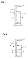
- FIG.1 is a sectional view showing a frame for use in a photovoltaic module according to a first embodiment of the invention
- FIG.2 is a sectional view showing a corner piece mounted in the frame for use in the photovoltaic module according to the first embodiment of the invention
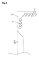
- FIG.3 is a plan view showing the frame and corner piece for use in the photovoltaic module according to the first embodiment of the invention
- FIG.4 is a plan view showing how the frames for use in the photovoltaic module according to the first embodiment of the invention are fixed;
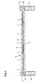
- FIG.5 is a schematic sectional view showing the photovoltaic module according to the first embodiment of the invention.
- FIG.6 is a schematic sectional view showing the essential part of the photovoltaic module according to the first embodiment of the invention.
- FIG.7 is a perspective view showing the frames fixed to each other according to the first embodiment of the invention.
- FIG.8 is a plan view showing how frames for use in a photovoltaic module according to a second embodiment of the invention are fixed;
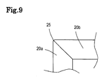
- FIG.9 is a plan view showing the frames for use in the photovoltaic module according to the second embodiment of the invention.
- FIG.10 is a plan view showing a conventional photovoltaic module
- FIG.11 is a schematic sectional view showing the conventional photovoltaic module.
- FIG.12 is a perspective view showing the conventional photovoltaic module.
- FIG.5 is a schematic sectional view showing a photovoltaic module according to a first embodiment of the invention. Referring to this figure, description is made on a general structure of this photovoltaic module.
- the photovoltaic module of the invention includes a plurality of solar cells 11.
- the solar cell 11 comprises, for example, a crystalline semiconductor composed of monocrystalline silicon or polycrystalline silicon having a thickness on the order of 0.15mm and is generally shaped like a square 100 mm on a side.
- the invention is not limited to this and may employ other solar cells.
- an n-type region and a p-type region are formed, for example, while an interfacial area between the n-type region and the p-type region defines a junction for forming an electric field for carrier separation.
- An employed solar cell for example, includes an intrinsic amorphous silicon layer interposed between a monocrystalline silicon substrate and an amorphous silicon substrate for reducing defects in interfaces therebetween. Thus, the solar cell is improved in heterojunction interface characteristic.
- a respective one of the plural solar cells 11 is electrically connected to its adjoining solar cell(s) 11 by means of a wiring material (not shown) made of flat copper foil or the like. Specifically, one end of the wiring material is connected to a collector electrode on an upper side of a certain solar cell 11, while the other end thereof is connected to a collector electrode on a lower side of another solar cell 11 adjoining the certain solar cell 11. An arrangement is made wherein these solar cells 11 are connected in series by means of the wiring material so as to provide a predetermined output of 200W, for example, from a photovoltaic module body 10.
- the photovoltaic module body 10 is constructed such that the plural solar cells 11 are electrically interconnected by means of the wiring material made of a conductive material such as copper foil (not shown) and are sealed between a surface member 12 having translucency, such as glass or translucent plastic, and a backside member 13 comprising a translucent member such as weather-resistant film, glass or translucent plastic with a translucent sealing material 14 such as EVA (Ethylene Vinyl Acetate) having excellent weather resistance and moisture resistance.
- a translucent material such as copper foil (not shown) and are sealed between a surface member 12 having translucency, such as glass or translucent plastic
- a backside member 13 comprising a translucent member such as weather-resistant film, glass or translucent plastic with a translucent sealing material 14 such as EVA (Ethylene Vinyl Acetate) having excellent weather resistance and moisture resistance.
- EVA Ethylene Vinyl Acetate
- the above-described photovoltaic module body 10 is fitted in frames 20 made of aluminum or the like by applying a seal material 40 made of a silicone resin or the like to a periphery thereof.
- the frame 20 is formed of aluminum, stainless steel, roll forming steel sheet or the like.
- a terminal box (not shown) is attached to a surface of the backside member 13, for example.
- an exemplary frame 20 includes a main body 21 having a hollow structure, and a fit-engagement portion 22 located above the main body 21 and having a U-shape in section for fittingly receiving an outer periphery of the photovoltaic module body by intermediary of the seal material.
- the fit-engagement portion 22 is formed with a recess 26 for holding the seal material.
- four frames 20 are provided in correspondence to the four sides of the rectangular photovoltaic module body 10, respectively.
- the frames 20, 20 are coupled and fixed to each other on a corner defined by a respective pair of intersecting sides of the photovoltaic module body.
- the frames 20 are coupled so as to be normal to each other on the corner. Accordingly, the frames 20, 20 have their ends cut at 45 degrees.
- a corner portion of the frame 20 is formed with a rectangular mounting portion 27 into which a corner piece to be described hereinlater is press-inserted.
- the mounting portion 27 has a great outside wall thickness and a small inside wall thickness.
- the mounting portion 27 is constructed such that an outside wall thickness (a) in section is in the range of 1.8mm to 1.5mm and an inside wall thickness (b) in section is in the range of 1.1mm to 1.3mm.
- the mounting portion is constructed such that the total of the outside wall thickness and the inside wall thickness in section is 2.9mm.
- the frame 20 is formed of an aluminum material and the rectangular mounting portion 27 has a width (c) of about 8.8mm and a height (d) of about 20mm.
- the mounting portion 27 is constructed such that if the outside wall thickness (a) in section is 1.6mm, the inside wall thickness (b) in section is 1.3mm.
- the mounting portion 27 is constructed such that the outside wall thickness and the inside wall thickness in section are the same. Either wall thickness is 1.45mm so that the total of these wall thicknesses is 2.9mm.
- this embodiment has the same total wall thickness as that of the conventional frame so that there is no difference in strength, weight or cost between the conventional frame and the frame of the embodiment.
- a corner piece 30 press-inserted in the mounting portion 27 is formed of aluminum and is formed with a hook-like portion 31.
- the hook-like portion 31 of this embodiment has a width (w) of 8.95mm, which is slightly greater than the width (c) of the rectangular mounting portion 27.
- the hook-like portion of this embodiment has a height (h) of 19mm, which is equal to or slightly smaller than the height (b) of the mounting portion 27.
- the frames 20 (20a, 20b) are interconnected as follows. As shown in FIG.2 and FIG.4 , a hook-like portion 31 of the corner piece 30 is press-inserted in the mounting portion 27 of one frame 20 (20a) thereby fixing the corner piece 30 therein. Subsequently, the other hook-like portion 31 of the corner piece 30 is press-inserted in the mounting portion 27 of the other frame 20 (20b) whereby the frames 20a, 20b are fixed to each other.
- the mounting portion 27 has the greater outside wall thickness and the smaller inside wall thickness. Therefore, the mounting portion 27 is significantly deflected at the inside wall but the outside wall thereof undergoes little deflection. As shown in FIG.7 , therefore, there occurs no gap between outer sides of joint surfaces of the frames 20, 20, which gap may result from the deformation or the like of the frames. Thus is eliminated the need for an adjustment work.
- the inside wall of the mounting portion 27 is deflected and deformed inward by an amount represented by 'e' in the figure.
- the deformation amount 'e' was 0.15mm.
- the inward deflection of the inside wall causes a lower side of the fit-engagement portion 22 having the U-shaped section to be deformedly deflected upward by an amount represented by 'f' in the figure.
- the deformation amount 'f' was 0.05mm.
- the portion of the frame 20 that is in contact with the photovoltaic module body 10 is also raised so that fixing relation between the photovoltaic module body 10 and the frame 20 is also enhanced.
- FIG.8 and FIG.9 are plan views showing a second embodiment of the invention.
- the second embodiment is arranged such that joint surfaces on which frames 20c, 20c abut on each other define a chamfered corner.
- the frames 20c, 20c in abutting contact include arc-shaped ends 25.
- the frame 20c has a great outside wall thickness and a small inside wall thickness in section.
- the press-insertion of the corner piece 30 does not cause the deformation of an outside portion of the frame. Therefore, the corner formed by the frames 20c, 20c in abutting contact has a chamfered configuration because the frames 20c in abutting contact have their ends shaped like an arc.
- the chamfered corner is formed so that a person touching the corner with his/her hand or the like may not have pain or painful sensation such as caused upon contact against a sharply-angled article. Hence, the module may be handled more easily.
Landscapes
- Engineering & Computer Science (AREA)
- Physics & Mathematics (AREA)
- Life Sciences & Earth Sciences (AREA)
- Sustainable Development (AREA)
- Sustainable Energy (AREA)
- Thermal Sciences (AREA)
- Chemical & Material Sciences (AREA)
- Combustion & Propulsion (AREA)
- Mechanical Engineering (AREA)
- General Engineering & Computer Science (AREA)
- Photovoltaic Devices (AREA)
Applications Claiming Priority (1)
| Application Number | Priority Date | Filing Date | Title |
|---|---|---|---|
| JP2009039536A JP5361438B2 (ja) | 2009-02-23 | 2009-02-23 | 太陽電池モジュール |
Publications (2)
| Publication Number | Publication Date |
|---|---|
| EP2221879A2 true EP2221879A2 (de) | 2010-08-25 |
| EP2221879A3 EP2221879A3 (de) | 2015-10-07 |
Family
ID=42245595
Family Applications (1)
| Application Number | Title | Priority Date | Filing Date |
|---|---|---|---|
| EP10001778.9A Withdrawn EP2221879A3 (de) | 2009-02-23 | 2010-02-22 | Photovoltaikmodul |
Country Status (5)
| Country | Link |
|---|---|
| US (1) | US8330037B2 (de) |
| EP (1) | EP2221879A3 (de) |
| JP (1) | JP5361438B2 (de) |
| KR (1) | KR101635221B1 (de) |
| CN (1) | CN101820013B (de) |
Cited By (3)
| Publication number | Priority date | Publication date | Assignee | Title |
|---|---|---|---|---|
| EP2657986A1 (de) * | 2012-04-27 | 2013-10-30 | Guzzini Engineering S.R.L. | Photovoltaikmodul und zugehörige Verankerungsstruktur |
| EP2595199A3 (de) * | 2011-11-18 | 2014-06-04 | Hulk Energy Technology Co., Ltd. | Solarzellenmodul |
| CN108964597A (zh) * | 2018-08-08 | 2018-12-07 | 浙江晶科能源有限公司 | 一种双玻光伏组件及光伏发电组 |
Families Citing this family (28)
| Publication number | Priority date | Publication date | Assignee | Title |
|---|---|---|---|---|
| US20100108118A1 (en) * | 2008-06-02 | 2010-05-06 | Daniel Luch | Photovoltaic power farm structure and installation |
| US8884155B2 (en) | 2006-04-13 | 2014-11-11 | Daniel Luch | Collector grid and interconnect structures for photovoltaic arrays and modules |
| US9865758B2 (en) | 2006-04-13 | 2018-01-09 | Daniel Luch | Collector grid and interconnect structures for photovoltaic arrays and modules |
| US20140102997A1 (en) * | 2012-01-17 | 2014-04-17 | Zep Solar, Inc. | Photovoltaic Module Frame |
| US20120298188A1 (en) | 2009-10-06 | 2012-11-29 | Zep Solar, Inc. | Method and Apparatus for Forming and Mounting a Photovoltaic Array |
| US20140339179A1 (en) * | 2009-10-06 | 2014-11-20 | Zep Solar Llc | Photovoltaic module frame |
| KR100984739B1 (ko) * | 2010-04-23 | 2010-10-07 | 대주시스템(주) | 태양광 모듈 프레임 |
| JP5938584B2 (ja) | 2010-09-28 | 2016-06-22 | パナソニックIpマネジメント株式会社 | 太陽電池モジュール |
| US20120073630A1 (en) * | 2010-09-28 | 2012-03-29 | Perfect Source Technology Corp. | Rectangular protective frame for solar cell module |
| KR101731460B1 (ko) * | 2011-01-10 | 2017-05-04 | 주성엔지니어링(주) | 태양전지 패널을 조립하는 프레임 |
| KR101050172B1 (ko) * | 2011-03-30 | 2011-07-19 | 한명전기주식회사 | 압착결합방식의 프레임이 형성된 태양전지판 및 그 조립방법 |
| KR101067951B1 (ko) * | 2011-04-19 | 2011-09-26 | 조영현 | 태양전지 모듈 프레임 |
| TWM426878U (en) * | 2011-11-25 | 2012-04-11 | Hulk Energy Technology Co Ltd | Frame structure of solar energy module |
| JP5916565B2 (ja) * | 2012-08-28 | 2016-05-11 | シャープ株式会社 | 太陽電池モジュール |
| KR101393219B1 (ko) * | 2012-04-17 | 2014-05-09 | 엘지전자 주식회사 | 태양전지 패널 및 이의 설치 구조 |
| CN102820351B (zh) * | 2012-08-16 | 2014-11-26 | 常州天合光能有限公司 | 一种太阳能组件安装结构 |
| TWI539614B (zh) * | 2012-09-14 | 2016-06-21 | 豪客能源科技股份有限公司 | 太陽能電池模組 |
| KR102196928B1 (ko) * | 2013-11-26 | 2020-12-30 | 엘지전자 주식회사 | 태양 전지 모듈 및 이에 사용되는 프레임 |
| CN104752538A (zh) | 2013-12-27 | 2015-07-01 | 比亚迪股份有限公司 | 双玻光伏电池组件 |
| JP2017099033A (ja) * | 2014-03-28 | 2017-06-01 | パナソニックIpマネジメント株式会社 | 連結部材、太陽電池モジュール及び太陽電池モジュールの製造方法 |
| JP6325898B2 (ja) * | 2014-05-28 | 2018-05-16 | シャープ株式会社 | 太陽電池モジュールおよび太陽電池モジュール用枠体 |
| JP6678341B2 (ja) * | 2015-12-01 | 2020-04-08 | パナソニックIpマネジメント株式会社 | 太陽電池モジュール |
| JP6869014B2 (ja) * | 2016-11-25 | 2021-05-12 | シャープ株式会社 | 太陽電池モジュール及びその製造方法 |
| CN107316910B (zh) * | 2017-06-02 | 2019-06-11 | 江西仁江科技有限公司 | 一种无胶封装光伏组件 |
| CN111384893A (zh) * | 2018-12-27 | 2020-07-07 | 汉能移动能源控股集团有限公司 | 光伏组件安装结构及光伏组件 |
| KR200497838Y1 (ko) * | 2021-08-31 | 2024-03-13 | 주식회사 강산에 | 옥외형 개별조명등용 태양광패널 탑재프레임 |
| JP7705321B2 (ja) * | 2021-09-13 | 2025-07-09 | ソーラーフロンティア株式会社 | 光電変換モジュールの解体方法、切断補助具及び切断システム |
| JP7609743B2 (ja) * | 2021-09-13 | 2025-01-07 | ソーラーフロンティア株式会社 | 光電変換モジュールの解体方法 |
Citations (2)
| Publication number | Priority date | Publication date | Assignee | Title |
|---|---|---|---|---|
| JP2007095819A (ja) | 2005-09-27 | 2007-04-12 | Sanyo Electric Co Ltd | 太陽電池モジュール |
| JP2009039536A (ja) | 1996-12-09 | 2009-02-26 | Baxter Internatl Inc | 栄養流体調合アセンブリ |
Family Cites Families (8)
| Publication number | Priority date | Publication date | Assignee | Title |
|---|---|---|---|---|
| US4452138A (en) * | 1982-06-17 | 1984-06-05 | American Screen Printing Equipment Co. | Screen printing frame |
| DE3611542A1 (de) * | 1986-04-05 | 1987-10-08 | Remscheid Volksbank | Solarmodul |
| JP2000308554A (ja) * | 1999-02-26 | 2000-11-07 | Nisshinbo Ind Inc | 枠 体 |
| JP3907668B2 (ja) * | 2005-04-07 | 2007-04-18 | シャープ株式会社 | 太陽電池モジュールの取付け構造 |
| US7735484B2 (en) * | 2007-06-06 | 2010-06-15 | Atomic Energy Council | Light-collecting base-body structure |
| JP2010532088A (ja) * | 2007-06-19 | 2010-09-30 | ビーピー・コーポレーション・ノース・アメリカ・インコーポレーテッド | ソーラーパネル取付用枠を有するソーラーモジュール |
| DE202007016429U1 (de) * | 2007-11-22 | 2008-03-20 | Vincenz, Manuela | Rahmensystem für Solarkollektoren |
| TWM362383U (en) * | 2009-03-26 | 2009-08-01 | Sintek Photronic Corp | Assembly frame for use in solar substrate |
-
2009
- 2009-02-23 JP JP2009039536A patent/JP5361438B2/ja not_active Expired - Fee Related
-
2010
- 2010-02-22 KR KR1020100015565A patent/KR101635221B1/ko not_active Expired - Fee Related
- 2010-02-22 EP EP10001778.9A patent/EP2221879A3/de not_active Withdrawn
- 2010-02-22 US US12/709,958 patent/US8330037B2/en not_active Expired - Fee Related
- 2010-02-23 CN CN201010176760.XA patent/CN101820013B/zh active Active
Patent Citations (2)
| Publication number | Priority date | Publication date | Assignee | Title |
|---|---|---|---|---|
| JP2009039536A (ja) | 1996-12-09 | 2009-02-26 | Baxter Internatl Inc | 栄養流体調合アセンブリ |
| JP2007095819A (ja) | 2005-09-27 | 2007-04-12 | Sanyo Electric Co Ltd | 太陽電池モジュール |
Cited By (4)
| Publication number | Priority date | Publication date | Assignee | Title |
|---|---|---|---|---|
| EP2595199A3 (de) * | 2011-11-18 | 2014-06-04 | Hulk Energy Technology Co., Ltd. | Solarzellenmodul |
| EP2657986A1 (de) * | 2012-04-27 | 2013-10-30 | Guzzini Engineering S.R.L. | Photovoltaikmodul und zugehörige Verankerungsstruktur |
| CN108964597A (zh) * | 2018-08-08 | 2018-12-07 | 浙江晶科能源有限公司 | 一种双玻光伏组件及光伏发电组 |
| CN108964597B (zh) * | 2018-08-08 | 2024-03-29 | 浙江晶科能源有限公司 | 一种双玻光伏组件及光伏发电组 |
Also Published As
| Publication number | Publication date |
|---|---|
| KR20100096019A (ko) | 2010-09-01 |
| CN101820013B (zh) | 2014-03-12 |
| CN101820013A (zh) | 2010-09-01 |
| EP2221879A3 (de) | 2015-10-07 |
| JP2010199147A (ja) | 2010-09-09 |
| US20100212723A1 (en) | 2010-08-26 |
| JP5361438B2 (ja) | 2013-12-04 |
| KR101635221B1 (ko) | 2016-06-30 |
| US8330037B2 (en) | 2012-12-11 |
Similar Documents
| Publication | Publication Date | Title |
|---|---|---|
| US8330037B2 (en) | Photovoltaic module | |
| US8927850B2 (en) | Photovoltaic module | |
| US8063301B2 (en) | Photovoltaic module | |
| JP4368151B2 (ja) | 太陽電池モジュール | |
| US20090050190A1 (en) | Solar cell and solar cell module | |
| EP1763088B1 (de) | Photovoltaisches Modul | |
| JP5938584B2 (ja) | 太陽電池モジュール | |
| JP5879537B2 (ja) | 太陽電池パネル、太陽電池モジュールおよび太陽電池モジュールの製造方法 | |
| JP5556146B2 (ja) | 太陽電池モジュールの製造方法 | |
| JPWO2013061995A1 (ja) | 太陽電池モジュールおよび太陽電池アレイ | |
| US20100243026A1 (en) | Solar cell module and solar cell | |
| JP2006073707A (ja) | 太陽電池モジュール | |
| CN120343989B (zh) | 一种背接触光伏组件 | |
| JP5147754B2 (ja) | 太陽電池モジュール | |
| JP2011155217A (ja) | 太陽電池モジュール | |
| JP2001077394A (ja) | 雪止め金具を使用した太陽電池モジュールアレイおよびその固定方法 | |
| US20120024339A1 (en) | Photovoltaic Module Including Transparent Sheet With Channel | |
| JP2006165169A (ja) | 太陽電池モジュール、その製造方法及び、その施工方法 | |
| CN222052971U (zh) | 一种光伏组件 | |
| CN205985025U (zh) | 一种双面发电光伏组件 | |
| CN119789546B (zh) | 光伏组件 | |
| CN222692239U (zh) | 一种光伏组件 | |
| WO2011093377A1 (ja) | 太陽電池モジュール | |
| WO2012017994A1 (ja) | 太陽電池モジュール | |
| CN121568439A (zh) | 光伏组件 |
Legal Events
| Date | Code | Title | Description |
|---|---|---|---|
| PUAI | Public reference made under article 153(3) epc to a published international application that has entered the european phase |
Free format text: ORIGINAL CODE: 0009012 |
|
| AK | Designated contracting states |
Kind code of ref document: A2 Designated state(s): AT BE BG CH CY CZ DE DK EE ES FI FR GB GR HR HU IE IS IT LI LT LU LV MC MK MT NL NO PL PT RO SE SI SK SM TR |
|
| AX | Request for extension of the european patent |
Extension state: AL BA RS |
|
| PUAL | Search report despatched |
Free format text: ORIGINAL CODE: 0009013 |
|
| AK | Designated contracting states |
Kind code of ref document: A3 Designated state(s): AT BE BG CH CY CZ DE DK EE ES FI FR GB GR HR HU IE IS IT LI LT LU LV MC MK MT NL NO PL PT RO SE SI SK SM TR |
|
| AX | Request for extension of the european patent |
Extension state: AL BA RS |
|
| RIC1 | Information provided on ipc code assigned before grant |
Ipc: F24J 2/52 20060101ALI20150902BHEP Ipc: H01L 31/042 20140101AFI20150902BHEP |
|
| RAP1 | Party data changed (applicant data changed or rights of an application transferred) |
Owner name: PANASONIC INTELLECTUAL PROPERTY MANAGEMENT CO., LT |
|
| 17P | Request for examination filed |
Effective date: 20160405 |
|
| RBV | Designated contracting states (corrected) |
Designated state(s): AT BE BG CH CY CZ DE DK EE ES FI FR GB GR HR HU IE IS IT LI LT LU LV MC MK MT NL NO PL PT RO SE SI SK SM TR |
|
| RIC1 | Information provided on ipc code assigned before grant |
Ipc: F24S 25/20 20180101AFI20180416BHEP |
|
| GRAP | Despatch of communication of intention to grant a patent |
Free format text: ORIGINAL CODE: EPIDOSNIGR1 |
|
| STAA | Information on the status of an ep patent application or granted ep patent |
Free format text: STATUS: GRANT OF PATENT IS INTENDED |
|
| RIC1 | Information provided on ipc code assigned before grant |
Ipc: H02S 30/10 20140101AFI20180709BHEP Ipc: F24S 25/20 20180101ALI20180709BHEP Ipc: H02S 20/00 20140101ALI20180709BHEP |
|
| INTG | Intention to grant announced |
Effective date: 20180803 |
|
| STAA | Information on the status of an ep patent application or granted ep patent |
Free format text: STATUS: THE APPLICATION IS DEEMED TO BE WITHDRAWN |
|
| 18D | Application deemed to be withdrawn |
Effective date: 20181214 |