EP2221936A2 - System und Verfahren zur Steuerung eines am Netz angeschlossenen Stromerzeugungssystems - Google Patents
System und Verfahren zur Steuerung eines am Netz angeschlossenen Stromerzeugungssystems Download PDFInfo
- Publication number
- EP2221936A2 EP2221936A2 EP10150922A EP10150922A EP2221936A2 EP 2221936 A2 EP2221936 A2 EP 2221936A2 EP 10150922 A EP10150922 A EP 10150922A EP 10150922 A EP10150922 A EP 10150922A EP 2221936 A2 EP2221936 A2 EP 2221936A2
- Authority
- EP
- European Patent Office
- Prior art keywords
- converter
- power
- controller
- voltage
- current
- Prior art date
- Legal status (The legal status is an assumption and is not a legal conclusion. Google has not performed a legal analysis and makes no representation as to the accuracy of the status listed.)
- Granted
Links
Images


Classifications
-
- H—ELECTRICITY
- H02—GENERATION; CONVERSION OR DISTRIBUTION OF ELECTRIC POWER
- H02J—ELECTRIC POWER NETWORKS; CIRCUIT ARRANGEMENTS OR SYSTEMS FOR SUPPLYING OR DISTRIBUTING ELECTRIC POWER; SYSTEMS FOR STORING ELECTRIC ENERGY
- H02J3/00—Circuit arrangements for AC mains or AC distribution networks
- H02J3/38—Arrangements for feeding a single network from two or more generators or sources in parallel; Arrangements for feeding already energised networks from additional generators or sources in parallel
- H02J3/381—Dispersed generators
-
- H—ELECTRICITY
- H02—GENERATION; CONVERSION OR DISTRIBUTION OF ELECTRIC POWER
- H02J—ELECTRIC POWER NETWORKS; CIRCUIT ARRANGEMENTS OR SYSTEMS FOR SUPPLYING OR DISTRIBUTING ELECTRIC POWER; SYSTEMS FOR STORING ELECTRIC ENERGY
- H02J3/00—Circuit arrangements for AC mains or AC distribution networks
- H02J3/38—Arrangements for feeding a single network from two or more generators or sources in parallel; Arrangements for feeding already energised networks from additional generators or sources in parallel
- H02J3/46—Controlling the sharing of generated power between the generators, sources or networks
-
- H—ELECTRICITY
- H02—GENERATION; CONVERSION OR DISTRIBUTION OF ELECTRIC POWER
- H02J—ELECTRIC POWER NETWORKS; CIRCUIT ARRANGEMENTS OR SYSTEMS FOR SUPPLYING OR DISTRIBUTING ELECTRIC POWER; SYSTEMS FOR STORING ELECTRIC ENERGY
- H02J2101/00—Supply or distribution of decentralised, dispersed or local electric power generation
- H02J2101/20—Dispersed power generation using renewable energy sources
- H02J2101/28—Wind energy
-
- Y—GENERAL TAGGING OF NEW TECHNOLOGICAL DEVELOPMENTS; GENERAL TAGGING OF CROSS-SECTIONAL TECHNOLOGIES SPANNING OVER SEVERAL SECTIONS OF THE IPC; TECHNICAL SUBJECTS COVERED BY FORMER USPC CROSS-REFERENCE ART COLLECTIONS [XRACs] AND DIGESTS
- Y02—TECHNOLOGIES OR APPLICATIONS FOR MITIGATION OR ADAPTATION AGAINST CLIMATE CHANGE
- Y02E—REDUCTION OF GREENHOUSE GAS [GHG] EMISSIONS, RELATED TO ENERGY GENERATION, TRANSMISSION OR DISTRIBUTION
- Y02E10/00—Energy generation through renewable energy sources
- Y02E10/70—Wind energy
- Y02E10/72—Wind turbines with rotation axis in wind direction
-
- Y—GENERAL TAGGING OF NEW TECHNOLOGICAL DEVELOPMENTS; GENERAL TAGGING OF CROSS-SECTIONAL TECHNOLOGIES SPANNING OVER SEVERAL SECTIONS OF THE IPC; TECHNICAL SUBJECTS COVERED BY FORMER USPC CROSS-REFERENCE ART COLLECTIONS [XRACs] AND DIGESTS
- Y02—TECHNOLOGIES OR APPLICATIONS FOR MITIGATION OR ADAPTATION AGAINST CLIMATE CHANGE
- Y02E—REDUCTION OF GREENHOUSE GAS [GHG] EMISSIONS, RELATED TO ENERGY GENERATION, TRANSMISSION OR DISTRIBUTION
- Y02E10/00—Energy generation through renewable energy sources
- Y02E10/70—Wind energy
- Y02E10/76—Power conversion electric or electronic aspects
Definitions
- the present invention relates generally to power generating systems connected to a grid and, more particularly, to control of power generating systems during weak grid operation.
- Wind turbine generators are regarded as environmentally friendly and relatively inexpensive alternative sources of energy that utilize wind energy to produce electrical power.
- Wind turbines can be distinguished in two types: fixed speed and variable speed turbines.
- the variable speed wind turbines are controlled as current sources connected to a power grid.
- the variable speed wind turbines rely on a grid frequency detected by a phase locked loop (PLL) as a reference and inject a specified amount of current into the grid.
- PLL phase locked loop
- the conventional current source control of the wind turbines is based on the assumptions that the grid voltage waveforms are fundamental voltage waveforms with fixed frequency and magnitude and that the penetration of wind power into the grid is low enough so as to not result in disturbances. Thus, the wind turbines simply inject the specified current into the grid based on the fundamental voltage waveforms. However, with the rapid growth of the wind power, wind power penetration into some grids has increased to the point where wind turbine generators have a significant impact on the grid voltage and frequency.
- a power generating system in accordance with one exemplary embodiment of the present invention, includes a wind turbine and a converter to couple the wind turbine to a power grid.
- the system further includes a first controller for calculating voltage commands to emulate a phasor back electromotive force behind an inductance.
- the controller further generates converter switching commands based on the voltage commands.
- the voltage commands include a voltage magnitude reference, an internal frequency reference calculated from a power imbalance between an active power reference and the electrical power.
- the system also includes a second controller to limit a converter current.
- a solar power generating system in accordance with another exemplary embodiment, includes a photovoltaic cell and a converter to couple the photovoltaic cell to a power grid.
- the system further includes a first controller for calculating voltage commands to emulate a phasor back electromotive force behind an inductance.
- the controller further generates converter switching commands based on the voltage commands.
- the voltage commands include a voltage magnitude reference, an internal frequency reference calculated from a power imbalance between a mechanical power reference and the electrical power.
- the system also includes a second controller to limit a converter current magnitude.
- a method for supplying electrical power to a power grid includes generating the electrical power from an electrical source and controlling the electrical source to emulate a phasor back electromotive force behind an inductance.
- the method further includes limiting a converter current magnitude.
- controlling the electrical source includes calculating voltage commands and using the voltage commands for generating converter switching commands, wherein the voltage commands include a voltage magnitude reference, an internal frequency reference calculated from an imbalance between a mechanical power reference and the electrical power.
- various embodiments of the present invention function to provide methods and systems to control grid connected power generating systems.
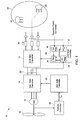
- FIG. 1 shows a conventional grid connected wind power generating system 10 with current source control.
- the system includes a wind generator 12, a generator side converter 14 and a grid side converter 16.
- the system further includes a grid side controller 18, a generator side controller 20 and a power grid 22.
- the power grid 22 typically includes traditional synchronous generators 24 and electrical loads 26.
- a direct current (DC) link 28 connects the generator side converter 14 and the grid side converter 16.
- the generator side converter 14 converts alternating current (AC) power generated by the wind generator 12 into DC power.
- the grid side converter 18 then converts the DC power to AC power at a frequency compatible with the power grid 22.
- the combination of the grid side controller 18 and grid side converter 16 functions as a current source for the grid 22.
- the grid side controller 18 controls the phase and amplitude of the output current 30 of grid side converter 16.
- the grid side controller includes a phase locked loop (PLL) 32, a DC voltage regulator 34, a current regulator 36 and a reactive power regulator 40.
- the PLL 32 senses three phase voltages of the power grid and generates a frequency and phase reference for the grid side converter 16.
- the DC voltage regulator 34 helps in maintaining the DC link voltage at a desired value, and the reactive power regulator 40 helps in supplying desired amount of reactive power into the grid.
- the current regulator 36 generates the output current reference for the grid side converter 16 based on the PLL output, the DC voltage regulator output, and the reactive power regulator output.
- the generator side controller 20 generates switching signals for the generator side converter 14.
- a turbine controller 38 provides a torque reference to the generator side controller 20 based on wind velocity or rotor speed of the wind turbine. The turbine controller generates the torque reference such that maximum energy is captured from the wind.
- the current source control of the wind power generating system 10 of FIG. 1 maintains the output current of the wind turbine 42 based on the frequency and phase of the grid voltage detected by PLL.
- the output current will have significant impact on the grid voltage.
- the PLL is generating the output current reference based on the grid voltage and as the grid voltage is dependent on the output current itself, stability problems may occur. Stability issues may also occur because of the limited bandwidth of current source control.
- the current source control responds slowly to high frequency voltage distortions. Thus, in a current source control wind power generating system the output currents cannot always follow the grid voltage distortions due to grid network resonance conditions.
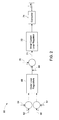
- FIG. 2 shows a grid side converter control block diagram 60 of the wind power generating system of FIG. 1 .
- a reference DC link voltage command 62, an actual DC voltage feedback 64, a reference reactive power command 66, and an actual reactive power feedback 67 are inputs to an output closed loop regulator 68.
- the outer closed loop control regulator 68 generates the reference current commands 69.
- a current feedback 70 is subtracted from the reference current commands 69 and then the error signals 71 are provided to an inner current loop regulator 72.
- the inner current loop regulator 72 provides switching signals to the grid side converter 74.
- the frequency and the phase reference for the current source are generated by the PLL 30 ( FIG. 1 ).
- the grid side converter 74 injects the current into the grid.
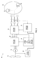
- FIG. 3 shows a grid connected wind power generating system 90 with voltage source control in accordance with one embodiment of the present invention.
- the wind power generating system 90 includes the wind generator 12, the generator side converter 14, and the grid side converter 16.
- the system further includes the grid side controller 18, the generator side controller 20 and the power grid 22.
- the wind generator 12 comprises a squirrel cage induction generator.
- the wind generator 12 may comprise a synchronous generator or a permanent magnet synchronous generator.
- the generator side controller 20 generates the switching signals for the generator side converter 14.
- the generator side controller helps in maintaining the DC link voltage to a desired value.
- the grid side converter 16 is controlled as a voltage source connected to the grid 22.
- the grid side controller 18 controls the phase and amplitude of the output voltage of grid side converter directly.
- the grid side converter when controlled as the voltage source, responds to grid changes as a voltage behind a reactance.
- the wind generator 12 operates in a similar manner as a synchronous generator.
- the grid side controller of the embodiment of FIG. 3 receives the power reference from the turbine controller 38.
- An internal frequency reference is generated based on the power imbalance between the reference power and the actual electrical power supplied to the grid.
- a power/frequency (P/F) regulator (not shown) may be used to share the power with other wind turbines, i.e., for paralleling operation of wind turbines.
- the power frequency regulator determines the phase angle reference for the grid side controller 18.
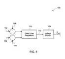
- FIG. 4 shows a grid side converter control block diagram 100 of the wind power generating system of FIG. 3 , in accordance with one embodiment of the present invention.
- a reference active power command 102 and a reference reactive power command 104 are inputs to an outer closed loop controller 110.
- a measured active power feedback 106 and a measured reactive power feedback 108 are also fed back to the outer closed loop regulator 110.
- the outer closed loop control regulator 110 generates the voltage commands 112 for a voltage source 114, and voltage commands 112 include both the magnitude command and frequency/phase command.
- the voltage source 114 may include a second controller (not shown) to limit the converter current and the grid side converter 16 of FIG. 3 .
- the voltage source 114 generates the output voltage and feeds the active power into the grid.
- FIG. 5 shows a detailed control system 130 for the grid side converter, in accordance with an embodiment of the present invention.
- the turbine controller 38 generates an active or mechanical power reference 102 or a mechanical power reference or a torque reference for the control system 130.
- An internal frequency reference 132 is generated based on the difference between or imbalance between the actual electrical power supplied to the grid 134 and the reference mechanical power 102. It should be noted here that the internal frequency reference 132 is different than the grid frequency.
- a reference phase angle 136 for the control system 130 is generated by integrating the frequency reference 132.
- the PLL 32 is not used to generate the frequency reference or the phase reference. The PLL 32 is used only for protection purposes and ensures that the reference phase angle does not differ too much from the actual measured PLL angle.
- a farm controller 138 generates the reactive power reference 104 for the control system 130, and a reactive power regulator 110 generates voltage reference 140 for the control system 130.
- the grid side converter is controlled as a voltage source or controlled to emulate a back-electromotive force (EMF) behind an inductance.
- EMF is controlled by the voltage magnitude reference 140 and the internal frequency reference 132.
- control system 132 also includes an abc-xy transformation matrix 142 for voltage transformation.
- the transformation matrix 142 converts 3-phase stationary quantities into 2-phase rotating quantities.
- the reverse transformation xy - abc matrix 144 converts the 2-phase rotating voltage coordinates into 3-phase stationary voltage coordinates.
- the voltage regulator 146 determines the voltage commands that need to be generated by the grid side converter.
- the benefit of this control system is the grid side converter responds to the load changes in grid very quickly, as the grid side converter is directly following voltage commands.
- FIG. 6 shows a control system 150 with a current limiter of the wind power generating system of FIG. 3 , in accordance with one embodiment of the present invention.
- the voltage source controlled grid side converter 16 of FIG. 3 generates the voltage that follows the reference voltage commands. If there is no inherent current control, during grid transient or fault events the converter current may rise and exceed the current limit of switching devices of the converter.
- a current detector 152 and a current limiter 154 are used in the control system 150 to limit the converter current or to protect the converter.
- the current limiter 154 may be an instantaneous current limiter or a phasor current limiter or a combination of both. The instantaneous current limiter acts immediately and chops the current, whereas the phasor current limiter acts more slowly to limit the root mean square (RMS) current.
- RMS root mean square
- FIG. 7 is a block diagram of an instantaneous current limiter 160, in accordance with an embodiment of the present invention.
- the current limiter 160 receives three phase voltage commands 162, 164, 166 that the grid side converter needs to produce. For each command, a modulator block 168, a disable switching block 170 and a switch block 172 together generate switching signals for the respective switching devices of the grid side converter.
- a current detection signal 174 triggers the switch blocks 172 when the current is higher than a threshold value. In one embodiment, when the switch blocks 172 are triggered, the switching signals to the switching devices of the grid side converter are blocked. In one embodiment, the current detection signal is common for all the switching blocks.
- any single-phase current exceeds the threshold value, it triggers all the switching blocks of all the three phases and blocks switching signals to the switching devices of the grid side converter.
- three separate current detections signals trigger three separate switching blocks, and the three separate current detection signals are generated from three phase currents of the grid side converter.
- the current limiter 160 prevents over current in the grid side converter.
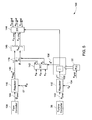
- FIG. 8 shows a phasor diagram 210 representing an implementation of a phasor current limiter in accordance with an embodiment of the present invention.
- the phasor diagram 210 is shown along with a grid side converter circuit 212 of a wind power generating system.
- the phasor diagram 210 shows, a grid side voltage ⁇ .
- An output voltage of the grid side converter ⁇ i is a vector sum of the grid side voltage ⁇ and an impedance voltage drop Z ⁇ i ⁇ i across a known impedance Z ⁇ i associated with the wind turbine converter.
- the phasor diagram 210 also shows a current ⁇ i , injected into the grid by the grid side converter.
- the current ⁇ i lags the voltage grid side voltage ⁇ as shown in phasor diagram 210.
- the grid voltage ⁇ further lags the output voltage of the grid side converter ⁇ i by an angle ⁇ i .
- the phasor current magnitude ⁇ i can be managed by limiting the voltage drop (magnitude and angle) across the impedance Z ⁇ i .
- E f is a measure of E and is a filtered quantity to eliminate the ripple components.
- P f is a measure of the active power.
- the converter internal voltage limits ( E min and E max ) are calculated from the known current limit value I max and an estimated converter reactance X i .
- I max represents maximum output of the current limit regulator 154 of FIG. 6 .
- the phasor current magnitude limit is achieved by keeping ⁇ i within the dashed circle i.e., the circle formed by E min and E max . It should be noted that E max and E min are only rough boundaries to keep ⁇ i within the dashed circle.
- a current limit regulator is used to precisely limit the current.
- the angle limit is achieved by adjusting a power limit P max . At rated voltage, the active power P f is limited to P max by keeping ⁇ i below the dotted P max line.
- the power limit P max is a fixed value.
- the power limit P max is a function of I max .
- the phase angle is decreased.
- an active regulator loop is closed on I max to precisely control for the desired current limit value.
- controlling the difference in voltages will not distinguish between correct X i I max and incorrect X i paired with a compensating incorrect I max .
- the voltage source control of present invention is applied in a doubly fed asynchronous generator system.
- the grid-side converter maintains the DC link voltage, and the generator-side converter is controlled as a voltage source behind an inductance.
- the generator-side active rectifier converts variable-frequency AC power into DC power, and the grid-side converter is controlled as a voltage source behind an inductance.
- the voltage source control of the present invention is also useful in islanding operation.
- the application of power sources to island-able power grids can suffer poor dynamics resulting from current control temporarily defeating the voltage output. This can be a detriment when a load suddenly requires a change in current to remain at the same voltage. Loads can be susceptible to even temporary voltage changes. While the system control would prefer voltage magnitude and frequency in favor of active and reactive power, so long as sufficient power is available, removing the imbedded current regulation from the normal transient load response can provide this.
- control method can also be used in other uncontrollable power generating systems connected to the power grid such as photovoltaic systems or fuel cell systems.
- the grid side converter may also be operated as voltage source controlled converter.
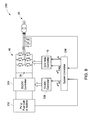
- FIG. 9 shows an embodiment of a power generating system 230, wherein the control system of present invention is implemented.
- the power generating system includes an electrical source 232 connected to the power grid 22.
- the electrical source may be a photovoltaic cell or a fuel cell or a battery.
- the electrical source is connected to the grid through a DC/DC converter 234, the DC link 28 and a grid side converter 16.
- the DC/DC converter 234 maintains a constant DC voltage at the DC link 28 by controlling the energy flow from the energy source 232 to the power grid 234.
- the DC/DC converter 234 is controlled by a controller 236.
- the grid side converter 16 is controlled as a voltage source connected to the grid 22.
- the grid side controller 18 controls the phase and amplitude of the output voltage of grid side converter directly.
- the system controller 238 generates a reference DC voltage command, a reference output voltage magnitude command, and a reference frequency command for the DC/DC converter 234 and grid side converter 16.
Landscapes
- Engineering & Computer Science (AREA)
- Power Engineering (AREA)
- Control Of Eletrric Generators (AREA)
- Supply And Distribution Of Alternating Current (AREA)
Applications Claiming Priority (1)
| Application Number | Priority Date | Filing Date | Title |
|---|---|---|---|
| US12/358,327 US7804184B2 (en) | 2009-01-23 | 2009-01-23 | System and method for control of a grid connected power generating system |
Publications (3)
| Publication Number | Publication Date |
|---|---|
| EP2221936A2 true EP2221936A2 (de) | 2010-08-25 |
| EP2221936A3 EP2221936A3 (de) | 2015-07-29 |
| EP2221936B1 EP2221936B1 (de) | 2016-12-07 |
Family
ID=42230869
Family Applications (1)
| Application Number | Title | Priority Date | Filing Date |
|---|---|---|---|
| EP10150922.2A Revoked EP2221936B1 (de) | 2009-01-23 | 2010-01-18 | System und Verfahren zur Steuerung eines am Netz angeschlossenen Stromerzeugungssystems |
Country Status (4)
| Country | Link |
|---|---|
| US (1) | US7804184B2 (de) |
| EP (1) | EP2221936B1 (de) |
| CN (1) | CN101860038B (de) |
| DK (1) | DK2221936T3 (de) |
Cited By (5)
| Publication number | Priority date | Publication date | Assignee | Title |
|---|---|---|---|---|
| KR20130014394A (ko) * | 2011-07-29 | 2013-02-07 | 제너럴 일렉트릭 캄파니 | 천이 이벤트 전압 보상 능력을 갖는 전력 변환 시스템 및 그 방법 |
| US20130134710A1 (en) * | 2011-05-30 | 2013-05-30 | Xiaoming Yuan | System and method for converter switching frequency control |
| US11394317B2 (en) | 2018-03-16 | 2022-07-19 | Siemens Gamesa Renewable Energy A/S | Converter network bridge controller |
| DE102021206502A1 (de) | 2021-06-23 | 2022-12-29 | Fraunhofer-Gesellschaft zur Förderung der angewandten Forschung eingetragener Verein | Regelvorrichtung für einen Stromrichter, Stromrichteranordnung und Verfahren zum Regeln eines netzgekoppelten Stromrichters |
| EP4082108B1 (de) | 2019-12-23 | 2024-02-14 | Vestas Wind Systems A/S | Windturbine mit virtuellem synchrongenerator mit dämpfungsregelung |
Families Citing this family (118)
| Publication number | Priority date | Publication date | Assignee | Title |
|---|---|---|---|---|
| JP3918837B2 (ja) * | 2004-08-06 | 2007-05-23 | 株式会社日立製作所 | 風力発電装置 |
| EP1914419B1 (de) * | 2006-10-19 | 2015-09-16 | Siemens Aktiengesellschaft | Windenergieanlage und Verfahren zur Steuerung der Ausgangsleistung einer Windenergieanlage |
| US8237301B2 (en) * | 2008-01-31 | 2012-08-07 | General Electric Company | Power generation stabilization control systems and methods |
| DE102008023048A1 (de) * | 2008-05-09 | 2009-11-12 | Voith Patent Gmbh | Wellenkraftwerk und Verfahren für dessen Betrieb |
| US9496717B2 (en) * | 2008-10-28 | 2016-11-15 | Technical University Of Denmark | System and method for connecting a converter to a utility grid |
| US7804184B2 (en) * | 2009-01-23 | 2010-09-28 | General Electric Company | System and method for control of a grid connected power generating system |
| EP2224129B1 (de) * | 2009-02-27 | 2016-09-21 | Acciona Windpower S.a. | Steuerverfahren einer Windturbine zum Dämpfen von Schwingungen |
| CA2762184A1 (en) | 2009-05-12 | 2010-11-18 | Icr Turbine Engine Corporation | Gas turbine energy storage and conversion system |
| US8655495B2 (en) * | 2009-06-24 | 2014-02-18 | Vestas Wind Systems A/S | Current control of a wind park |
| CN101630850B (zh) * | 2009-08-07 | 2011-07-13 | 深圳市禾望电气有限公司 | 一种双馈型感应发电机穿越电网故障的装置及方法 |
| DE102009037238B3 (de) * | 2009-08-12 | 2010-12-09 | Repower Systems Ag | Windenergieanlage mit veränderbarer Drehzahlkennlinie |
| US9478987B2 (en) * | 2009-11-10 | 2016-10-25 | Siemens Aktiengesellschaft | Power oscillation damping employing a full or partial conversion wind turbine |
| EP2529462B1 (de) * | 2010-01-26 | 2016-12-28 | Vestas Wind Systems A/S | Verfahren zur emulationvon synchronmaschine |
| US8866334B2 (en) | 2010-03-02 | 2014-10-21 | Icr Turbine Engine Corporation | Dispatchable power from a renewable energy facility |
| US8984895B2 (en) | 2010-07-09 | 2015-03-24 | Icr Turbine Engine Corporation | Metallic ceramic spool for a gas turbine engine |
| US8018083B2 (en) * | 2010-08-05 | 2011-09-13 | General Electric Company | HVDC connection of wind turbine |
| EP2603696B1 (de) * | 2010-08-13 | 2015-04-08 | Vestas Wind Systems A/S | Windkrafterzeugung mit verringerten Leistungsschwankungen |
| EP2606548B1 (de) | 2010-08-18 | 2015-09-23 | Vestas Wind Systems A/S | Verfahren zur steuerung eines netzseitigen wandlers einer windturibine und dafür geeignetes system |
| AU2011295668A1 (en) | 2010-09-03 | 2013-05-02 | Icr Turbine Engine Corporation | Gas turbine engine configurations |
| KR101243181B1 (ko) * | 2010-11-04 | 2013-03-14 | 한국전기연구원 | 궤환선형화 방법을 이용한 권선형유도발전기 제어장치 |
| EP2453133B1 (de) * | 2010-11-11 | 2017-10-11 | Ingeteam Power Technology, S.A. | Stromwandlersteuerungsverfahren |
| US8174150B2 (en) * | 2010-12-13 | 2012-05-08 | General Electric Company | System and method for control of a grid connected power generating system |
| CN102570868B (zh) * | 2010-12-22 | 2015-04-01 | 通用电气公司 | 电力转换系统和方法 |
| EP2477298B1 (de) * | 2011-01-15 | 2021-04-21 | GE Energy Power Conversion Technology Limited | Steuerungen für statische Energieversorgungseinheiten |
| US9051873B2 (en) | 2011-05-20 | 2015-06-09 | Icr Turbine Engine Corporation | Ceramic-to-metal turbine shaft attachment |
| CN102904273B (zh) * | 2011-07-29 | 2015-05-20 | 通用电气公司 | 能量转换系统的最大功率点追踪控制和相关方法 |
| CN103023361B (zh) * | 2011-09-23 | 2015-12-16 | 通用电气公司 | 能量转换系统及其操作方法、光伏发电系统 |
| JP5376092B2 (ja) | 2011-09-26 | 2013-12-25 | 日本電気株式会社 | 電力接続制御システム及び方法 |
| EP2761171B1 (de) * | 2011-09-30 | 2016-01-13 | Vestas Wind Systems A/S | Schnelle Rücklaufsteuerung mit Anlagenverlusten |
| US8787052B2 (en) | 2011-12-13 | 2014-07-22 | General Electric Company | Methods and systems for controlling a power conversion device |
| RU2014122083A (ru) * | 2011-12-19 | 2016-02-10 | ЗедБиБи ЭНЕРДЖИ КОРОПОРЕЙШН | Система и способ управления многофазной машиной переменного тока при низкой скорости вращения |
| EP2607692B2 (de) | 2011-12-22 | 2025-06-18 | Siemens Gamesa Renewable Energy A/S | Verfahren zur Bestimmung eines Spannungsbegrenzungsbereichs |
| CN102570962B (zh) * | 2012-02-03 | 2014-03-26 | 阳光电源股份有限公司 | 双馈风力发电高电压穿越控制结构及其发电机、发电系统 |
| CN103259281B (zh) * | 2012-02-17 | 2015-12-16 | 通用电气公司 | 具有负序电流补偿机制的能量转换系统和方法 |
| CN103312184B (zh) * | 2012-03-09 | 2015-09-16 | 台达电子工业股份有限公司 | 一种功率电路、变流器结构及其风力发电系统 |
| EP2672624B1 (de) * | 2012-06-05 | 2014-10-29 | Siemens Aktiengesellschaft | Stromregler und Generatorsystem |
| US10094288B2 (en) | 2012-07-24 | 2018-10-09 | Icr Turbine Engine Corporation | Ceramic-to-metal turbine volute attachment for a gas turbine engine |
| EP2926003B1 (de) * | 2012-11-27 | 2016-06-08 | ABB Technology AG | Verfahren zum betrieb einer energieanlage und eines energiesystems mit solchen energieanlagen |
| EP2741392A3 (de) * | 2012-12-04 | 2016-12-14 | ABB Research Ltd. | Systeme und Verfahren zur Verwendung eines aktiven Kompensators zur Verstärkung eines Diodengleichrichters |
| EP2784271B1 (de) * | 2013-03-29 | 2018-07-04 | General Electric Technology GmbH | Dampfturbinensteuerungssystem zur Beibehaltung der Synchronisation und Verfahren zur deren Durchführung |
| EP3004634B1 (de) * | 2013-06-03 | 2020-11-04 | Vestas Wind Systems A/S | Windkraftanlagensteuerung |
| EP2944019B1 (de) * | 2013-08-30 | 2016-07-20 | ABB Technology AG | Elektrische einheit für ein pumpspeicherkraftwerk |
| EP2871743B1 (de) * | 2013-11-11 | 2017-08-30 | Siemens Aktiengesellschaft | Windkraftwerk, Windpark und Verfahren zum Betreiben |
| IN2013CH06141A (de) * | 2013-12-30 | 2015-07-03 | Gen Electric | |
| US9520819B2 (en) * | 2014-02-28 | 2016-12-13 | General Electric Company | System and method for controlling a power generation system based on a detected islanding event |
| US9157415B1 (en) * | 2014-03-21 | 2015-10-13 | General Electric Company | System and method of controlling an electronic component of a wind turbine using contingency communications |
| DK3118452T3 (da) * | 2014-10-16 | 2021-04-12 | Ingeteam Power Tech Sa | Kit til en vindstation samt fremgangsmåde |
| WO2016107625A1 (en) | 2014-12-30 | 2016-07-07 | Vestas Wind Systems A/S | Dc-link reference voltage determination for wind turbine converter systems |
| ES2850283T3 (es) * | 2015-01-13 | 2021-08-26 | Vestas Wind Sys As | Monitorización de un enlace de CC de un sistema de convertidor de turbina eólica dividido |
| CN105305918B (zh) * | 2015-09-29 | 2018-08-07 | 深圳市英威腾电气股份有限公司 | 一种双馈电机的他控式控制方法及其双馈电机系统 |
| US10074985B2 (en) | 2016-06-21 | 2018-09-11 | The Aerospace Corporation | Solar and/or wind inverter |
| US10003239B1 (en) * | 2016-12-16 | 2018-06-19 | General Electric Company | Doubly-fed induction generator system for a gas turbine |
| US10790770B2 (en) * | 2017-05-25 | 2020-09-29 | General Electric Company | Methods for operating electrical power systems |
| US10491038B2 (en) * | 2017-06-15 | 2019-11-26 | General Electric Company | Electrical power subsystems and methods for controlling same |
| EP3462559A1 (de) * | 2017-09-28 | 2019-04-03 | Vestas Wind Systems A/S | Fehlerüberbrückung zur lastaufprallminimierung |
| DK179832B1 (en) * | 2018-01-15 | 2019-07-24 | Vestas Wind Systems A/S | CONTROLING A WIND TURBINE DURING OVER-VOLTAGE RIDE THROUGH |
| CN108999739B (zh) * | 2018-07-21 | 2022-04-15 | 季一全 | 一种水力发电装置 |
| DE102018129622A1 (de) * | 2018-11-23 | 2020-05-28 | Wobben Properties Gmbh | Reglerstruktur und Regelverfahren für eine Windenergieanlage |
| DE102018129867A1 (de) * | 2018-11-27 | 2020-05-28 | Wobben Properties Gmbh | Verfahren zum Steuern einer Windenergieanlage |
| EP3734799A1 (de) * | 2019-05-02 | 2020-11-04 | Siemens Gamesa Renewable Energy A/S | Betrieb einer windturbinde und zugehörige methode |
| US10865773B1 (en) * | 2019-05-22 | 2020-12-15 | General Electric Company | System and method for mitigating flicker in a power grid from a wind turbine power system |
| WO2021145877A1 (en) | 2020-01-16 | 2021-07-22 | General Electric Company | System and method for providing grid-forming control for a double-fed wind turbine generator |
| WO2021202909A1 (en) | 2020-04-02 | 2021-10-07 | Dominion Energy, Inc. | Electrical grid control systems and methods using dynamically mapped effective impedance |
| US11005401B1 (en) | 2020-06-19 | 2021-05-11 | General Electric Company | Methods for operating an inverter-based resource connected to a series-compensated transmission system |
| US11530685B2 (en) | 2020-08-20 | 2022-12-20 | General Electric Company | System and method for managing output flicker generated by a wind farm |
| WO2022051990A1 (zh) | 2020-09-10 | 2022-03-17 | 华为数字能源技术有限公司 | 供电方法、装置、电子设备和可读存储介质 |
| US11680558B2 (en) | 2020-09-16 | 2023-06-20 | General Electric Company | Grid-forming control of inverter-based resource using virtual impedance |
| US11624350B2 (en) | 2020-09-18 | 2023-04-11 | General Electric Company | System and method for providing grid-forming control of an inverter-based resource |
| US11506173B2 (en) | 2020-12-07 | 2022-11-22 | General Electric Company | System and method for providing grid-forming control for a double-fed wind turbine generator using virtual impedance |
| US11626736B2 (en) | 2020-12-07 | 2023-04-11 | General Electric Company | Method for controlling negative-sequence current for grid-forming controls of inverter-based resources |
| US11456645B2 (en) | 2020-12-10 | 2022-09-27 | General Electric Renovables Espana, S.L. | System and method for operating an asynchronous inverter-based resource as a virtual synchronous machine with storage |
| US11671039B2 (en) | 2020-12-10 | 2023-06-06 | General Electric Renovables Espana, S.L. | System and method for operating an asynchronous inverter-based resource as a virtual synchronous machine to provide grid-forming control thereof |
| US11486355B2 (en) | 2020-12-31 | 2022-11-01 | General Electric Company | Method for operating doubly-fed wind turbine generator as a virtual synchronous machine to provide grid-forming control thereof |
| US11411520B1 (en) | 2021-02-25 | 2022-08-09 | General Electric Company | System and method for providing grid-forming control for a double-fed wind turbine generator |
| AU2021452327B2 (en) | 2021-06-22 | 2026-07-23 | Ingeteam Power Technology, S.A. | Control method and system for dc/ac converters |
| US11689022B2 (en) | 2021-07-20 | 2023-06-27 | General Electric Renovables Espana, S.L. | Voltage control loop for mitigating flicker in a grid-forming inverter-based resource |
| CN115700957B (zh) * | 2021-07-27 | 2024-08-13 | 南京南瑞继保电气有限公司 | 换流器的控制方法和控制系统 |
| US12180936B2 (en) | 2021-07-28 | 2024-12-31 | General Electric Renovables Espana, S.L. | Systems and methods for operating a wind farm |
| US11715958B2 (en) | 2021-07-29 | 2023-08-01 | General Electric Company | System and method for power control of an inverter-based resource with a grid-forming converter |
| US11632065B2 (en) | 2021-08-12 | 2023-04-18 | General Electric Company | System and method for providing grid-forming control of an inverter-based resource |
| CN113612261B (zh) * | 2021-09-01 | 2024-06-21 | 中船海装风电有限公司 | 风电场能量管理平台一次调频性能提升方法 |
| WO2023035059A1 (en) * | 2021-09-08 | 2023-03-16 | The Governing Council Of The University Of Toronto | System and method for determining active and reactive currents during asymmetrical low-voltage ride through (lvrt) conditions |
| JP7578087B2 (ja) * | 2021-09-30 | 2024-11-06 | トヨタ自動車株式会社 | 発電装置 |
| US11870386B2 (en) | 2021-10-19 | 2024-01-09 | General Electric Company | System and methods for controlling a power generating asset having a non-deliverable component of a total power output |
| US11870267B2 (en) | 2021-11-29 | 2024-01-09 | General Electric Company | System and method for constraining grid-induced power deviations from grid-forming inverter-based resources |
| US11843252B2 (en) | 2021-11-30 | 2023-12-12 | General Electric Company | System and method for damping sub-synchronous control interactions in a grid-forming inverter-based resource |
| US12009770B2 (en) | 2022-01-31 | 2024-06-11 | Ge Infrastructure Technology Llc | System and method for providing grid-forming control of an inverter-based resource |
| EP4494232A1 (de) | 2022-03-15 | 2025-01-22 | General Electric Renovables España S.L. | System und verfahren zur abschwächung subsynchroner schwingungen in einer wechselrichterbasierten ressource |
| US12224591B2 (en) | 2022-05-16 | 2025-02-11 | Ge Infrastructure Technology Llc | Virtual impedance current limiting control for grid forming inverter-based resources |
| US12155206B2 (en) | 2022-05-24 | 2024-11-26 | Ge Infrastructure Technology Llc | Transient control for a network of distributed grid forming inverter-based resources |
| US12531420B2 (en) | 2022-06-15 | 2026-01-20 | Ge Infrastructure Technology Llc | System-level overload ride-through control strategy for grid-forming inverter-based resources |
| DE102022119897A1 (de) * | 2022-08-08 | 2024-02-08 | Sma Solar Technology Ag | Spannungsstellender wechselrichter und energieerzeugungsanlage |
| US12081162B2 (en) | 2022-08-25 | 2024-09-03 | General Electric Renovables Espana, S.L. | System and method for operating a renewable energy source in grid-forming mode (GFM) as a virtual synchronous machine (VSM) with damper winding emulation |
| CN115622379A (zh) * | 2022-09-26 | 2023-01-17 | 华为数字能源技术有限公司 | 故障穿越方法及变换器 |
| WO2024091246A1 (en) | 2022-10-28 | 2024-05-02 | General Electric Renovables España, S.L. | System and method for providing speed dependent grid frequency support in grid-forming inverter-based resources |
| US20260196832A1 (en) | 2022-10-28 | 2026-07-09 | General Electric Renovables España, S.L. | System and method for extending the operating speed threshold of a grid-forming inverter-based resource |
| US20260189018A1 (en) | 2022-11-21 | 2026-07-02 | General Electric Renovables Espana, S.L. | System and method for providing blackstart of grid-forming inverter-based resources |
| WO2024118067A1 (en) | 2022-11-30 | 2024-06-06 | General Electric Renovables Espana S.L. | System and method for operating an inverter-based resource in grid-forming mode (gfm) for enhanced stability during a transient grid power event |
| US20260196839A1 (en) | 2022-11-30 | 2026-07-09 | General Electric Renovables Espana, S.L. | System and method for operating an inverter-based resource in grid-forming mode (gfm) for enhanced stability |
| CN120677603A (zh) | 2022-12-19 | 2025-09-19 | 通用电气可再生能源西班牙有限公司 | 基于逆变器的资源对电网频率变化的协调频率响应的系统和方法 |
| WO2024136835A1 (en) | 2022-12-19 | 2024-06-27 | General Electric Renovables España, S.L. | System and method for plant-level coordination of inertial power response of grid-forming inverter-based resources |
| EP4662760A1 (de) | 2023-02-09 | 2025-12-17 | Ge Vernova Renovables España, S.L. | Netzbildende inselerkennung und kontinuierlicher betrieb einer wechselrichterbasierten ressource |
| US12451696B2 (en) | 2023-02-22 | 2025-10-21 | Ge Vernova Infrastructure Technology Llc | System and method of decoupling drivetrain related power oscillations of an inverter-based resource from active power injected into the electrical grid |
| WO2025063949A1 (en) | 2023-09-20 | 2025-03-27 | Ge Infrastructure Technology Llc | System and method for providing blackstart services from inverter-based resources |
| CN117200599A (zh) | 2023-09-22 | 2023-12-08 | 华为数字能源技术有限公司 | 功率变换器和功率变换器的控制方法 |
| EP4785430A1 (de) | 2023-09-26 | 2026-08-05 | GE Vernova Infrastructure Technology LLC | System und verfahren zur bereitstellung einer netzformungssteuerung einer wechselrichterbasierten ressource |
| KR20260079703A (ko) | 2023-10-09 | 2026-06-02 | 지이 베르노바 레노바블레스 에스파냐, 에스.엘. | 그리드 포밍 인버터 기반 자원의 블랙스타트를 제공하는 시스템 및 방법 |
| CN122397186A (zh) | 2023-10-16 | 2026-07-14 | 通用电气维诺瓦基础设施技术有限责任公司 | 在多种操作模式下操作基于逆变器的资源的系统和方法 |
| WO2025141303A1 (en) | 2023-12-27 | 2025-07-03 | General Electric Renovables España S.L. | System and method for providing blackstart of grid-forming inverter-based resources |
| WO2025155283A1 (en) | 2024-01-17 | 2025-07-24 | General Electric Renovables Espana, S.L. | System and method for providing blackstart of grid-forming inverter-based resources |
| CN118074212A (zh) * | 2024-01-23 | 2024-05-24 | 清华大学 | 全状态空间虚拟振荡器的光储构网控制方法、装置及设备 |
| US12404835B1 (en) | 2024-04-15 | 2025-09-02 | Ge Vernova Infrastructure Technology Llc | System and method for reducing drivetrain coupling torques after a grid event |
| WO2026043477A1 (en) | 2024-08-21 | 2026-02-26 | Ge Infrastructure Technology Llc | Drivetrain damper for a wind turbine power system |
| US20260100586A1 (en) | 2024-10-04 | 2026-04-09 | Ge Infrastructure Technology Llc | System and method for protecting grid-forming inverter based resources from power deviations |
| WO2026084712A1 (en) | 2024-10-18 | 2026-04-23 | Ge Infrastructure Technology Llc | System and method for coordinated frequency response of an inverter-based resource to grid frequency changes |
| EP4757101A1 (de) * | 2024-12-05 | 2026-06-10 | GE Vernova Technology GmbH | Steuergerät und verfahren zur steuerung einer oder mehrerer komponenten eines stromversorgungssystems |
| WO2026127963A1 (en) | 2024-12-12 | 2026-06-18 | Ge Infrastructure Technology Llc | System and method for operating generator of grid-forming inverter-based resource |
| WO2026142708A1 (en) | 2024-12-27 | 2026-07-02 | General Electric Renovables Espana, S.L. | System and method for operating grid-following inverter-based resource |
Family Cites Families (74)
| Publication number | Priority date | Publication date | Assignee | Title |
|---|---|---|---|---|
| BE794977A (fr) * | 1972-02-05 | 1973-05-29 | Siemens Ag | Dispositif de commutation pour organes utilisateurs electriques telecommandes |
| US3959720A (en) * | 1975-04-30 | 1976-05-25 | General Electric Corporation | Voltage control system for high frequency link cycloconverter |
| US3959719A (en) * | 1975-04-30 | 1976-05-25 | General Electric Corporation | Static controller for power factor correction and adaptive filtering |
| US3982167A (en) * | 1975-07-31 | 1976-09-21 | General Electric Company | Current control system for high frequency link cycloconverter |
| US4400659A (en) | 1980-05-30 | 1983-08-23 | Benjamin Barron | Methods and apparatus for maximizing and stabilizing electric power derived from wind driven source |
| JPS58154395A (ja) * | 1982-03-09 | 1983-09-13 | Mitsubishi Electric Corp | 交流エレベ−タの制御装置 |
| US4511835A (en) * | 1982-12-23 | 1985-04-16 | Borg-Warner Corporation | Voltage-controlled, inverter-motor system |
| DE3434607A1 (de) * | 1984-09-18 | 1986-03-27 | Siemens AG, 1000 Berlin und 8000 München | Verfahren und vorrichtung zum betreiben eines abschalthyristors |
| US4994684A (en) | 1989-01-30 | 1991-02-19 | The State Of Oregon Acting By And Through The State Board Of Higher Education On Behalf Of Oregon State University | Doubly fed generator variable speed generation control system |
| US5028804A (en) | 1989-06-30 | 1991-07-02 | The State Of Oregon Acting By And Through The State Board Of Higher Education On Behalf Of Oregon State University | Brushless doubly-fed generator control system |
| NZ236542A (en) * | 1990-12-19 | 1997-04-24 | Fisher & Paykel | Controlling application of power to windings of an electronically commutated motor |
| US5745352A (en) * | 1994-10-27 | 1998-04-28 | Sgs-Thomson Microelectronics S.R.L. | DC-to-DC converter functioning in a pulse-skipping mode with low power consumption and PWM inhibit |
| JP3530911B2 (ja) * | 1995-03-29 | 2004-05-24 | 正 深尾 | 可変速発電電動機 |
| US5648705A (en) * | 1995-09-05 | 1997-07-15 | Ford Motor Company | Motor vehicle alternator and methods of operation |
| GB9525952D0 (en) * | 1995-12-19 | 1996-02-21 | Switched Reluctance Drives Ltd | Sensorless rotor position monitoring in reluctance machines |
| US5798633A (en) | 1996-07-26 | 1998-08-25 | General Electric Company | Battery energy storage power conditioning system |
| US6137187A (en) * | 1997-08-08 | 2000-10-24 | Zond Energy Systems, Inc. | Variable speed wind turbine generator |
| US6600240B2 (en) * | 1997-08-08 | 2003-07-29 | General Electric Company | Variable speed wind turbine generator |
| US6420795B1 (en) * | 1998-08-08 | 2002-07-16 | Zond Energy Systems, Inc. | Variable speed wind turbine generator |
| US5859513A (en) * | 1998-03-13 | 1999-01-12 | General Electric Company | Starting and synchronizing system for line-start permanent magnet motor |
| US6081084A (en) * | 1999-05-12 | 2000-06-27 | Delco Remy America, Inc. | Sensorless power angle control for a vehicle alternator |
| CN1352731A (zh) | 1999-05-28 | 2002-06-05 | Abb股份有限公司 | 一个风力发电厂和其控制方法 |
| US6392418B1 (en) * | 1999-09-16 | 2002-05-21 | Delphi Technologies, Inc. | Torque current comparison for current reasonableness diagnostics in a permanent magnet electric machine |
| WO2001020761A1 (en) * | 1999-09-17 | 2001-03-22 | Delphi Technologies, Inc. | Method and system for controlling torque in permanent magnet brushless electric motors |
| US6653829B1 (en) * | 1999-09-17 | 2003-11-25 | Delphi Technologies, Inc. | Low cost approach to measuring high resolution rotary position of electric machines |
| US6239582B1 (en) * | 1999-11-04 | 2001-05-29 | Satcon Technology Corporation | Motor vehicle alternator having a single voltage sensor and a half-wave controlled rectifier bridge for increasing output |
| JP3352662B2 (ja) * | 2000-02-03 | 2002-12-03 | 関西電力株式会社 | 二次電池システムを用いた電力系統安定化装置および電力系統安定化方法 |
| US6549871B1 (en) * | 2001-05-03 | 2003-04-15 | Delphi Technologies, Inc. | Current estimation for an electric machine |
| DE10140783A1 (de) | 2001-08-21 | 2003-04-03 | Inst Solare Energieversorgungstechnik Iset | Vorrichtung zum gleichberechtigten Parallelbetrieb von ein- oder dreiphasigen Spannungsquellen |
| US6900998B2 (en) | 2002-05-31 | 2005-05-31 | Midwest Research Institute | Variable-speed wind power system with improved energy capture via multilevel conversion |
| US7157878B2 (en) * | 2002-11-19 | 2007-01-02 | Delphi Technologies, Inc. | Transient compensation voltage estimation for feedforward sinusoidal brushless motor control |
| WO2004054065A1 (en) * | 2002-12-06 | 2004-06-24 | Electric Power Research Institute, Inc. | Uninterruptable power supply and generator system |
| JP4168252B2 (ja) * | 2002-12-27 | 2008-10-22 | 株式会社安川電機 | 発電システムおよびその制御方法 |
| US6819087B2 (en) * | 2002-12-27 | 2004-11-16 | General Electric Company | Distributed resource (DR) stabilization control for microgrid applications |
| JP4269941B2 (ja) * | 2004-01-08 | 2009-05-27 | 株式会社日立製作所 | 風力発電装置およびその制御方法 |
| US7271500B1 (en) * | 2004-01-13 | 2007-09-18 | Hitachi, Ltd. | Electrical rotating machine control unit and power generation system |
| JP4155196B2 (ja) * | 2004-01-13 | 2008-09-24 | 株式会社日立製作所 | 回転電機制御装置および発電システム |
| US7026772B2 (en) * | 2004-01-14 | 2006-04-11 | International Rectifier Corporation | Position sensorless drive for permanent magnet synchronous motors |
| US7208908B2 (en) * | 2004-07-12 | 2007-04-24 | Honeywell International Inc. | Apparatus and method to control torque and voltage of an AC machine |
| JP3918837B2 (ja) * | 2004-08-06 | 2007-05-23 | 株式会社日立製作所 | 風力発電装置 |
| US7072790B2 (en) * | 2004-08-12 | 2006-07-04 | Hamilton Sundstrand Corporation | Shaft sensorless angular position and velocity estimation for a dynamoelectric machine based on extended rotor flux |
| US7119530B2 (en) * | 2005-02-04 | 2006-10-10 | Delphi Technologies, Inc. | Motor phase current measurement using a single DC bus shunt sensor |
| US7215035B2 (en) | 2005-02-22 | 2007-05-08 | Xantrex Technology, Inc. | Method and apparatus for converting wind generated electricity to constant frequency electricity for a utility grid |
| US7323833B2 (en) * | 2005-05-05 | 2008-01-29 | Delphi Technologies, Inc. | Voltage mode control with phase advancing for position controlled electric machines |
| JP4561518B2 (ja) * | 2005-07-27 | 2010-10-13 | 株式会社日立製作所 | 交流励磁同期発電機を用いた発電装置とその制御方法。 |
| US7495404B2 (en) * | 2005-08-17 | 2009-02-24 | Honeywell International Inc. | Power factor control for floating frame controller for sensorless control of synchronous machines |
| US7680562B2 (en) | 2005-09-08 | 2010-03-16 | General Electric Company | Power generation system |
| GB0523087D0 (en) | 2005-11-11 | 2005-12-21 | Alstom Power Conversion Ltd | Power converters |
| JP4730073B2 (ja) * | 2005-12-02 | 2011-07-20 | 株式会社日立製作所 | 永久磁石同期モータのベクトル制御装置,インバータモジュール、及び永久磁石同期電動機モータ定数表示システム |
| US7253537B2 (en) * | 2005-12-08 | 2007-08-07 | General Electric Company | System and method of operating double fed induction generators |
| US7423412B2 (en) * | 2006-01-31 | 2008-09-09 | General Electric Company | Method, apparatus and computer program product for injecting current |
| US7425771B2 (en) * | 2006-03-17 | 2008-09-16 | Ingeteam S.A. | Variable speed wind turbine having an exciter machine and a power converter not connected to the grid |
| JP4978082B2 (ja) * | 2006-03-31 | 2012-07-18 | トヨタ自動車株式会社 | 電源システムおよびそれを備えた車両 |
| JP4501893B2 (ja) * | 2006-04-24 | 2010-07-14 | トヨタ自動車株式会社 | 電源システムおよび車両 |
| US7476987B2 (en) | 2006-04-25 | 2009-01-13 | The University Of New Brunswick | Stand-alone wind turbine system, apparatus, and method suitable for operating the same |
| US7312537B1 (en) | 2006-06-19 | 2007-12-25 | General Electric Company | Methods and apparatus for supplying and/or absorbing reactive power |
| WO2008026973A1 (en) * | 2006-08-30 | 2008-03-06 | Abb Research Ltd | Power converter arrangement and method |
| JP4429338B2 (ja) * | 2006-09-11 | 2010-03-10 | 三洋電機株式会社 | モータ制御装置、電流検出ユニット |
| US7642666B2 (en) * | 2006-11-02 | 2010-01-05 | Hitachi, Ltd. | Wind power generation apparatus, wind power generation system and power system control apparatus |
| JP5215554B2 (ja) * | 2006-12-14 | 2013-06-19 | 株式会社日立製作所 | 風力発電装置、及び電力変換装置 |
| CN101013874A (zh) * | 2006-12-21 | 2007-08-08 | 中国科学院电工研究所 | 一种变速恒频双馈发电机定子电压自抗扰控制系统 |
| US7723932B2 (en) * | 2007-05-07 | 2010-05-25 | General Electric Company | Propulsion system |
| US7577545B2 (en) * | 2007-05-29 | 2009-08-18 | Hamilton Sundstrand Corporation | Method and system for estimating rotor angular position and rotor angular velocity at low speeds or standstill |
| JP2009106081A (ja) * | 2007-10-23 | 2009-05-14 | Mitsubishi Heavy Ind Ltd | 電力変換器 |
| JP4845904B2 (ja) * | 2008-02-08 | 2011-12-28 | 株式会社日立製作所 | 風力発電システム |
| US7940539B2 (en) * | 2008-03-12 | 2011-05-10 | GM Global Technology Operations LLC | Single-phase full bridge boost converter systems and methods |
| CN101257275B (zh) * | 2008-04-15 | 2010-08-18 | 保定莱特整流器制造有限公司 | 一种单馈同步风力发电机组 |
| US20100060001A1 (en) * | 2008-07-31 | 2010-03-11 | Mariah Power, Inc. | Wind turbine safety system and methods |
| US20100060002A1 (en) * | 2008-08-01 | 2010-03-11 | Mariah Power, Inc. | Wind turbine direct current control system and methods |
| EP2319170B1 (de) | 2008-08-26 | 2012-10-31 | ABB Technology AG | Steuerung eines spannungszwischenkreisumrichters unter verwendung einer synchronmaschinenemulation |
| US20100057268A1 (en) * | 2008-08-29 | 2010-03-04 | Electric Power Research Institute, Inc. | Method and model for evaluating transmission ultracapacitors in power systems |
| US7804184B2 (en) * | 2009-01-23 | 2010-09-28 | General Electric Company | System and method for control of a grid connected power generating system |
| US7863766B2 (en) * | 2009-06-30 | 2011-01-04 | Teco-Westinghouse Motor Company | Power converter for use with wind generator |
| US7933744B2 (en) * | 2009-08-28 | 2011-04-26 | General Electric Company | System and method for managing wind turbines and enhanced diagnostics |
-
2009
- 2009-01-23 US US12/358,327 patent/US7804184B2/en active Active
-
2010
- 2010-01-18 EP EP10150922.2A patent/EP2221936B1/de not_active Revoked
- 2010-01-18 DK DK10150922.2T patent/DK2221936T3/en active
- 2010-01-22 CN CN201010112592.8A patent/CN101860038B/zh active Active
Non-Patent Citations (1)
| Title |
|---|
| None |
Cited By (11)
| Publication number | Priority date | Publication date | Assignee | Title |
|---|---|---|---|---|
| US20130134710A1 (en) * | 2011-05-30 | 2013-05-30 | Xiaoming Yuan | System and method for converter switching frequency control |
| US9190923B2 (en) * | 2011-05-30 | 2015-11-17 | General Electric Company | System and method for converter switching frequency control |
| KR20130014394A (ko) * | 2011-07-29 | 2013-02-07 | 제너럴 일렉트릭 캄파니 | 천이 이벤트 전압 보상 능력을 갖는 전력 변환 시스템 및 그 방법 |
| EP2552007A3 (de) * | 2011-07-29 | 2016-09-07 | General Electric Company | Leistungsumwandlungssystem mit transienter Ereignisüberbrückungsfähigkeit und Verfahren davon |
| KR101975420B1 (ko) | 2011-07-29 | 2019-08-23 | 제너럴 일렉트릭 캄파니 | 천이 이벤트 전압 보상 능력을 갖는 전력 변환 시스템 및 그 방법 |
| US11394317B2 (en) | 2018-03-16 | 2022-07-19 | Siemens Gamesa Renewable Energy A/S | Converter network bridge controller |
| EP4082108B1 (de) | 2019-12-23 | 2024-02-14 | Vestas Wind Systems A/S | Windturbine mit virtuellem synchrongenerator mit dämpfungsregelung |
| DE102021206502A1 (de) | 2021-06-23 | 2022-12-29 | Fraunhofer-Gesellschaft zur Förderung der angewandten Forschung eingetragener Verein | Regelvorrichtung für einen Stromrichter, Stromrichteranordnung und Verfahren zum Regeln eines netzgekoppelten Stromrichters |
| WO2022268914A1 (de) | 2021-06-23 | 2022-12-29 | Fraunhofer-Gesellschaft zur Förderung der angewandten Forschung e.V. | Regelvorrichtung für einen stromrichter, stromrichteranordnung und verfahren zum regeln eines netzgekoppelten stromrichters |
| DE102021206502B4 (de) | 2021-06-23 | 2023-01-26 | Fraunhofer-Gesellschaft zur Förderung der angewandten Forschung eingetragener Verein | Regelvorrichtung für einen Stromrichter, Stromrichteranordnung und Verfahren zum Regeln eines netzgekoppelten Stromrichters |
| US12651960B2 (en) | 2021-06-23 | 2026-06-09 | Fraunhofer-Gesellschaft Zur Foerderung Der Angewandten Forschung E.V. | Regulation apparatus for a current converter, current converter arrangement and method for regulating a grid coupled current converter |
Also Published As
| Publication number | Publication date |
|---|---|
| CN101860038B (zh) | 2014-02-05 |
| EP2221936A3 (de) | 2015-07-29 |
| US20100142237A1 (en) | 2010-06-10 |
| DK2221936T3 (en) | 2017-03-06 |
| US7804184B2 (en) | 2010-09-28 |
| CN101860038A (zh) | 2010-10-13 |
| EP2221936B1 (de) | 2016-12-07 |
Similar Documents
| Publication | Publication Date | Title |
|---|---|---|
| EP2221936B1 (de) | System und Verfahren zur Steuerung eines am Netz angeschlossenen Stromerzeugungssystems | |
| CN107482653B (zh) | 直流输电双馈型风电机组功率波动及故障控制系统与方法 | |
| Gkavanoudis et al. | A combined fault ride-through and power smoothing control method for full-converter wind turbines employing supercapacitor energy storage system | |
| US12224591B2 (en) | Virtual impedance current limiting control for grid forming inverter-based resources | |
| US11715958B2 (en) | System and method for power control of an inverter-based resource with a grid-forming converter | |
| Eskander et al. | Mitigation of voltage dips and swells in grid-connected wind energy conversion systems | |
| US20240072698A1 (en) | System and method for operating a renewable energy source in grid-forming mode (gfm) as a virtual synchronous machine (vsm) with damper winding emulation | |
| Yang et al. | Advanced control of photovoltaic and wind turbines power systems | |
| US12009770B2 (en) | System and method for providing grid-forming control of an inverter-based resource | |
| EP4586442A1 (de) | Netz-kontakt-wechselrichtersystem und verfahren zur unterdrückung von niederfrequenter schwingung | |
| EP3464889B1 (de) | Betrieb eines windturbinengenerators während eines abnormalen netzereignisses | |
| WO2024229885A1 (zh) | 一种并网逆变器及其过电压抑制方法 | |
| EP4627690A1 (de) | System und verfahren zum betrieb einer wechselrichterbasierten ressource im gitterformungsmodus (gfm) für verbesserte stabilität | |
| Dey et al. | A coordinated control of grid connected PMSG based wind energy conversion system under grid faults | |
| Korai et al. | New control approach for blackstart capability of full converter wind turbines with direct voltage control | |
| Dey et al. | Fault-ride-through performance improvement of a PMSG based wind energy systems via coordinated control of STATCOM | |
| Heng et al. | Improved control strategy of an active crowbar for directly-driven PM wind generation system under grid voltage dips | |
| Upadhvay et al. | Voltage quality compensation of DFIG with series DVR (SDVR) under three phase fault | |
| Fradley et al. | Fast frequency response from MMC-HVDC with varying dead band implementation | |
| Guo et al. | Active power limit for DFIG-based wind turbine under weak grid | |
| Zou et al. | Fault ride-through performance of wind turbine with doubly fed induction generator | |
| Naresh et al. | Operation and control of doubly fed induction generator based wind energy system using FPGA | |
| Srivastava et al. | An efficient co-ordinated control scheme for transient stability enhancement of DFIG based wind energy conversion system | |
| Alizadeh et al. | Improving Analysis of Low Voltage Ride Through Capability in Turbines Connected to The Brushless Doubly Fed Induction Generator (BDFIG) under Fault Conditions | |
| WO2020129440A1 (ja) | 電力変換装置、並びに電力変換システム |
Legal Events
| Date | Code | Title | Description |
|---|---|---|---|
| PUAI | Public reference made under article 153(3) epc to a published international application that has entered the european phase |
Free format text: ORIGINAL CODE: 0009012 |
|
| AK | Designated contracting states |
Kind code of ref document: A2 Designated state(s): AT BE BG CH CY CZ DE DK EE ES FI FR GB GR HR HU IE IS IT LI LT LU LV MC MK MT NL NO PL PT RO SE SI SK SM TR |
|
| AX | Request for extension of the european patent |
Extension state: AL BA RS |
|
| PUAL | Search report despatched |
Free format text: ORIGINAL CODE: 0009013 |
|
| AK | Designated contracting states |
Kind code of ref document: A3 Designated state(s): AT BE BG CH CY CZ DE DK EE ES FI FR GB GR HR HU IE IS IT LI LT LU LV MC MK MT NL NO PL PT RO SE SI SK SM TR |
|
| AX | Request for extension of the european patent |
Extension state: AL BA RS |
|
| RIC1 | Information provided on ipc code assigned before grant |
Ipc: H02J 3/38 20060101AFI20150623BHEP |
|
| 17P | Request for examination filed |
Effective date: 20160129 |
|
| RBV | Designated contracting states (corrected) |
Designated state(s): AT BE BG CH CY CZ DE DK EE ES FI FR GB GR HR HU IE IS IT LI LT LU LV MC MK MT NL NO PL PT RO SE SI SK SM TR |
|
| GRAP | Despatch of communication of intention to grant a patent |
Free format text: ORIGINAL CODE: EPIDOSNIGR1 |
|
| INTG | Intention to grant announced |
Effective date: 20160801 |
|
| GRAS | Grant fee paid |
Free format text: ORIGINAL CODE: EPIDOSNIGR3 |
|
| STAA | Information on the status of an ep patent application or granted ep patent |
Free format text: STATUS: GRANT OF PATENT IS INTENDED |
|
| GRAA | (expected) grant |
Free format text: ORIGINAL CODE: 0009210 |
|
| STAA | Information on the status of an ep patent application or granted ep patent |
Free format text: STATUS: THE PATENT HAS BEEN GRANTED |
|
| AK | Designated contracting states |
Kind code of ref document: B1 Designated state(s): AT BE BG CH CY CZ DE DK EE ES FI FR GB GR HR HU IE IS IT LI LT LU LV MC MK MT NL NO PL PT RO SE SI SK SM TR |
|
| REG | Reference to a national code |
Ref country code: GB Ref legal event code: FG4D |
|
| REG | Reference to a national code |
Ref country code: CH Ref legal event code: EP Ref country code: AT Ref legal event code: REF Ref document number: 852474 Country of ref document: AT Kind code of ref document: T Effective date: 20161215 |
|
| REG | Reference to a national code |
Ref country code: IE Ref legal event code: FG4D |
|
| REG | Reference to a national code |
Ref country code: DE Ref legal event code: R096 Ref document number: 602010038564 Country of ref document: DE |
|
| REG | Reference to a national code |
Ref country code: FR Ref legal event code: PLFP Year of fee payment: 8 |
|
| PG25 | Lapsed in a contracting state [announced via postgrant information from national office to epo] |
Ref country code: LV Free format text: LAPSE BECAUSE OF FAILURE TO SUBMIT A TRANSLATION OF THE DESCRIPTION OR TO PAY THE FEE WITHIN THE PRESCRIBED TIME-LIMIT Effective date: 20161207 |
|
| REG | Reference to a national code |
Ref country code: DK Ref legal event code: T3 Effective date: 20170228 |
|
| REG | Reference to a national code |
Ref country code: LT Ref legal event code: MG4D |
|
| REG | Reference to a national code |
Ref country code: NL Ref legal event code: MP Effective date: 20161207 |
|
| PG25 | Lapsed in a contracting state [announced via postgrant information from national office to epo] |
Ref country code: LT Free format text: LAPSE BECAUSE OF FAILURE TO SUBMIT A TRANSLATION OF THE DESCRIPTION OR TO PAY THE FEE WITHIN THE PRESCRIBED TIME-LIMIT Effective date: 20161207 Ref country code: GR Free format text: LAPSE BECAUSE OF FAILURE TO SUBMIT A TRANSLATION OF THE DESCRIPTION OR TO PAY THE FEE WITHIN THE PRESCRIBED TIME-LIMIT Effective date: 20170308 Ref country code: NO Free format text: LAPSE BECAUSE OF FAILURE TO SUBMIT A TRANSLATION OF THE DESCRIPTION OR TO PAY THE FEE WITHIN THE PRESCRIBED TIME-LIMIT Effective date: 20170307 Ref country code: SE Free format text: LAPSE BECAUSE OF FAILURE TO SUBMIT A TRANSLATION OF THE DESCRIPTION OR TO PAY THE FEE WITHIN THE PRESCRIBED TIME-LIMIT Effective date: 20161207 |
|
| REG | Reference to a national code |
Ref country code: AT Ref legal event code: MK05 Ref document number: 852474 Country of ref document: AT Kind code of ref document: T Effective date: 20161207 |
|
| PG25 | Lapsed in a contracting state [announced via postgrant information from national office to epo] |
Ref country code: FI Free format text: LAPSE BECAUSE OF FAILURE TO SUBMIT A TRANSLATION OF THE DESCRIPTION OR TO PAY THE FEE WITHIN THE PRESCRIBED TIME-LIMIT Effective date: 20161207 Ref country code: HR Free format text: LAPSE BECAUSE OF FAILURE TO SUBMIT A TRANSLATION OF THE DESCRIPTION OR TO PAY THE FEE WITHIN THE PRESCRIBED TIME-LIMIT Effective date: 20161207 Ref country code: ES Free format text: LAPSE BECAUSE OF FAILURE TO SUBMIT A TRANSLATION OF THE DESCRIPTION OR TO PAY THE FEE WITHIN THE PRESCRIBED TIME-LIMIT Effective date: 20161207 Ref country code: BE Free format text: LAPSE BECAUSE OF NON-PAYMENT OF DUE FEES Effective date: 20170131 |
|
| PG25 | Lapsed in a contracting state [announced via postgrant information from national office to epo] |
Ref country code: NL Free format text: LAPSE BECAUSE OF FAILURE TO SUBMIT A TRANSLATION OF THE DESCRIPTION OR TO PAY THE FEE WITHIN THE PRESCRIBED TIME-LIMIT Effective date: 20161207 |
|
| PG25 | Lapsed in a contracting state [announced via postgrant information from national office to epo] |
Ref country code: CZ Free format text: LAPSE BECAUSE OF FAILURE TO SUBMIT A TRANSLATION OF THE DESCRIPTION OR TO PAY THE FEE WITHIN THE PRESCRIBED TIME-LIMIT Effective date: 20161207 Ref country code: RO Free format text: LAPSE BECAUSE OF FAILURE TO SUBMIT A TRANSLATION OF THE DESCRIPTION OR TO PAY THE FEE WITHIN THE PRESCRIBED TIME-LIMIT Effective date: 20161207 Ref country code: EE Free format text: LAPSE BECAUSE OF FAILURE TO SUBMIT A TRANSLATION OF THE DESCRIPTION OR TO PAY THE FEE WITHIN THE PRESCRIBED TIME-LIMIT Effective date: 20161207 Ref country code: IS Free format text: LAPSE BECAUSE OF FAILURE TO SUBMIT A TRANSLATION OF THE DESCRIPTION OR TO PAY THE FEE WITHIN THE PRESCRIBED TIME-LIMIT Effective date: 20170407 Ref country code: SK Free format text: LAPSE BECAUSE OF FAILURE TO SUBMIT A TRANSLATION OF THE DESCRIPTION OR TO PAY THE FEE WITHIN THE PRESCRIBED TIME-LIMIT Effective date: 20161207 |
|
| PG25 | Lapsed in a contracting state [announced via postgrant information from national office to epo] |
Ref country code: IT Free format text: LAPSE BECAUSE OF FAILURE TO SUBMIT A TRANSLATION OF THE DESCRIPTION OR TO PAY THE FEE WITHIN THE PRESCRIBED TIME-LIMIT Effective date: 20161207 Ref country code: SM Free format text: LAPSE BECAUSE OF FAILURE TO SUBMIT A TRANSLATION OF THE DESCRIPTION OR TO PAY THE FEE WITHIN THE PRESCRIBED TIME-LIMIT Effective date: 20161207 Ref country code: PL Free format text: LAPSE BECAUSE OF FAILURE TO SUBMIT A TRANSLATION OF THE DESCRIPTION OR TO PAY THE FEE WITHIN THE PRESCRIBED TIME-LIMIT Effective date: 20161207 Ref country code: BG Free format text: LAPSE BECAUSE OF FAILURE TO SUBMIT A TRANSLATION OF THE DESCRIPTION OR TO PAY THE FEE WITHIN THE PRESCRIBED TIME-LIMIT Effective date: 20170307 Ref country code: BE Free format text: LAPSE BECAUSE OF FAILURE TO SUBMIT A TRANSLATION OF THE DESCRIPTION OR TO PAY THE FEE WITHIN THE PRESCRIBED TIME-LIMIT Effective date: 20161207 Ref country code: AT Free format text: LAPSE BECAUSE OF FAILURE TO SUBMIT A TRANSLATION OF THE DESCRIPTION OR TO PAY THE FEE WITHIN THE PRESCRIBED TIME-LIMIT Effective date: 20161207 Ref country code: PT Free format text: LAPSE BECAUSE OF FAILURE TO SUBMIT A TRANSLATION OF THE DESCRIPTION OR TO PAY THE FEE WITHIN THE PRESCRIBED TIME-LIMIT Effective date: 20170407 |
|
| REG | Reference to a national code |
Ref country code: CH Ref legal event code: PL |
|
| REG | Reference to a national code |
Ref country code: DE Ref legal event code: R026 Ref document number: 602010038564 Country of ref document: DE |
|
| PLBI | Opposition filed |
Free format text: ORIGINAL CODE: 0009260 |
|
| PG25 | Lapsed in a contracting state [announced via postgrant information from national office to epo] |
Ref country code: MC Free format text: LAPSE BECAUSE OF FAILURE TO SUBMIT A TRANSLATION OF THE DESCRIPTION OR TO PAY THE FEE WITHIN THE PRESCRIBED TIME-LIMIT Effective date: 20161207 |
|
| 26 | Opposition filed |
Opponent name: SIEMENS AKTIENGESELLSCHAFT Effective date: 20170901 |
|
| PLAX | Notice of opposition and request to file observation + time limit sent |
Free format text: ORIGINAL CODE: EPIDOSNOBS2 |
|
| PG25 | Lapsed in a contracting state [announced via postgrant information from national office to epo] |
Ref country code: LI Free format text: LAPSE BECAUSE OF NON-PAYMENT OF DUE FEES Effective date: 20170131 Ref country code: CH Free format text: LAPSE BECAUSE OF NON-PAYMENT OF DUE FEES Effective date: 20170131 |
|
| REG | Reference to a national code |
Ref country code: IE Ref legal event code: MM4A |
|
| GBPC | Gb: european patent ceased through non-payment of renewal fee |
Effective date: 20170307 |
|
| PG25 | Lapsed in a contracting state [announced via postgrant information from national office to epo] |
Ref country code: SI Free format text: LAPSE BECAUSE OF FAILURE TO SUBMIT A TRANSLATION OF THE DESCRIPTION OR TO PAY THE FEE WITHIN THE PRESCRIBED TIME-LIMIT Effective date: 20161207 Ref country code: LU Free format text: LAPSE BECAUSE OF NON-PAYMENT OF DUE FEES Effective date: 20170118 |
|
| REG | Reference to a national code |
Ref country code: FR Ref legal event code: PLFP Year of fee payment: 9 |
|
| PLBB | Reply of patent proprietor to notice(s) of opposition received |
Free format text: ORIGINAL CODE: EPIDOSNOBS3 |
|
| PG25 | Lapsed in a contracting state [announced via postgrant information from national office to epo] |
Ref country code: GB Free format text: LAPSE BECAUSE OF NON-PAYMENT OF DUE FEES Effective date: 20170307 Ref country code: IE Free format text: LAPSE BECAUSE OF NON-PAYMENT OF DUE FEES Effective date: 20170118 |
|
| PG25 | Lapsed in a contracting state [announced via postgrant information from national office to epo] |
Ref country code: MT Free format text: LAPSE BECAUSE OF NON-PAYMENT OF DUE FEES Effective date: 20170118 |
|
| PGFP | Annual fee paid to national office [announced via postgrant information from national office to epo] |
Ref country code: DK Payment date: 20181221 Year of fee payment: 10 |
|
| PGFP | Annual fee paid to national office [announced via postgrant information from national office to epo] |
Ref country code: FR Payment date: 20181220 Year of fee payment: 10 |
|
| REG | Reference to a national code |
Ref country code: DE Ref legal event code: R064 Ref document number: 602010038564 Country of ref document: DE Ref country code: DE Ref legal event code: R103 Ref document number: 602010038564 Country of ref document: DE |
|
| RDAF | Communication despatched that patent is revoked |
Free format text: ORIGINAL CODE: EPIDOSNREV1 |
|
| PGFP | Annual fee paid to national office [announced via postgrant information from national office to epo] |
Ref country code: DE Payment date: 20181218 Year of fee payment: 10 |
|
| PG25 | Lapsed in a contracting state [announced via postgrant information from national office to epo] |
Ref country code: HU Free format text: LAPSE BECAUSE OF FAILURE TO SUBMIT A TRANSLATION OF THE DESCRIPTION OR TO PAY THE FEE WITHIN THE PRESCRIBED TIME-LIMIT; INVALID AB INITIO Effective date: 20100118 |
|
| RDAG | Patent revoked |
Free format text: ORIGINAL CODE: 0009271 |
|
| STAA | Information on the status of an ep patent application or granted ep patent |
Free format text: STATUS: PATENT REVOKED |
|
| 27W | Patent revoked |
Effective date: 20190321 |
|
| PG25 | Lapsed in a contracting state [announced via postgrant information from national office to epo] |
Ref country code: MK Free format text: LAPSE BECAUSE OF FAILURE TO SUBMIT A TRANSLATION OF THE DESCRIPTION OR TO PAY THE FEE WITHIN THE PRESCRIBED TIME-LIMIT Effective date: 20161207 |
|
| PG25 | Lapsed in a contracting state [announced via postgrant information from national office to epo] |
Ref country code: CY Free format text: LAPSE BECAUSE OF FAILURE TO SUBMIT A TRANSLATION OF THE DESCRIPTION OR TO PAY THE FEE WITHIN THE PRESCRIBED TIME-LIMIT Effective date: 20161207 |
|
| PG25 | Lapsed in a contracting state [announced via postgrant information from national office to epo] |
Ref country code: TR Free format text: LAPSE BECAUSE OF FAILURE TO SUBMIT A TRANSLATION OF THE DESCRIPTION OR TO PAY THE FEE WITHIN THE PRESCRIBED TIME-LIMIT Effective date: 20161207 |
|
| P01 | Opt-out of the competence of the unified patent court (upc) registered |
Effective date: 20230530 |