EP2223780B1 - Elektroarbeitsgerät mit einem Akkupack - Google Patents
Elektroarbeitsgerät mit einem Akkupack Download PDFInfo
- Publication number
- EP2223780B1 EP2223780B1 EP10001085.9A EP10001085A EP2223780B1 EP 2223780 B1 EP2223780 B1 EP 2223780B1 EP 10001085 A EP10001085 A EP 10001085A EP 2223780 B1 EP2223780 B1 EP 2223780B1
- Authority
- EP
- European Patent Office
- Prior art keywords
- battery pack
- housing
- implement
- axis
- electric working
- Prior art date
- Legal status (The legal status is an assumption and is not a legal conclusion. Google has not performed a legal analysis and makes no representation as to the accuracy of the status listed.)
- Active
Links
Images

Classifications
-
- B—PERFORMING OPERATIONS; TRANSPORTING
- B25—HAND TOOLS; PORTABLE POWER-DRIVEN TOOLS; MANIPULATORS
- B25F—COMBINATION OR MULTI-PURPOSE TOOLS NOT OTHERWISE PROVIDED FOR; DETAILS OR COMPONENTS OF PORTABLE POWER-DRIVEN TOOLS NOT PARTICULARLY RELATED TO THE OPERATIONS PERFORMED AND NOT OTHERWISE PROVIDED FOR
- B25F5/00—Details or components of portable power-driven tools not particularly related to the operations performed and not otherwise provided for
- B25F5/02—Construction of casings, bodies or handles
-
- A—HUMAN NECESSITIES
- A01—AGRICULTURE; FORESTRY; ANIMAL HUSBANDRY; HUNTING; TRAPPING; FISHING
- A01G—HORTICULTURE; CULTIVATION OF VEGETABLES, FLOWERS, RICE, FRUIT, VINES, HOPS OR SEAWEED; FORESTRY; WATERING
- A01G3/00—Cutting implements specially adapted for horticultural purposes; Delimbing standing trees
- A01G3/04—Apparatus for trimming hedges, e.g. hedge shears
- A01G3/047—Apparatus for trimming hedges, e.g. hedge shears portable
- A01G3/053—Apparatus for trimming hedges, e.g. hedge shears portable motor-driven
-
- H—ELECTRICITY
- H01—ELECTRIC ELEMENTS
- H01M—PROCESSES OR MEANS, e.g. BATTERIES, FOR THE DIRECT CONVERSION OF CHEMICAL ENERGY INTO ELECTRICAL ENERGY
- H01M50/00—Constructional details or processes of manufacture of the non-active parts of electrochemical cells other than fuel cells, e.g. hybrid cells
- H01M50/20—Mountings; Secondary casings or frames; Racks, modules or packs; Suspension devices; Shock absorbers; Transport or carrying devices; Holders
- H01M50/204—Racks, modules or packs for multiple batteries or multiple cells
- H01M50/207—Racks, modules or packs for multiple batteries or multiple cells characterised by their shape
- H01M50/213—Racks, modules or packs for multiple batteries or multiple cells characterised by their shape adapted for cells having curved cross-section, e.g. round or elliptic
-
- Y—GENERAL TAGGING OF NEW TECHNOLOGICAL DEVELOPMENTS; GENERAL TAGGING OF CROSS-SECTIONAL TECHNOLOGIES SPANNING OVER SEVERAL SECTIONS OF THE IPC; TECHNICAL SUBJECTS COVERED BY FORMER USPC CROSS-REFERENCE ART COLLECTIONS [XRACs] AND DIGESTS
- Y02—TECHNOLOGIES OR APPLICATIONS FOR MITIGATION OR ADAPTATION AGAINST CLIMATE CHANGE
- Y02E—REDUCTION OF GREENHOUSE GAS [GHG] EMISSIONS, RELATED TO ENERGY GENERATION, TRANSMISSION OR DISTRIBUTION
- Y02E60/00—Enabling technologies; Technologies with a potential or indirect contribution to GHG emissions mitigation
- Y02E60/10—Energy storage using batteries
Definitions
- the invention relates to an electric working device, in particular a portable, hand-held working device such as a hedge trimmer, a power saw or the like. According to the preamble of claim 1.
- Such electrical appliances are known.
- a battery compartment is formed in the housing of the electrical appliance.
- Such a battery pack usually has a cuboid shape and is partially absorbed in the battery compartment, so that the housing of the implement by the attached or partially inserted battery pack is misshapen and therefore the use of the implement is difficult.
- an electric working device with a housing which has a extending in the direction of a housing longitudinal axis rear handle.
- the device housing has a housing bottom and first and second housing side surfaces.
- an electric drive motor and an electronic control unit for starting the drive motor are added.
- a battery compartment for receiving a battery pack is also provided, wherein the battery pack has approximately cuboid shape and the battery pack housing extends in all three orthogonal spatial directions in the direction of a vertical axis, a width axis and a depth axis.
- the battery pack is received in the battery compartment such that its width axis extends transversely to the housing longitudinal axis of the implement.
- the vertical axis of the battery pack is on the housing bottom, wherein the end faces of the battery pack are adjacent to the second housing side surfaces.
- the invention has the object of developing an electrical appliance such that a battery pack used for the operation of the device and the dimensions of the implement are coordinated so that a good handling of the electrical appliance is achieved .
- the battery pack lies with the width axis transverse to the housing longitudinal axis, which extends the smallest spatial extent of the battery pack in the direction of the housing longitudinal axis. So the length of an electrical appliance can be kept short, thus facilitating its leadership.
- B ei motor chain saws is achieved by the arrangement of the battery pack a short design, so that due to the short lever arm, the force applied by the user feed force can not be too large, causing the The risk of blockage of the cutting tool is reduced in the cut.
- the battery pack has a height which is greater than its width, wherein in particular the width is greater than the depth of the battery pack.
- the long narrow sides of the battery pack are immediately adjacent to the housing longitudinal sides and the end faces of the battery pack adjacent to the housing bottom and the housing top are provided.
- Appropriate sizes for the battery pack in the device housing arise when the height of the battery pack is approximately 1.2 times to 2.5 times the width and the width of the battery pack about 1.2 times to 2.5 times the depth.
- the arrangement of the battery pack in the housing of the implement is provided so that the vertical axis of the battery pack cuts the housing longitudinal axis of the implement in plan view.
- the vertical axis of the battery pack and the axis of rotation of the drive motor can expediently form a common plane, in which preferably also the housing longitudinal axis is located. Through this constructive position, a good weight distribution with maximum space utilization for a battery pack is possible.
- an end face of the battery pack forms a partial surface of a side of the housing, wherein these same end face of the battery pack display and / or actuating means demonstration s can, via which the user can read information or retrieve information.
- the vertical axis of the battery pack is inclined in the direction of the housing longitudinal axis at an angle to the front or to the rear. Such an angle can be about 2 ° to 20 °.
- the remote from the rear handle broadside of the battery pack determines a plane that is located at a distance from a front handle.
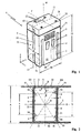
- the in Fig. 1 shown battery pack 1 consists of a cup-shaped housing 2, which is closed by a cover 33 is.
- the battery pack 1 serves as an energy source for a power tool, in particular for a hand-held implement such as a motor chainsaw, a hedge trimmer, a cut-off machine, a brushcutter, edge cutter, a pruner, a blower, a sprayer, a suction device, a Erdbohr réelle, a combination engine for multi-functional Attachments, a sweeper, a tiller, a tiller, a high-pressure cleaner, a lawn mower, a scarifier, a shredder, a wet or dry vacuum or the like.
- Working device which is preferably portable.
- the illustrated battery pack 1 has an approximately cuboidal basic shape which extends in the orthogonal spatial directions x, y and z.
- the battery pack has a vertical axis H, a width axis B and a depth axis T.
- the height 10 in the direction of the height axis H is designed such that it is greater than the width 20 in the direction of the width axis B.
- the height 10 of the battery pack 1 corresponds approximately to its 1.2 times to 2.5 times the width 20, preferably about 1.4 times its width.
- the battery pack 1 has a height 10 of about 160 mm and a width 20 of about 115 mm.
- the battery pack also has a width 20 which corresponds approximately to 1.2 times to 2.5 times the depth 30 in the direction of the depth axis T.
- the width 20 of the battery pack 1 is designed so that it corresponds approximately to 1.7 times the depth 30.
- the battery pack has a depth 30 of approximately 67 mm.
- a plurality of cells 3 are arranged, wherein in one embodiment, the cylinder axis 4 of the preferably cylindrically shaped cells 3 are aligned in the direction of the vertical axis H.
- the cylinder axes 4 of the cells 3 are parallel to the vertical axis H.
- the cells 3a may be arranged lying, so that their longitudinal axis is approximately parallel to the bottom 26 of the battery pack housing 1.
- the cylindrical shape of the battery cells shown is only an example; other cross-sectional shapes such as cuboid or the like, or a design as flat cells may be advantageous.
- a plurality of cells 3 are preferably arranged side by side in a first position; in a second position, which follows in the vertical axis H of the first layer, a further plurality of battery cells 3 are provided.
- the battery cells are rechargeable cells, z. B. battery cells such as a NiCd cell (nickel-cadmium cell), a NiMh cell (nickel-metal hydride cell), a LiIo cell (lithium-ion cell), a LiPo cell (lithium polymer cell ), a LiFePo4 cell (lithium iron phosphate cell), a lithium titanate cell or the like constructed cells.
- lithium battery cells with a cell voltage of 2 volts to 5 volts, preferably about 3.6 volts to 3.7 volts are useful.
- battery pack voltages of preferably 25 volts to 50 volts, z. B. 36 volts or 42 volts are provided. Depending on the circuit, battery pack voltages from 12 volts to 150 volts are possible.
- the performance of such Battery packs 1 is preferably in the range between 2 Ah and 10 Ah.
- the in Fig. 1 illustrated battery pack has two broad sides 21 which extend parallel to the plane spanned by the vertical axis H and the width axis B, ie in the direction of the yz plane.
- the long narrow sides 31 of the battery pack 1 extend parallel to the plane spanned by the vertical axis H and the depth axis T, thus in the yx plane.
- the end faces 11 of the battery pack extend parallel to the plane passing through the width axis B and the depth axis T, ie in the x-z plane.
- the broadsides 21 are in the embodiment according to Fig. 1 in each case two guide sections 5 in the form of guide grooves 6 which cooperate with guide means 55 in a battery compartment 7 of a housing 41 ( Fig. 2 ).
- the guide means 55 which extend in the direction of the vertical axis H, are formed in the exemplary embodiment as guide ribs 56, which engage in the guide grooves 6, which extend in the direction of the vertical axis H.
- two guide means 55 are arranged in the form of guide ribs 56 on the opposite broad sides 8 and 9 of the battery compartment 7, wherein the guide ribs 56 on one broad side 8 to the guide ribs 56 on the other broad side 9 by an offset v in the direction of the width axis B are offset.
- the guide means 55 on one broad side 8 of the battery compartment 7 a distance b from each other, which is greater than the distance a of the guide ribs 56 on the opposite Broadside 9.
- the arrangement is such that the distance a is within the distance b.
- guide grooves 24 are formed, which extend along the vertical axis H and the positionally correct positioning serve in a charger, not shown.
- a single guide groove 24 extends on a narrow side 31 from the bottom 26 into the housing cover 25 of the battery pack 1, wherein the guide groove 24 is off-center to a side center axis 17.
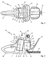
- the working device 40 a housing 41, which has housing side surfaces 42 which extend parallel to the housing longitudinal axis G and form housing longitudinal sides.
- the housing 41 has an upper and a lower housing side surface 43, wherein the lower housing side surface 43 forms a housing bottom 44.
- the upper housing side surface 43 forms a housing upper side 45.
- the housing 41 has a rear handle 46, which extends in the direction of the housing longitudinal axis G. Further, a front handle 47 is provided, which engages over the housing 41 and above a drive motor 50 which is disposed within the housing 41.
- the battery compartment 7 thus lies between the rear handle 46 and the electric drive motor 50 arranged in the housing.
- the inner partitioning of the housing 41 is provided such that between the battery compartment 7 and the front housing front side 48 inner housing space 49 is located, which receives the drive motor 50, a drive electronics for the drive motor and possibly a resource tank.
- the position of the battery compartment 7 is provided such that the drive motor 50 facing broadside 21 has a distance z to the front handle 47.
- the drive motor is arranged vertically.
- the axis of rotation 51 of the drive motor stands upright to the housing bottom 44 and drives an eccentric gear 52 for driving the hedge trimmer blades of a cutter bar 53.
- a Berckenschutz 54 is arranged between the housing end face 48 of the working device 40 and the cutter bar 53.
- the cuboid battery pack 1 is - in the embodiment of the FIGS. 3 and 4 - From above in the insertion direction 57 in the direction of the housing bottom 44 lowered into the battery compartment 7.
- the rotational position of the battery pack 1 is set about the vertical axis H by the guide portions 5 on the battery pack 1 and the guide means 55 in the battery compartment 7.
- Fig. 2 shows, is - seen in plan view of the upper end face 11 with the display means 12 and actuating means 15 - the depth axis T parallel to the housing longitudinal axis G;
- the depth axis T is in plan view Fig. 2 congruent with the longitudinal axis G.
- the battery pack 1 is received in the battery compartment 7 so that its width axis B extends transversely to the housing longitudinal axis G and its vertical axis H on the housing bottom 44 (FIGS. Fig. 4 ) stands.
- the dimensions are included made so that the narrow sides 31 of the battery pack 1 are approximately parallel and at a small distance k to the first housing side surface 42, which in the embodiment of the FIGS. 3 and 4 the housing sides are.
- the distance k is preferably in the range of 2 mm to 15 mm, preferably at the point with the greatest distance at about 9 mm.
- the faces 11 of the battery pack 1 are - like Fig. 4 shows - adjacent to other housing side surfaces 43, which are formed in the embodiment by the housing bottom 44 and the housing top 45.
- the first housing sides 42 (housing longitudinal sides) and the second housing sides 43 (housing bottom 44, housing top 45) are approximately orthogonal to each other.
- the broad sides 21 of the battery pack 1 are at a distance r of about 0.5 mm to 4 mm, preferably with a maximum distance r of 2.1 mm to the inner wall of the battery compartment 7 (FIG. Fig. 2 ).
- the arrangement is such that the vertical axis H in plan view according to Figures 2 and 3 or in plan view of the end face 11 with the display means 12 and actuating means 15, the housing longitudinal axis G of the working device 40 intersects.
- the housing longitudinal axis G is preferably the longitudinal center axis of the working device 40.
- the position of the battery pack 1, its installation orientation in the housing 41 of the working device 40 and the drive motor 50 arranged in the housing 41 are aligned with one another such that the vertical axis H of the battery pack 1 and the axis of rotation 51 of the drive motor 50 form a common plane 60; the common plane 60 is preferably perpendicular to the housing bottom 44th and forms approximately a plane of symmetry in the longitudinal direction of the working device 40.
- the housing longitudinal axis G is preferably also in the plane 60th
- the insertion position of the battery pack 1 in the battery compartment 7 is provided so that the rear end 11 in the insertion direction 57 with the display means 12 and actuating means 15 closes the battery compartment 7 and forms a partial surface of the housing side surface 43.
- the end face 11 forms with the display and / or actuating means 12, 15 is a partial surface of the housing top 45.
- the in the housing top 45 forming end face 11 arranged display means 12 and actuating means 15 are easily recognizable and easily accessible to the user.
- the vertical axis H of the battery pack 1 is inclined in the direction of the housing longitudinal axis G at an angle ⁇ to the front.
- the angle ⁇ is about 2 ° to 20 °, preferably about 15 °.
- the inclination of the vertical axis H in the direction of the front housing end face 48 is provided such that a plane 22 has a distance z from the front handle 47, the plane 22 being determined by the broad side 21 of the battery pack 1 facing the drive motor 50.
- the vertical axis H of the battery pack 1 is precisely determined by the intersection of the diagonals D1 and D2 of the end faces 11 in its position ( Fig. 2 ).
- the distance u is about 0.02 mm to 0.2 mm.
- the center of gravity 59 of the housing 41 with the drive motor 50 mounted therein, a control electronics and preferably the resource container is preferably in the plane defined by the housing high axis H and the housing longitudinal axis G plane 60; a small distance from the plane may be appropriate.
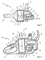
- FIGS. 5 and 6 In the embodiment of the FIGS. 5 and 6 is shown as a working device 40, a motor chain saw.
- the schematic basic structure of the implement 40 corresponds to the after FIGS. 3 and 4 Therefore, the same reference numerals are used for the same parts.
- the drive motor 50 arranged horizontally, which is why its axis of rotation 51 is approximately perpendicular to the plane 60a, which is spanned by the housing longitudinal axis G and the vertical axis H of the battery pack 1.
- the insertion of the battery pack 1 takes place in the battery compartment 7 in the insertion direction 57 from above.
- the battery pack 1 is so deep in the battery compartment 7 recorded that its upper end face 11 with the display means 12 and actuating means 15 approximately forms the housing top 45.
- a possible projection m is chosen so that the harmony of the housing top 45 is not disturbed.
- FIGS. 5 and 6 is a portable, hand-held implement shown using the example of a motor chain saw.
- the battery pack 1 is compared to the vertical 58 on the housing bottom 44 by an angle ⁇ to the rear, so inclined to the rear handle 46 back.
- the angle of inclination is preferably 2 ° to 20 °, in the embodiment shown 10 °.
- the arrangement of the battery pack 1 with its width axis B transverse to the housing longitudinal axis G of the implement 40 leads to a cheap short length, so that in a chain saw due to the constructively short lever arm, the force applied by the user feed force can not be too large. This reduces the total blockage.
- an electronic control unit 62 is arranged in addition to the electric motor 50 and the drive for the cutting set 61, which is connected to the battery pack 1, the Drive motor 50 and an actuating switch 63 is in communication.
- the actuation switch 63 is actuated via a throttle lever 64 mounted in the rear handle 46, which can be operated after depression of a throttle lock 65.
- a resource container 66 is provided in the housing space 49, the z. B. contains the chain oil for lubrication of the circulating on a guide rail saw chain.
- the center of gravity 13 of the battery pack 1 is located with a small lateral distance u to the plane defined by the vertical axis H and the housing longitudinal axis G plane 60.
- the distance u is about 0.02 mm to 0.2 mm.
- the center of gravity 59 of the device housing 41 with the internals disposed therein is in turn chosen so that it is advantageous in the plane 60a, which is spanned by the vertical axis H of the battery pack 1 and the housing longitudinal axis G; a small distance from the plane may be appropriate.
- the housing longitudinal axis G is essentially a housing longitudinal center axis.
- FIGS. 7 and 8 The embodiment of the FIGS. 7 and 8 is essentially the same as the FIGS. 5 and 6 Therefore, the same reference numerals are used for the same parts.
- the battery pack 1 laterally into the housing 41 of the working device 40th to push, which is shown in the embodiment as a motor chain saw.
- the battery pack 1 is inserted from a housing longitudinal side 67 of the housing 41, wherein the housing longitudinal side 67 extends substantially parallel to the housing longitudinal axis G.
- the vertical axis H is approximately parallel to the housing bottom 44, wherein the width axis B is approximately perpendicular to the housing bottom 44.
- the depth axis T lies - in plan view Fig. 7 - Again, parallel to the housing longitudinal axis G, preferably congruent to the housing longitudinal axis G.
- the battery pack 1 is received so deep in the battery compartment 7 that its end face 11 forms approximately the housing side surface 42 with the display means and actuating means.
- a possible projection m is chosen so that the harmony of the housing side surface 42 is not disturbed.
- the battery pack in the housing of an implement so that its width axis is aligned along the housing longitudinal axis of the implement, z. B. parallel or with the same axis with the housing longitudinal axis.
- a particularly narrow design is achieved, which may be advantageous for working in narrow areas, z. B. when relieving trees.
Landscapes
- Life Sciences & Earth Sciences (AREA)
- Engineering & Computer Science (AREA)
- Biodiversity & Conservation Biology (AREA)
- Ecology (AREA)
- Forests & Forestry (AREA)
- Environmental Sciences (AREA)
- Mechanical Engineering (AREA)
- Electrochemistry (AREA)
- General Chemical & Material Sciences (AREA)
- Chemical Kinetics & Catalysis (AREA)
- Chemical & Material Sciences (AREA)
- Battery Mounting, Suspending (AREA)
- Harvester Elements (AREA)
- Portable Power Tools In General (AREA)
Description
- Die Erfindung betrifft ein Elektroarbeitsgerät, insbesondere ein tragbares, handgeführtes Arbeitsgerät wie eine Heckenschere, eine Motorsäge oder dgl. nach dem Oberbegriff des Anspruchs 1.
- Derartige Elektrogeräte sind bekannt. Zur Aufnahme eines Akkupacks ist im Gehäuse des Elektrogerätes ein Akkuschacht ausgebildet. Ein derartiger Akkupack weist meist quaderförmige Gestalt auf und wird teilweise im Akkuschacht aufgenommen, so dass das Gehäuse des Arbeitsgerätes durch den angesetzten oder teilweise eingesetzten Akkupack unförmig ist und daher die Benutzung des Arbeitsgerätes erschwert ist.
- Aus der
DE 10 2007 017 980 A1 ist eine Elektroarbeitsgerät mit einem Gehäuse bekannt, das einen sich in Richtung einer Gehäuselängsachse erstreckenden hinteren Handgriff aufweist. Das Gerätegehäuse weist einen Gehäuseboden und erste sowie zweite Gehäuseseitenflächen auf. In dem Grätegehäuse sind ein elektrischer Antriebsmotor sowie eine Steuerelektronik zur Inbetriebnahme des Antriebsmotors aufgenommen. Im Gerätegehäuse ist ferner ein Akkuschacht zur Aufnahme eines Akkupacks vorgesehen, wobei der Akkupack etwa quaderförmige Gestalt hat und das Akkupackgehäuse sich in allen drei orthogonalen Raumrichtungen in Richtung einer Hochachse, einer Breitenachse und einer Tiefenachse erstreckt. Der Akkupack ist derart in dem Akkuschacht aufgenommen, dass sich seine Breitenachse quer zu der Gehäuselängsachse des Arbeitsgerätes erstreckt. Die Hochachse des Akkupacks steht auf dem Gehäuseboden, wobei die Stirnseiten des Akkupacks benachbart zu zweiten Gehäuseseitenflächen liegen. - Der Erfindung liegt die Aufgabe zugrunde, ein Elektroarbeitsgerät derart weiterzubilden, dass ein zum Betrieb des Gerätes eingesetzter Akkupack und die Abmessungen des Arbeitsgerätes so aufeinander abgestimmt werden, dass eine gute Handhabbarkeit des Elektrogerätes erzielt ist.
- Die Erfindung wird nach den kennzeichnenden Merkmalen des Anspruchs 1 gelöst.
- Der Akkupack liegt mit der Breitenachse quer zu der Gehäuselängsachse, wodurch sich die geringste Raumausdehnung des Akkupacks in Richtung der Gehäuselängsachse erstreckt. So kann die Baulänge eines Elektroarbeitsgerätes kurz gehalten werden und erleichtert damit dessen Führung.
- Bei Motorkettensägen wird durch die Anordnung des Akkupacks eine kurze Bauform erreicht, so dass aufgrund des nur kurzen Hebelarms die vom Benutzer aufgebrachte Vorschubkraft nicht zu groß werden kann, wodurch die Gefahr eines Blockierens des Schneidwerkzeugs im Schnitt verringert ist.
- Da die Hochachse auf dem Boden des Gerätes steht, wird im Wesentlichen die gesamte Bauhöhe eines Arbeitsgerätes genutzt, um einen Akkupack aufzunehmen.
- Nach der Erfindung hat der Akkupack eine Höhe, die größer als seine Breite ist, wobei insbesondere die Breite größer als die Tiefe des Akkupacks ist.
- In besonderer Ausbildung der Erfindung sind die langen Schmalseiten des Akkupacks unmittelbar den Gehäuselängsseiten benachbart und die Stirnseiten des Akkupacks benachbart zum Gehäuseboden und der Gehäuseoberseite vorgesehen.
- Zweckmäßige Größen für den Akkupack im Gerätegehäuse ergeben sich, wenn die Höhe des Akkupacks etwa seiner 1,2fachen bis 2,5fachen Breite entspricht und die Breite des Akkupacks etwa seiner 1,2fachen bis 2,5fachen Tiefe.
- Die Anordnung des Akkupacks im Gehäuse des Arbeitsgerätes ist so vorgesehen, dass die Hochachse des Akkupacks die Gehäuselängsachse des Arbeitsgerätes in Draufsicht schneidet. Dabei können die Hochachse des Akkupacks und die Drehachse des Antriebsmotors zweckmäßig eine gemeinsame Ebene bilden, in der vorzugsweise auch die Gehäuselängsachse liegt. Durch diese konstruktive Lage wird eine gute Gewichtsverteilung bei maximaler Raumausnutzung für einen Akkupack möglich.
- Vorzugsweise bildet eine Stirnseite des Akkupacks eine Teilfläche einer Gehäuseseite, wobei eben diese Stirnseite des Akkupacks Anzeige- und/oder Betätigungsmittel aufweisen kann, über die der Benutzer Informationen ablesen bzw. Informationen abrufen kann.
- Es hat sich als zweckmäßig erwiesen, wenn die Hochachse des Akkupacks in Richtung der Gehäuselängsachse mit einem Winkel nach vorne oder nach hinten geneigt liegt. Ein derartiger Winkel kann etwa 2° bis 20° betragen.
- Um ein einfaches Einschieben des Akkupacks zu gewährleisten ist vorgesehen, dass die dem hinteren Handgriff abgewandte Breitseite des Akkupacks eine Ebene bestimmt, die mit einem Abstand zu einem vorderen Handgriff liegt.
- Weitere Merkmale der Erfindung ergeben sich aus den weiteren Ansprüchen, der Beschreibung und der Zeichnung, in der ein nachfolgend im Einzelnen beschriebenes Ausführungsbeispiel der Erfindung dargestellt ist. Es zeigen:
- Fig. 1
- in perspektivischer Darstellung einen Akkupack,
- Fig. 2
- in schematischer Darstellung den in einen Gehäuseschacht eingesetzten Akkupack nach
Fig. 1 , - Fig. 3
- eine Draufsicht auf ein als Heckenschere ausgebildetes Elektroarbeitsgerät,
- Fig. 4
- eine schematische Seitenansicht der Heckenschere nach
Fig. 3 , - Fig. 5
- in schematischer Darstellung eine Draufsicht auf ein Elektroarbeitsgerät in Form einer Motorkettensäge,
- Fig. 6
- eine schematische Seitenansicht der Motorkettensäge nach
Fig. 5 , - Fig. 7
- eine Draufsicht auf ein Elektroarbeitsgerät entsprechend
Fig. 5 , - Fig. 8
- eine schematische Seitenansicht der Motorsäge nach
Fig. 7 . - Der in
Fig. 1 gezeigte Akkupack 1 besteht aus einem topfförmigen Gehäuse 2, welches durch einen Deckel 33 verschlossen ist. Der Akkupack 1 dient als Energiequelle für ein Elektrowerkzeug, insbesondere für ein handgeführtes Arbeitsgerät wie eine Motorkettensäge, eine Heckenschere, einen Trennschleifer, einen Freischneider, einen Kantenscheider, einen Hochentaster, ein Blasgerät, ein Sprühgerät, ein Sauggerät, ein Erdbohrgerät, ein Kombimotorgerät für multifunktionelle Vorsätze, ein Kehrgerät, eine Motorhacke, eine Bodenfräse, einen Hochdruckreiniger, einen Rasenmäher, einen Vertikutierer, einen Häcksler, einen Nass- oder Trockensauger oder dgl. Arbeitsgerät, welches vorzugsweise tragbar ist. Der dargestellte Akkupack 1 hat eine etwa quaderförmige Grundform, die sich in die orthogonalen Raumrichtungen x, y und z erstreckt. Somit weist der Akkupack eine Hochachse H, eine Breitenachse B und eine Tiefenachse T auf. Dabei ist die Höhe 10 in Richtung der Höhenachse H derart ausgeführt, dass sie größer als die Breite 20 in Richtung der Breitenachse B ist. Bevorzugt entspricht die Höhe 10 des Akkupacks 1 etwa seiner 1,2fachen bis 2,5fachen Breite 20, vorzugsweise etwa seiner 1,4fachen Breite. Zweckmäßig hat der Akkupack 1 eine Höhe 10 von ca. 160 mm und eine Breite 20 von etwa 115 mm. - Der Akkupack hat ferner eine Breite 20, die etwa seiner 1,2fachen bis 2,5fachen Tiefe 30 in Richtung der Tiefenachse T entspricht. Vorzugsweise ist die Breite 20 des Akkupacks 1 so ausgelegt, dass sie etwa der 1,7fachen Tiefe 30 entspricht. Im Ausführungsbeispiel hat der Akkupack eine Tiefe 30 von ca. 67 mm.
- Im Gehäuse 2 des Akkupacks 1 sind eine Vielzahl von Zellen 3 angeordnet, wobei in einem Ausführungsbeispiel die Zylinderachse 4 der bevorzugt zylindrisch ausgebildeten Zellen 3 in Richtung der Hochachse H ausgerichtet liegen. Die Zylinderachsen 4 der Zellen 3 liegen parallel zur Hochachse H. In einer alternativen Ausführungsform können die Zellen 3a liegend angeordnet sein, so dass ihre Längsachse etwa parallel zum Boden 26 des Akkupackgehäuses 1 liegt. Die gezeigte zylindrische Form der Akkuzellen ist nur beispielhaft; andere Querschnittsformen wie Quader oder dgl. oder eine Ausbildung als Flachzellen können vorteilhaft sein.
- Im Gehäuse 2 des Akkupacks 1 sind bevorzugt in einer ersten Lage eine Vielzahl von Zellen 3 nebeneinander stehend angeordnet; in einer zweiten Lage, die in Hochachse H der ersten Lage folgt, sind eine weitere Vielzahl von Akkuzellen 3 vorgesehen. Die Akkuzellen sind wieder aufladbare Zellen, z. B. Akkuzellen wie eine NiCd-Zelle (Nickel-Cadmium-Zelle), eine NiMh-Zelle(Nickel-Metallhydrid-Zelle), eine LiIo-Zelle (Lithium-Ionen-Zelle), eine LiPo-Zelle (Lithium-Polymer-Zelle), eine LiFePo4-Zelle (Lithium-Eisen-Phosphat-Zelle), eine Lithium-Titanat-Zelle oder dgl. aufgebaute Zellen. Insbesondere Akkuzellen auf Lithiumbasis mit einer Zellspannung von 2 Volt bis 5 Volt, vorzugsweise etwa 3,6 Volt bis 3,7 Volt sind zweckmäßig.
- Mit den verwendeten Zellen können durch entsprechende elektrische Zusammenschaltung (Reihenschaltung, Parallelschaltung) Akkupackspannungen von vorzugsweise 25 Volt bis 50 Volt, z. B. 36 Volt oder 42 Volt bereitgestellt werden. Je nach der ausgeführten Schaltung sind Akkupackspannungen von 12 Volt bis 150 Volt möglich. Die Leistung eines derartigen Akkupacks 1 liegt bevorzugt im Bereich zwischen 2 Ah und 10 Ah.
- Der in
Fig. 1 dargestellte Akkupack weist zwei Breitseiten 21 auf, die sich parallel der durch die Hochachse H und die Breitenachse B aufgespannten Ebene, also in Richtung der y-z-Ebene erstrecken. Die langen Schmalseiten 31 des Akkupacks 1 erstrecken sich parallel zu der von der Hochachse H und der Tiefenachse T aufgespannten Ebene, somit in y-x-Ebene. - Die Stirnseiten 11 des Akkupacks erstrecken sich parallel zu der durch die Breitenachse B und die Tiefenachse T erstreckenden Ebene, also in x-z-Ebene.
- In den Breitseiten 21 sind im Ausführungsbeispiel nach
Fig. 1 jeweils zwei Führungsabschnitte 5 in Form von Führungsnuten 6 ausgebildet, die mit Führungsmitteln 55 in einem Akkuschacht 7 eines Gehäuses 41 zusammenwirken (Fig. 2 ). Die Führungsmittel 55, die sich in Richtung der Hochachse H erstrecken, sind im Ausführungsbeispiel als Führungsrippen 56 ausgebildet, die in die Führungsnuten 6 eingreifen, die sich in Richtung der Hochachse H erstrecken. WieFig. 2 zeigt, sind auf den gegenüberliegenden Breitseiten 8 und 9 des Akkuschachtes 7 jeweils zwei Führungsmittel 55 in Form von Führungsrippen 56 angeordnet, wobei die Führungsrippen 56 auf der einen Breitseite 8 zu den Führungsrippen 56 auf der anderen Breitseite 9 um einen Versatz v in Richtung der Breitenachse B versetzt liegen. Bevorzugt haben die Führungsmittel 55 auf der einen Breitseite 8 des Akkuschachtes 7 einen Abstand b voneinander, der größer ist als der Abstand a der Führungsrippen 56 auf der gegenüberliegenden Breitseite 9. Die Anordnung ist so getroffen, dass der Abstand a innerhalb des Abstandes b liegt. - In den langen Schmalseiten 31 des Akkupacks 1 sind weitere Führungsnuten 24 ausgebildet, die sich längs der Hochachse H erstrecken und der lagerichtigen Positionierung in einem nicht näher dargestellten Ladegerät dienen. Eine einzelne Führungsnut 24 erstreckt sich auf einer Schmalseite 31 vom Boden 26 bis in den Gehäusedeckel 25 des Akkupacks 1, wobei die Führungsnut 24 außermittig zu einer Seitenmittelachse 17 liegt.
- Wie im Ausführungsbeispiel nach
Fig. 3 gezeigt, weist das Arbeitsgerät 40 ein Gehäuse 41 auf, welches Gehäuseseitenflächen 42 aufweist, die sich parallel zur Gehäuselängsachse G erstrecken und Gehäuselängsseiten bilden. Darüber hinaus hat das Gehäuse 41 eine obere sowie eine untere Gehäuseseitenfläche 43, wobei die untere Gehäuseseitenfläche 43 einen Gehäuseboden 44 bildet. Die obere Gehäuseseitenfläche 43 bildet eine Gehäuseoberseite 45. - Das Gehäuse 41 weist einen hinteren Handgriff 46 auf, der sich in Richtung der Gehäuselängsachse G erstreckt. Ferner ist ein vorderer Handgriff 47 vorgesehen, der das Gehäuse 41 übergreift und oberhalb eines Antriebsmotors 50 liegt, der innerhalb des Gehäuses 41 angeordnet ist. Der Akkuschacht 7 liegt somit zwischen dem hinteren Handgriff 46 und dem im Gehäuse angeordneten elektrischen Antriebsmotor 50. Die innere Aufteilung des Gehäuses 41 ist so vorgesehen, dass zwischen dem Akkuschacht 7 und der vorderen Gehäusestirnseite 48 ein innerer Gehäuseraum 49 liegt, der den Antriebsmotor 50, eine Ansteuerelektronik für den Antriebsmotor und ggf. einen Betriebsmitteltank aufnimmt. Die Lage des Akkuschachtes 7 ist derart vorgesehen, dass die dem Antriebsmotor 50 zugewandte Breitseite 21 einen Abstand z zum vorderen Handgriff 47 aufweist.
- Im Ausführungsbeispiel nach den
Figuren 3 und 4 ist eine Heckenschere gezeigt, deren Antriebsmotor stehend angeordnet ist. Die Drehachse 51 des Antriebsmotors steht aufrecht zum Gehäuseboden 44 und treibt ein Exzentergetriebe 52 zum Antrieb der Heckenscherenmesser eines Messerbalkens 53 an. - Zwischen der Gehäusestirnseite 48 des Arbeitsgerätes 40 und dem Messerbalken 53 ist ein Berührschutz 54 angeordnet.
- Der quaderförmige Akkupack 1 wird - im Ausführungsbeispiel nach den
Figuren 3 und 4 - von oben in Einschubrichtung 57 in Richtung auf den Gehäuseboden 44 in den Akkuschacht 7 abgesenkt. Dabei ist die Drehlage des Akkupacks 1 um die Hochachse H durch die Führungsabschnitte 5 am Akkupack 1 sowie die Führungsmittel 55 im Akkuschacht 7 vorgegeben. WieFig. 2 zeigt, liegt - in Draufsicht auf die obere Stirnseite 11 mit den Anzeigemitteln 12 und Betätigungsmitteln 15 gesehen - die Tiefenachse T parallel zur Gehäuselängsachse G; vorzugsweise liegt die Tiefenachse T in Draufsicht nachFig. 2 deckungsgleich mit der Längsachse G. Der Akkupack 1 ist so in dem Akkuschacht 7 aufgenommen, dass sich seine Breitenachse B quer zur Gehäuselängsachse G erstreckt und seine Hochachse H auf dem Gehäuseboden 44 (Fig. 4 ) steht. Die Abmessungen sind dabei so vorgenommen, dass die Schmalseiten 31 des Akkupacks 1 etwa parallel und mit geringem Abstand k zur ersten Gehäuseseitenfläche 42 liegen, die im Ausführungsbeispiel nach denFiguren 3 und 4 die Gehäuselängsseiten sind. Der Abstand k liegt vorzugsweise im Bereich von 2 mm bis 15 mm, vorzugsweise an der Stelle mit größtem Abstand bei etwa 9 mm. Die Stirnseiten 11 des Akkupacks 1 liegen - wieFig. 4 zeigt - benachbart zu weiteren Gehäuseseitenflächen 43, die im Ausführungsbeispiel durch den Gehäuseboden 44 und die Gehäuseoberseite 45 gebildet sind. Die ersten Gehäuseseiten 42 (Gehäuselängsseiten) und die zweiten Gehäuseseiten 43 (Gehäuseboden 44, Gehäuseoberseite 45) liegen etwa orthogonal zueinander. Die Breitseiten 21 des Akkupacks 1 liegen mit einem Abstand r von etwa 0,5 mm bis 4 mm, vorzugsweise mit einem maximalen Abstand r von 2,1 mm zur Innenwand des Akkuschachtes 7 (Fig. 2 ). - Gemäß dem Ausführungsbeispiel nach den
Figuren 3 und 4 ist die Anordnung so getroffen, dass die Hochachse H in Draufsicht gemäß denFiguren 2 und3 bzw. in Draufsicht auf die Stirnseite 11 mit den Anzeigemitteln 12 und Betätigungsmitteln 15 die Gehäuselängsachse G des Arbeitsgerätes 40 schneidet. Die Gehäuselängsachse G ist dabei bevorzugt die Längsmittelachse des Arbeitsgerätes 40. - Die Lage des Akkupacks 1, seine Einbauorientierung im Gehäuse 41 des Arbeitsgerätes 40 sowie der im Gehäuse 41 angeordnete Antriebsmotor 50 sind derart zueinander ausgerichtet, dass die Hochachse H des Akkupacks 1 und die Drehachse 51 des Antriebsmotors 50 eine gemeinsame Ebene 60 bilden; die gemeinsame Ebene 60 liegt vorzugsweise lotrecht auf dem Gehäuseboden 44 und bildet in etwa eine Symmetrieebene in Längsrichtung des Arbeitsgerätes 40.
- In bevorzugter Ausführungsform liegt die Gehäuselängsachse G bevorzugt ebenfalls in der Ebene 60.
- Die Einschublage des Akkupacks 1 in den Akkuschacht 7 ist so vorgesehen, dass die in Einschubrichtung 57 hintere Stirnseite 11 mit den Anzeigemitteln 12 und Betätigungsmitteln 15 den Akkuschacht 7 verschließt und eine Teilfläche der Gehäuseseitenfläche 43 bildet. Im gezeigten Ausführungsbeispiel bildet die Stirnseite 11 mit den Anzeige- und/oder Betätigungsmitteln 12, 15 eine Teilfläche der Gehäuseoberseite 45. Damit sind die in der die Gehäuseoberseite 45 bildenden Stirnseite 11 angeordneten Anzeigemittel 12 und Betätigungsmittel 15 für den Benutzer einfach erkennbar und leicht zugänglich.
- Im Ausführungsbeispiel nach den
Figuren 3 und 4 ist die Hochachse H des Akkupacks 1 gegenüber einer Lotrechten 58 auf den Gehäuseboden 44 geneigt angeordnet. Im Ausführungsbeispiel ist die Hochachse H des Akkupacks 1 in Richtung der Gehäuselängsachse G mit einem Winkel α nach vorne geneigt. Der Winkel α beträgt etwa 2° bis 20°, vorzugsweise etwa 15°. Die Neigung der Hochachse H in Richtung auf die vordere Gehäusestirnseite 48 ist so vorgesehen, dass eine Ebene 22 einen Abstand z zum vorderen Handgriff 47 aufweist, wobei die Ebene 22 bestimmt ist durch die dem Antriebsmotor 50 zugewandt liegende Breitseite 21 des Akkupacks 1. - Die Hochachse H des Akkupacks 1 ist durch den Schnittpunkt der Diagonalen D1 und D2 der Stirnseiten 11 in seiner Lage präzise bestimmt (
Fig. 2 ). - Die konstruktive Lage des Akkupacks 1, die durch die Gestaltung und Form des Akkuschachtes 7 im Gehäuse 41 bestimmt ist, wird zweckmäßig so gewählt, dass der Schwerpunkt 13 des Akkupacks 1 mit geringem seitlichen Abstand u zu der durch die Hochachse H und die Gehäuselängsachse G aufgespannten Ebene 60 liegt. Der Abstand u beträgt etwa 0,02 mm bis 0,2 mm. Der Schwerpunkt 59 des Gehäuses 41 mit dem darin gelagerten Antriebsmotor 50, einer Ansteuerelektronik und vorzugsweise dem Betriebsmittelbehälter liegt bevorzugt in der durch die Gehäusehochachse H und die Gehäuselängsachse G aufgespannten Ebene 60; ein geringer Abstand von der Ebene kann zweckmäßig sein.
- Im Ausführungsbeispiel nach den
Figuren 5 und 6 ist als Arbeitsgerät 40 eine Motorkettensäge gezeigt. Der schematische Grundaufbau des Arbeitsgerätes 40 entspricht dem nach denFiguren 3 und 4 , weshalb für gleiche Teile gleiche Bezugszeichen verwendet sind. - In Abweichung vom Ausführungsbeispiel einer Heckenschere nach den
Figuren 3 und 4 ist der Antriebsmotor 50 liegend angeordnet, weshalb seine Drehachse 51 etwa lotrecht auf der Ebene 60a steht, die durch die Gehäuselängsachse G und die Hochachse H des Akkupacks 1 aufgespannt ist. Auch hier erfolgt das Einschieben des Akkupacks 1 in den Akkuschacht 7 in Einschubrichtung 57 von oben. Der Akkupack 1 ist so tief im Akkuschacht 7 aufgenommen, dass seine obere Stirnseite 11 mit den Anzeigemitteln 12 und Betätigungsmitteln 15 etwa die Gehäuseoberseite 45 bildet. Ein eventueller Überstand m ist so gewählt, dass die Harmonie der Gehäuseoberseite 45 nicht gestört ist. - Durch die gewählte Anordnung des Akkupacks 1 im Gehäuse 41 des Arbeitsgerätes, im Ausführungsbeispiel eine Heckenschere, wird eine vorteilhafte Gerätebalance um den vorderen Handgriff 47 erzielt.
- Im Ausführungsbeispiel nach den
Figuren 5 und 6 ist ein tragbares, handgeführtes Arbeitsgerät am Beispiel einer Motorkettensäge gezeigt. Der Akkupack 1 ist gegenüber der Lotrechten 58 auf den Gehäuseboden 44 um einen Winkel β nach hinten, also zum hinteren Handgriff 46 hin geneigt. Der Neigungswinkel beträgt bevorzugt 2° bis 20°, im gezeigten Ausführungsbeispiel 10°. - Die Anordnung des Akkupacks 1 mit seiner Breitenachse B quer zu der Gehäuselängsachse G des Arbeitsgerätes 40 führt zu einer günstigen kurzen Baulänge, so dass bei einer Motorsäge aufgrund des konstruktiv kurzen Hebelarms die vom Benutzer aufgebrachte Vorschubkraft nicht zu groß werden kann. Dadurch ist insgesamt die Blockierneigung reduziert.
- In dem Gehäuseraum 49 zwischen dem Akkuschacht 7 und der vorderen Gehäusestirnseite 48 ist neben dem Elektromotor 50 und dem Antrieb für die Schneidgarnitur 61 eine Steuerelektronik 62 angeordnet, die mit dem Akkupack 1, dem Antriebsmotor 50 sowie einem Betätigungsschalter 63 in Verbindung steht. Der Betätigungsschalter 63 wird über einen im hinteren Handgriff 46 gelagerten Gashebel 64 betätigt, der nach Niederdrücken einer Gashebelsperre 65 bedient werden kann. Neben der Steuerelektronik 62 ist im Gehäuseraum 49 auch ein Betriebsmittelbehälter 66 vorgesehen, der z. B. das Kettenöl zur Schmierung der auf einer Führungsschiene umlaufenden Sägekette enthält.
- Der Schwerpunkt 13 des Akkupacks 1 liegt mit geringem seitlichen Abstand u zu der durch die Hochachse H und die Gehäuselängsachse G aufgespannten Ebene 60. Der Abstand u beträgt etwa 0,02 mm bis 0,2 mm. Der Schwerpunkt 59 des Gerätegehäuses 41 mit den darin angeordneten Einbauten ist wiederum so gewählt, dass er vorteilhaft in der Ebene 60a liegt, die durch die Hochachse H des Akkupacks 1 und die Gehäuselängsachse G aufgespannt ist; ein geringer Abstand von der Ebene kann zweckmäßig sein.
- Im Ausführungsbeispiel nach den
Figuren 5 und 6 ist die Gehäuselängsachse G im Wesentlichen eine Gehäuselängsmittelachse. - Das Ausführungsbeispiel nach den
Figuren 7 und 8 entspricht im Wesentlichen dem nach denFiguren 5 und 6 , weshalb für gleiche Teile gleiche Bezugszeichen verwendet sind. - In Abweichung von dem Ausführungsbeispiel nach den
Figuren 5 und 6 ist im Ausführungsbeispiel nach denFiguren 7 und 8 der Akkupack 1 seitlich in das Gehäuse 41 des Arbeitsgerätes 40 einzuschieben, welches im Ausführungsbeispiel als Motorkettensäge dargestellt ist. WieFig. 7 zeigt, wird der Akkupack 1 von einer Gehäuselängsseite 67 des Gehäuses 41 eingeschoben, wobei die Gehäuselängsseite 67 sich im Wesentlichen parallel zu der Gehäuselängsachse G erstreckt. Bei dieser Anordnung liegt die Hochachse H etwa parallel zum Gehäuseboden 44, wobei die Breitenachse B etwa lotrecht auf dem Gehäuseboden 44 steht. Die Tiefenachse T liegt - in Draufsicht nachFig. 7 - wiederum parallel zur Gehäuselängsachse G, vorzugsweise deckungsgleich zur Gehäuselängsachse G. - Der Akkupack 1 ist so tief im Akkuschacht 7 aufgenommen, dass seine Stirnseite 11 mit den Anzeigemitteln und Betätigungsmitteln etwa die Gehäuseseitenfläche 42 bildet. Ein eventueller Überstand m ist so gewählt, dass die Harmonie der Gehäuseseitenfläche 42 nicht gestört ist.
- Es kann vorteilhaft sein, in dem Gehäuse eines Arbeitsgerätes den Akkupack derart anzuordnen, dass seine Breitenachse längs der Gehäuselängsachse des Arbeitsgerätes ausgerichtet liegt, z. B. parallel oder achsengleich mit der Gehäuselängsachse. Dadurch wird eine besonders schmale Bauform erzielt, die für Arbeiten in engen Bereichen vorteilhaft sein kann, z. B. beim Entasten von Bäumen.
Claims (15)
- Elektroarbeitsgerät, insbesondere tragbares, handgeführtes Arbeitsgerät wie eine Heckenschere, eine Motorsäge, ein Trennschleifer oder dgl., mit einem Gerätegehäuse (41), das einen sich in Richtung einer Gerätegehäuselängsachse1 (G) erstreckenden hinteren Handgriff (46) aufweist, sowie mit einem Gerätegehäuseboden (44) und ersten und zweiten Gerätegehäuseseitenflächen2 (42, 43) ausgebildet ist, wobei in dem Gerätegehäuse (41) ein elektrischer Antriebsmotor (50) sowie eine Steuerelektronik (63) zur Inbetriebnahme des Antriebsmotors (50) aufgenommen ist, mit einem im Gerätegehäuse (41) ausgebildeten Akkuschacht (7) zur Aufnahme eines Akkupacks (1), wobei der Akkuschacht (7) zwischen dem hinteren Handgriff (46) und dem Antriebsmotor (50) angeordnet ist3, wobei der Akkupack (1) ein Akkupackgehäuse4 (2) mit etwa quaderförmiger Gestalt hat und sein Akkupackgehäuse (2) sich in allen drei orthogonalen Raumrichtungen (x, y, z) in Richtung einer Hochachse (H), einer Breitenachse (B) und einer Tiefenachse (T) erstreckt, wobei der Akkupack (1) eine Höhe (10), eine Breite (20) sowie eine Tiefe (30) aufweist, wobei seine Höhe (10) größer als seine Breite (20) ist5,
wobei der Akkupack (1) derart in dem Akkuschacht (7) aufgenommen ist, dass sich seine Breitenachse (B) quer zu der Gerätegehäuselängsachse (G) des Arbeitsgerätes (40) erstreckt, und wobei die Hochachse (H) auf dem Gerätegehäuseboden (44) steht und die Stirnseiten (11) des Akkupacks (1) benachbart zu den zweiten Gerätegehäuseseitenflächen (43) liegen6,
dadurch gekennzeichnet, dass die Breite (20) des Akkupacks (1) größer als seine Tiefe (30) ist7 , und dass die Schmalseiten (31) des Akkupacks (1) etwa parallel und mit geringem Abstand (k) zu einer ersten Gerätegehäuseseitenfläche (42) des Arbeitsgerätes (40) liegen. - Elektroarbeitsgerät nach Anspruch 1,
dadurch gekennzeichnet, dass die Schmalseiten (31) des Akkupacks (1) unmittelbar benachbart zu den Gerätegehäuselängsseiten (67) des Gerätegehäuses (41) liegen. - Elektroarbeitsgerät nach Anspruch 1,
dadurch gekennzeichnet, dass die Stirnseiten (11) des Akkupacks (1) benachbart zum Gerätegehäuseboden (44) und der Gerätegehäuseoberseite (45) liegen. - Elektroarbeitsgerät nach Anspruch 41,
dadurch gekennzeichnet, dass die Höhe (10) des Akkupacks (1) etwa seiner 1,2fachen bis 2,5fachen Breite (20) entspricht, vorzugsweise etwa seiner 1,4fachen Breite (20) entspricht. - Elektroarbeitsgerät nach Anspruch 41,
dadurch gekennzeichnet, dass die Breite (20) des Akkupacks (1) etwa seiner 1,2fachen bis 2,5fachen Tiefe (30) entspricht, vorzugsweise etwa seiner 1,7 fachen Tiefe (30) entspricht. - Elektroarbeitsgerät nach einem der Ansprüche 1 bis 5,
dadurch gekennzeichnet, dass die Hochachse (H) des Akkupacks (1) die Gerätegehäuselängsachse (G) des Arbeitsgerätes (40) schneidet. - Elektroarbeitsgerät nach einem der Ansprüche 1 bis 6,
dadurch gekennzeichnet, dass die Hochachse (H) des Akkupacks (1) und die Drehachse (51) des Antriebsmotors (50) eine gemeinsame Ebene (60) bilden, in der vorzugsweise auch die Gerätegehäuselängsachse (G) liegt. - Elektroarbeitsgerät nach einem der Ansprüche 1 bis 7,
dadurch gekennzeichnet, dass der Schwerpunkt (13) des Akkupacks (1) mit geringem seitlichen Abstand (u) zu der durch die Hochachse (H) und die Gerätegehäuselängsachse (G) aufgespannten Ebene (60) liegt. - Elektroarbeitsgerät nach einem der Ansprüche 1 bis 8,
dadurch gekennzeichnet, dass die eine Seitenfläche des Akkupacks (1), vorzugsweise eine Stirnseite (11), eine Teilfläche der Gerätegehäuseseitenfläche (42, 43) des Gerätegehäuses (41) bildet. - Elektroarbeitsgerät nach Anspruch 9,
dadurch gekennzeichnet, dass die Teilfläche Teil der Gerätegehäuseoberseite (45) ist. - Elektroarbeitsgerät nach einem der Ansprüche 1 bis 9,
dadurch gekennzeichnet, dass die Hochachse (H) des Akkupacks (1) zu einer Lotrechten (58) auf den Gerätegehäuseboden (44) geneigt ist. - Elektroarbeitsgerät nach Anspruch 11,
dadurch gekennzeichnet, dass die Hochachse (H) des Akkupacks (1) in Richtung der Gerätegehäuselängsachse (G) mit einem Winkel (α, β) nach vorne oder hinten geneigt liegt. - Elektroarbeitsgerät nach einem der Ansprüche 1 bis 12,
dadurch gekennzeichnet, dass in dem zwischen dem Akkuschacht (7) und der vorderen Gerätegehäusestimseite (48) liegenden Gerätegehäuseraum (49) der Antriebsmotor (50), die Steuerelektronik (62) und vorzugsweise ein Betriebsmittelbehälter (66) angeordnet sind. - Elektroarbeitsgerät nach einem der Ansprüche 1 bis 13,
dadurch gekennzeichnet, dass die dem hinteren Handgriff (46) abgewandte Breitseite (21) des Akkupacks (1) eine Ebene (22) bestimmt, die mit Abstand (z) zu einem vorderen Handgriff (47) liegt. - Elektroarbeitsgerät nach Anspruch 14,
dadurch gekennzeichnet, dass der vordere Handgriff (47) das Gerätegehäuse (41) etwa in Höhe des Antriebsmotors (50) übergreift.
Applications Claiming Priority (1)
| Application Number | Priority Date | Filing Date | Title |
|---|---|---|---|
| DE102009012175A DE102009012175A1 (de) | 2009-02-27 | 2009-02-27 | Elektroarbeitsgerät mit einem Akkupack |
Publications (3)
| Publication Number | Publication Date |
|---|---|
| EP2223780A2 EP2223780A2 (de) | 2010-09-01 |
| EP2223780A3 EP2223780A3 (de) | 2012-06-27 |
| EP2223780B1 true EP2223780B1 (de) | 2013-09-04 |
Family
ID=42154702
Family Applications (1)
| Application Number | Title | Priority Date | Filing Date |
|---|---|---|---|
| EP10001085.9A Active EP2223780B1 (de) | 2009-02-27 | 2010-02-03 | Elektroarbeitsgerät mit einem Akkupack |
Country Status (5)
| Country | Link |
|---|---|
| US (1) | US8869912B2 (de) |
| EP (1) | EP2223780B1 (de) |
| JP (1) | JP5634080B2 (de) |
| CN (1) | CN101829981B (de) |
| DE (1) | DE102009012175A1 (de) |
Cited By (2)
| Publication number | Priority date | Publication date | Assignee | Title |
|---|---|---|---|---|
| DE112015003376B4 (de) | 2014-07-22 | 2021-07-08 | Makita Corporation | Elektrisch angetriebene Kettensäge |
| DE102022116975A1 (de) | 2022-07-07 | 2024-01-18 | Andreas Stihl Ag & Co. Kg | Handgehaltenes Elektrowerkzeug und System mit einem handgehaltenen Elektrowerkzeug |
Families Citing this family (379)
| Publication number | Priority date | Publication date | Assignee | Title |
|---|---|---|---|---|
| US8286359B2 (en) * | 2002-11-19 | 2012-10-16 | Techtronic Outdoor Products Technology Limited | Battery operated chain saw |
| US20070084897A1 (en) | 2003-05-20 | 2007-04-19 | Shelton Frederick E Iv | Articulating surgical stapling instrument incorporating a two-piece e-beam firing mechanism |
| US9060770B2 (en) | 2003-05-20 | 2015-06-23 | Ethicon Endo-Surgery, Inc. | Robotically-driven surgical instrument with E-beam driver |
| US11890012B2 (en) | 2004-07-28 | 2024-02-06 | Cilag Gmbh International | Staple cartridge comprising cartridge body and attached support |
| US9072535B2 (en) | 2011-05-27 | 2015-07-07 | Ethicon Endo-Surgery, Inc. | Surgical stapling instruments with rotatable staple deployment arrangements |
| US8215531B2 (en) | 2004-07-28 | 2012-07-10 | Ethicon Endo-Surgery, Inc. | Surgical stapling instrument having a medical substance dispenser |
| US11998198B2 (en) | 2004-07-28 | 2024-06-04 | Cilag Gmbh International | Surgical stapling instrument incorporating a two-piece E-beam firing mechanism |
| US11484312B2 (en) | 2005-08-31 | 2022-11-01 | Cilag Gmbh International | Staple cartridge comprising a staple driver arrangement |
| US7669746B2 (en) | 2005-08-31 | 2010-03-02 | Ethicon Endo-Surgery, Inc. | Staple cartridges for forming staples having differing formed staple heights |
| US7934630B2 (en) | 2005-08-31 | 2011-05-03 | Ethicon Endo-Surgery, Inc. | Staple cartridges for forming staples having differing formed staple heights |
| US10159482B2 (en) | 2005-08-31 | 2018-12-25 | Ethicon Llc | Fastener cartridge assembly comprising a fixed anvil and different staple heights |
| US11246590B2 (en) | 2005-08-31 | 2022-02-15 | Cilag Gmbh International | Staple cartridge including staple drivers having different unfired heights |
| US9237891B2 (en) | 2005-08-31 | 2016-01-19 | Ethicon Endo-Surgery, Inc. | Robotically-controlled surgical stapling devices that produce formed staples having different lengths |
| US20070106317A1 (en) | 2005-11-09 | 2007-05-10 | Shelton Frederick E Iv | Hydraulically and electrically actuated articulation joints for surgical instruments |
| US8186555B2 (en) | 2006-01-31 | 2012-05-29 | Ethicon Endo-Surgery, Inc. | Motor-driven surgical cutting and fastening instrument with mechanical closure system |
| US11278279B2 (en) | 2006-01-31 | 2022-03-22 | Cilag Gmbh International | Surgical instrument assembly |
| US7845537B2 (en) | 2006-01-31 | 2010-12-07 | Ethicon Endo-Surgery, Inc. | Surgical instrument having recording capabilities |
| US11793518B2 (en) | 2006-01-31 | 2023-10-24 | Cilag Gmbh International | Powered surgical instruments with firing system lockout arrangements |
| US8820603B2 (en) | 2006-01-31 | 2014-09-02 | Ethicon Endo-Surgery, Inc. | Accessing data stored in a memory of a surgical instrument |
| US20110290856A1 (en) | 2006-01-31 | 2011-12-01 | Ethicon Endo-Surgery, Inc. | Robotically-controlled surgical instrument with force-feedback capabilities |
| US8708213B2 (en) | 2006-01-31 | 2014-04-29 | Ethicon Endo-Surgery, Inc. | Surgical instrument having a feedback system |
| US7753904B2 (en) | 2006-01-31 | 2010-07-13 | Ethicon Endo-Surgery, Inc. | Endoscopic surgical instrument with a handle that can articulate with respect to the shaft |
| US20120292367A1 (en) | 2006-01-31 | 2012-11-22 | Ethicon Endo-Surgery, Inc. | Robotically-controlled end effector |
| US11224427B2 (en) | 2006-01-31 | 2022-01-18 | Cilag Gmbh International | Surgical stapling system including a console and retraction assembly |
| US8992422B2 (en) | 2006-03-23 | 2015-03-31 | Ethicon Endo-Surgery, Inc. | Robotically-controlled endoscopic accessory channel |
| DE102006018072B4 (de) * | 2006-04-10 | 2016-08-11 | Andreas Stihl Ag & Co. Kg | Heckenschere |
| US8322455B2 (en) | 2006-06-27 | 2012-12-04 | Ethicon Endo-Surgery, Inc. | Manually driven surgical cutting and fastening instrument |
| US10568652B2 (en) | 2006-09-29 | 2020-02-25 | Ethicon Llc | Surgical staples having attached drivers of different heights and stapling instruments for deploying the same |
| US11980366B2 (en) | 2006-10-03 | 2024-05-14 | Cilag Gmbh International | Surgical instrument |
| US11291441B2 (en) | 2007-01-10 | 2022-04-05 | Cilag Gmbh International | Surgical instrument with wireless communication between control unit and remote sensor |
| US8684253B2 (en) | 2007-01-10 | 2014-04-01 | Ethicon Endo-Surgery, Inc. | Surgical instrument with wireless communication between a control unit of a robotic system and remote sensor |
| US8632535B2 (en) | 2007-01-10 | 2014-01-21 | Ethicon Endo-Surgery, Inc. | Interlock and surgical instrument including same |
| US20080169332A1 (en) | 2007-01-11 | 2008-07-17 | Shelton Frederick E | Surgical stapling device with a curved cutting member |
| US8727197B2 (en) | 2007-03-15 | 2014-05-20 | Ethicon Endo-Surgery, Inc. | Staple cartridge cavity configuration with cooperative surgical staple |
| US8931682B2 (en) | 2007-06-04 | 2015-01-13 | Ethicon Endo-Surgery, Inc. | Robotically-controlled shaft based rotary drive systems for surgical instruments |
| US11857181B2 (en) | 2007-06-04 | 2024-01-02 | Cilag Gmbh International | Robotically-controlled shaft based rotary drive systems for surgical instruments |
| US7753245B2 (en) | 2007-06-22 | 2010-07-13 | Ethicon Endo-Surgery, Inc. | Surgical stapling instruments |
| US11849941B2 (en) | 2007-06-29 | 2023-12-26 | Cilag Gmbh International | Staple cartridge having staple cavities extending at a transverse angle relative to a longitudinal cartridge axis |
| US7866527B2 (en) | 2008-02-14 | 2011-01-11 | Ethicon Endo-Surgery, Inc. | Surgical stapling apparatus with interlockable firing system |
| RU2493788C2 (ru) | 2008-02-14 | 2013-09-27 | Этикон Эндо-Серджери, Инк. | Хирургический режущий и крепежный инструмент, имеющий радиочастотные электроды |
| US8573465B2 (en) | 2008-02-14 | 2013-11-05 | Ethicon Endo-Surgery, Inc. | Robotically-controlled surgical end effector system with rotary actuated closure systems |
| US8636736B2 (en) | 2008-02-14 | 2014-01-28 | Ethicon Endo-Surgery, Inc. | Motorized surgical cutting and fastening instrument |
| US9179912B2 (en) | 2008-02-14 | 2015-11-10 | Ethicon Endo-Surgery, Inc. | Robotically-controlled motorized surgical cutting and fastening instrument |
| US11986183B2 (en) | 2008-02-14 | 2024-05-21 | Cilag Gmbh International | Surgical cutting and fastening instrument comprising a plurality of sensors to measure an electrical parameter |
| US7819298B2 (en) | 2008-02-14 | 2010-10-26 | Ethicon Endo-Surgery, Inc. | Surgical stapling apparatus with control features operable with one hand |
| US20130153641A1 (en) | 2008-02-15 | 2013-06-20 | Ethicon Endo-Surgery, Inc. | Releasable layer of material and surgical end effector having the same |
| US8210411B2 (en) | 2008-09-23 | 2012-07-03 | Ethicon Endo-Surgery, Inc. | Motor-driven surgical cutting instrument |
| US11648005B2 (en) | 2008-09-23 | 2023-05-16 | Cilag Gmbh International | Robotically-controlled motorized surgical instrument with an end effector |
| US9005230B2 (en) | 2008-09-23 | 2015-04-14 | Ethicon Endo-Surgery, Inc. | Motorized surgical instrument |
| US9386983B2 (en) | 2008-09-23 | 2016-07-12 | Ethicon Endo-Surgery, Llc | Robotically-controlled motorized surgical instrument |
| US8608045B2 (en) | 2008-10-10 | 2013-12-17 | Ethicon Endo-Sugery, Inc. | Powered surgical cutting and stapling apparatus with manually retractable firing system |
| DE102008064007A1 (de) * | 2008-12-19 | 2010-06-24 | Andreas Stihl Ag & Co. Kg | Heckenschere |
| US8517239B2 (en) | 2009-02-05 | 2013-08-27 | Ethicon Endo-Surgery, Inc. | Surgical stapling instrument comprising a magnetic element driver |
| DE102009012178B4 (de) * | 2009-02-27 | 2019-07-04 | Andreas Stihl Ag & Co. Kg | Akkubetriebenes, handgeführtes Arbeitsgerät |
| JP5396643B2 (ja) * | 2009-03-05 | 2014-01-22 | マックス株式会社 | 携帯用切断機 |
| US8851354B2 (en) | 2009-12-24 | 2014-10-07 | Ethicon Endo-Surgery, Inc. | Surgical cutting instrument that analyzes tissue thickness |
| US8220688B2 (en) | 2009-12-24 | 2012-07-17 | Ethicon Endo-Surgery, Inc. | Motor-driven surgical cutting instrument with electric actuator directional control assembly |
| WO2011110188A1 (en) * | 2010-03-06 | 2011-09-15 | Husqvarna Ab | Power tool having protection housing for battery |
| WO2012002860A1 (en) | 2010-07-02 | 2012-01-05 | Husqvarna Ab | Battery powered tool |
| WO2011110189A1 (en) * | 2010-03-06 | 2011-09-15 | Husqvarna Ab | Battery driven electric tool |
| US8783543B2 (en) | 2010-07-30 | 2014-07-22 | Ethicon Endo-Surgery, Inc. | Tissue acquisition arrangements and methods for surgical stapling devices |
| DE102010045993A1 (de) * | 2010-09-18 | 2012-03-22 | Andreas Stihl Ag & Co. Kg | Handgeführtes Arbeitsgerät mit einem elektrischen Antriebsmotor |
| DE102010045994A1 (de) * | 2010-09-18 | 2012-03-22 | Andreas Stihl Ag & Co. Kg | Handgeführtes Arbeitsgerät |
| US9629814B2 (en) | 2010-09-30 | 2017-04-25 | Ethicon Endo-Surgery, Llc | Tissue thickness compensator configured to redistribute compressive forces |
| US10405854B2 (en) | 2010-09-30 | 2019-09-10 | Ethicon Llc | Surgical stapling cartridge with layer retention features |
| US9241714B2 (en) | 2011-04-29 | 2016-01-26 | Ethicon Endo-Surgery, Inc. | Tissue thickness compensator and method for making the same |
| US9113865B2 (en) | 2010-09-30 | 2015-08-25 | Ethicon Endo-Surgery, Inc. | Staple cartridge comprising a layer |
| US9320523B2 (en) | 2012-03-28 | 2016-04-26 | Ethicon Endo-Surgery, Llc | Tissue thickness compensator comprising tissue ingrowth features |
| US11812965B2 (en) | 2010-09-30 | 2023-11-14 | Cilag Gmbh International | Layer of material for a surgical end effector |
| US12213666B2 (en) | 2010-09-30 | 2025-02-04 | Cilag Gmbh International | Tissue thickness compensator comprising layers |
| US11298125B2 (en) | 2010-09-30 | 2022-04-12 | Cilag Gmbh International | Tissue stapler having a thickness compensator |
| US11925354B2 (en) | 2010-09-30 | 2024-03-12 | Cilag Gmbh International | Staple cartridge comprising staples positioned within a compressible portion thereof |
| US10945731B2 (en) | 2010-09-30 | 2021-03-16 | Ethicon Llc | Tissue thickness compensator comprising controlled release and expansion |
| US8695866B2 (en) | 2010-10-01 | 2014-04-15 | Ethicon Endo-Surgery, Inc. | Surgical instrument having a power control circuit |
| JP5618784B2 (ja) * | 2010-11-26 | 2014-11-05 | 株式会社マキタ | 切断機 |
| JP5752435B2 (ja) * | 2011-02-18 | 2015-07-22 | リョービ株式会社 | 刈払機 |
| USD663182S1 (en) | 2011-03-04 | 2012-07-10 | Blount, Inc. | Saw body |
| BR112013027794B1 (pt) | 2011-04-29 | 2020-12-15 | Ethicon Endo-Surgery, Inc | Conjunto de cartucho de grampos |
| US11207064B2 (en) | 2011-05-27 | 2021-12-28 | Cilag Gmbh International | Automated end effector component reloading system for use with a robotic system |
| DE102011080309A1 (de) * | 2011-08-03 | 2013-02-07 | Robert Bosch Gmbh | Energieversorgungsvorrichtung |
| US10213936B2 (en) | 2011-08-26 | 2019-02-26 | Husqvarna Ab | Battery powered rear handle chain saw |
| CN102398079A (zh) * | 2011-11-18 | 2012-04-04 | 浙江亚特电器有限公司 | 蓄电池驱动的链锯 |
| CN102554882B (zh) * | 2012-02-28 | 2015-08-12 | 南京德朔实业有限公司 | 手持式工具 |
| MX350846B (es) | 2012-03-28 | 2017-09-22 | Ethicon Endo Surgery Inc | Compensador de grosor de tejido que comprende cápsulas que definen un ambiente de baja presión. |
| MX358135B (es) | 2012-03-28 | 2018-08-06 | Ethicon Endo Surgery Inc | Compensador de grosor de tejido que comprende una pluralidad de capas. |
| DE102012104538A1 (de) * | 2012-05-25 | 2013-11-28 | Gustav Klauke Gmbh | Werkzeug |
| DE102012209919A1 (de) * | 2012-06-13 | 2013-12-19 | Hilti Aktiengesellschaft | Handwerkzeugmaschine |
| US9101358B2 (en) | 2012-06-15 | 2015-08-11 | Ethicon Endo-Surgery, Inc. | Articulatable surgical instrument comprising a firing drive |
| US9226751B2 (en) | 2012-06-28 | 2016-01-05 | Ethicon Endo-Surgery, Inc. | Surgical instrument system including replaceable end effectors |
| US9289256B2 (en) | 2012-06-28 | 2016-03-22 | Ethicon Endo-Surgery, Llc | Surgical end effectors having angled tissue-contacting surfaces |
| BR112014032776B1 (pt) | 2012-06-28 | 2021-09-08 | Ethicon Endo-Surgery, Inc | Sistema de instrumento cirúrgico e kit cirúrgico para uso com um sistema de instrumento cirúrgico |
| US11197671B2 (en) | 2012-06-28 | 2021-12-14 | Cilag Gmbh International | Stapling assembly comprising a lockout |
| JP6290201B2 (ja) | 2012-06-28 | 2018-03-07 | エシコン・エンド−サージェリィ・インコーポレイテッドEthicon Endo−Surgery,Inc. | 空クリップカートリッジ用のロックアウト |
| US9282974B2 (en) | 2012-06-28 | 2016-03-15 | Ethicon Endo-Surgery, Llc | Empty clip cartridge lockout |
| US20140001231A1 (en) | 2012-06-28 | 2014-01-02 | Ethicon Endo-Surgery, Inc. | Firing system lockout arrangements for surgical instruments |
| US12383267B2 (en) | 2012-06-28 | 2025-08-12 | Cilag Gmbh International | Robotically powered surgical device with manually-actuatable reversing system |
| JP6032400B2 (ja) * | 2012-08-15 | 2016-11-30 | 日立工機株式会社 | チェーンソー |
| JP6070072B2 (ja) | 2012-10-31 | 2017-02-01 | 日立工機株式会社 | 動力工具 |
| JP6098117B2 (ja) * | 2012-10-31 | 2017-03-22 | 日立工機株式会社 | 携帯用工具 |
| JP2014147590A (ja) * | 2013-02-01 | 2014-08-21 | Makita Corp | 手持ち式のクリーナ |
| JP2014148024A (ja) * | 2013-02-01 | 2014-08-21 | Makita Corp | 研削工具 |
| US20150328764A1 (en) | 2013-02-01 | 2015-11-19 | Makita Corporation | Power tool |
| RU2669463C2 (ru) | 2013-03-01 | 2018-10-11 | Этикон Эндо-Серджери, Инк. | Хирургический инструмент с мягким упором |
| MX368026B (es) | 2013-03-01 | 2019-09-12 | Ethicon Endo Surgery Inc | Instrumento quirúrgico articulable con vías conductoras para la comunicación de la señal. |
| US9629629B2 (en) | 2013-03-14 | 2017-04-25 | Ethicon Endo-Surgey, LLC | Control systems for surgical instruments |
| JP2014176567A (ja) * | 2013-03-15 | 2014-09-25 | Makita Corp | クリーナ |
| BR112015026109B1 (pt) | 2013-04-16 | 2022-02-22 | Ethicon Endo-Surgery, Inc | Instrumento cirúrgico |
| US9801626B2 (en) | 2013-04-16 | 2017-10-31 | Ethicon Llc | Modular motor driven surgical instruments with alignment features for aligning rotary drive shafts with surgical end effector shafts |
| CN103299835B (zh) * | 2013-05-30 | 2014-12-24 | 江苏苏美达五金工具有限公司 | 一种便携式电动工具 |
| US20150053737A1 (en) | 2013-08-23 | 2015-02-26 | Ethicon Endo-Surgery, Inc. | End effector detection systems for surgical instruments |
| MX369362B (es) | 2013-08-23 | 2019-11-06 | Ethicon Endo Surgery Llc | Dispositivos de retraccion de miembros de disparo para instrumentos quirurgicos electricos. |
| US10013049B2 (en) | 2014-03-26 | 2018-07-03 | Ethicon Llc | Power management through sleep options of segmented circuit and wake up control |
| US12232723B2 (en) | 2014-03-26 | 2025-02-25 | Cilag Gmbh International | Systems and methods for controlling a segmented circuit |
| US9750499B2 (en) | 2014-03-26 | 2017-09-05 | Ethicon Llc | Surgical stapling instrument system |
| BR112016021943B1 (pt) | 2014-03-26 | 2022-06-14 | Ethicon Endo-Surgery, Llc | Instrumento cirúrgico para uso por um operador em um procedimento cirúrgico |
| JP6328473B2 (ja) * | 2014-04-09 | 2018-05-23 | 株式会社マキタ | 電動工具 |
| JP6532889B2 (ja) | 2014-04-16 | 2019-06-19 | エシコン エルエルシーEthicon LLC | 締結具カートリッジ組立体及びステープル保持具カバー配置構成 |
| US10327764B2 (en) | 2014-09-26 | 2019-06-25 | Ethicon Llc | Method for creating a flexible staple line |
| CN106456176B (zh) | 2014-04-16 | 2019-06-28 | 伊西康内外科有限责任公司 | 包括具有不同构型的延伸部的紧固件仓 |
| CN106456158B (zh) | 2014-04-16 | 2019-02-05 | 伊西康内外科有限责任公司 | 包括非一致紧固件的紧固件仓 |
| US20150297223A1 (en) | 2014-04-16 | 2015-10-22 | Ethicon Endo-Surgery, Inc. | Fastener cartridges including extensions having different configurations |
| JP6345523B2 (ja) * | 2014-07-23 | 2018-06-20 | 株式会社やまびこ | バッテリ駆動式作業機 |
| US11311294B2 (en) | 2014-09-05 | 2022-04-26 | Cilag Gmbh International | Powered medical device including measurement of closure state of jaws |
| BR112017004361B1 (pt) | 2014-09-05 | 2023-04-11 | Ethicon Llc | Sistema eletrônico para um instrumento cirúrgico |
| US9724094B2 (en) | 2014-09-05 | 2017-08-08 | Ethicon Llc | Adjunct with integrated sensors to quantify tissue compression |
| US10105142B2 (en) | 2014-09-18 | 2018-10-23 | Ethicon Llc | Surgical stapler with plurality of cutting elements |
| US11523821B2 (en) | 2014-09-26 | 2022-12-13 | Cilag Gmbh International | Method for creating a flexible staple line |
| JP6648119B2 (ja) | 2014-09-26 | 2020-02-14 | エシコン エルエルシーEthicon LLC | 外科ステープル留めバットレス及び付属物材料 |
| US9924944B2 (en) | 2014-10-16 | 2018-03-27 | Ethicon Llc | Staple cartridge comprising an adjunct material |
| US11141153B2 (en) | 2014-10-29 | 2021-10-12 | Cilag Gmbh International | Staple cartridges comprising driver arrangements |
| US10517594B2 (en) | 2014-10-29 | 2019-12-31 | Ethicon Llc | Cartridge assemblies for surgical staplers |
| US9844376B2 (en) | 2014-11-06 | 2017-12-19 | Ethicon Llc | Staple cartridge comprising a releasable adjunct material |
| US10736636B2 (en) | 2014-12-10 | 2020-08-11 | Ethicon Llc | Articulatable surgical instrument system |
| RU2703684C2 (ru) | 2014-12-18 | 2019-10-21 | ЭТИКОН ЭНДО-СЕРДЖЕРИ, ЭлЭлСи | Хирургический инструмент с упором, который выполнен с возможностью избирательного перемещения относительно кассеты со скобами вокруг дискретной неподвижной оси |
| US9987000B2 (en) | 2014-12-18 | 2018-06-05 | Ethicon Llc | Surgical instrument assembly comprising a flexible articulation system |
| US10245027B2 (en) | 2014-12-18 | 2019-04-02 | Ethicon Llc | Surgical instrument with an anvil that is selectively movable about a discrete non-movable axis relative to a staple cartridge |
| US9844375B2 (en) | 2014-12-18 | 2017-12-19 | Ethicon Llc | Drive arrangements for articulatable surgical instruments |
| US10085748B2 (en) | 2014-12-18 | 2018-10-02 | Ethicon Llc | Locking arrangements for detachable shaft assemblies with articulatable surgical end effectors |
| US9844374B2 (en) | 2014-12-18 | 2017-12-19 | Ethicon Llc | Surgical instrument systems comprising an articulatable end effector and means for adjusting the firing stroke of a firing member |
| US11154301B2 (en) | 2015-02-27 | 2021-10-26 | Cilag Gmbh International | Modular stapling assembly |
| US10548504B2 (en) | 2015-03-06 | 2020-02-04 | Ethicon Llc | Overlaid multi sensor radio frequency (RF) electrode system to measure tissue compression |
| US9808246B2 (en) | 2015-03-06 | 2017-11-07 | Ethicon Endo-Surgery, Llc | Method of operating a powered surgical instrument |
| US9993248B2 (en) | 2015-03-06 | 2018-06-12 | Ethicon Endo-Surgery, Llc | Smart sensors with local signal processing |
| US10441279B2 (en) | 2015-03-06 | 2019-10-15 | Ethicon Llc | Multiple level thresholds to modify operation of powered surgical instruments |
| JP2020121162A (ja) | 2015-03-06 | 2020-08-13 | エシコン エルエルシーEthicon LLC | 測定の安定性要素、クリープ要素、及び粘弾性要素を決定するためのセンサデータの時間依存性評価 |
| US9668427B2 (en) | 2015-03-25 | 2017-06-06 | Black & Decker Inc. | Battery-powered blower |
| US10390825B2 (en) | 2015-03-31 | 2019-08-27 | Ethicon Llc | Surgical instrument with progressive rotary drive systems |
| DE102015012043A1 (de) * | 2015-09-15 | 2017-03-16 | Andreas Stihl Ag & Co. Kg | Verfahren zur Inbetriebnahme eines handgeführten Arbeitsgerätes mit einem Elektromotor |
| US10238386B2 (en) | 2015-09-23 | 2019-03-26 | Ethicon Llc | Surgical stapler having motor control based on an electrical parameter related to a motor current |
| US10105139B2 (en) | 2015-09-23 | 2018-10-23 | Ethicon Llc | Surgical stapler having downstream current-based motor control |
| US10299878B2 (en) | 2015-09-25 | 2019-05-28 | Ethicon Llc | Implantable adjunct systems for determining adjunct skew |
| US10736633B2 (en) | 2015-09-30 | 2020-08-11 | Ethicon Llc | Compressible adjunct with looping members |
| US10172620B2 (en) | 2015-09-30 | 2019-01-08 | Ethicon Llc | Compressible adjuncts with bonding nodes |
| US11890015B2 (en) | 2015-09-30 | 2024-02-06 | Cilag Gmbh International | Compressible adjunct with crossing spacer fibers |
| US10292704B2 (en) | 2015-12-30 | 2019-05-21 | Ethicon Llc | Mechanisms for compensating for battery pack failure in powered surgical instruments |
| US10265068B2 (en) | 2015-12-30 | 2019-04-23 | Ethicon Llc | Surgical instruments with separable motors and motor control circuits |
| US11213293B2 (en) | 2016-02-09 | 2022-01-04 | Cilag Gmbh International | Articulatable surgical instruments with single articulation link arrangements |
| BR112018016098B1 (pt) | 2016-02-09 | 2023-02-23 | Ethicon Llc | Instrumento cirúrgico |
| US10448948B2 (en) | 2016-02-12 | 2019-10-22 | Ethicon Llc | Mechanisms for compensating for drivetrain failure in powered surgical instruments |
| US11224426B2 (en) | 2016-02-12 | 2022-01-18 | Cilag Gmbh International | Mechanisms for compensating for drivetrain failure in powered surgical instruments |
| US10357247B2 (en) | 2016-04-15 | 2019-07-23 | Ethicon Llc | Surgical instrument with multiple program responses during a firing motion |
| US10426467B2 (en) | 2016-04-15 | 2019-10-01 | Ethicon Llc | Surgical instrument with detection sensors |
| US11607239B2 (en) | 2016-04-15 | 2023-03-21 | Cilag Gmbh International | Systems and methods for controlling a surgical stapling and cutting instrument |
| US11179150B2 (en) | 2016-04-15 | 2021-11-23 | Cilag Gmbh International | Systems and methods for controlling a surgical stapling and cutting instrument |
| US10456137B2 (en) | 2016-04-15 | 2019-10-29 | Ethicon Llc | Staple formation detection mechanisms |
| US10828028B2 (en) | 2016-04-15 | 2020-11-10 | Ethicon Llc | Surgical instrument with multiple program responses during a firing motion |
| US10492783B2 (en) | 2016-04-15 | 2019-12-03 | Ethicon, Llc | Surgical instrument with improved stop/start control during a firing motion |
| US20170296173A1 (en) | 2016-04-18 | 2017-10-19 | Ethicon Endo-Surgery, Llc | Method for operating a surgical instrument |
| US11317917B2 (en) | 2016-04-18 | 2022-05-03 | Cilag Gmbh International | Surgical stapling system comprising a lockable firing assembly |
| US10433840B2 (en) | 2016-04-18 | 2019-10-08 | Ethicon Llc | Surgical instrument comprising a replaceable cartridge jaw |
| US10500000B2 (en) | 2016-08-16 | 2019-12-10 | Ethicon Llc | Surgical tool with manual control of end effector jaws |
| US10632589B2 (en) | 2016-08-29 | 2020-04-28 | Black & Decker Inc. | Power tool |
| CN106386200B (zh) * | 2016-10-17 | 2022-07-26 | 福建诚德农业机械有限公司 | 一种植物除芽器 |
| US10918385B2 (en) | 2016-12-21 | 2021-02-16 | Ethicon Llc | Surgical system comprising a firing member rotatable into an articulation state to articulate an end effector of the surgical system |
| US10568626B2 (en) | 2016-12-21 | 2020-02-25 | Ethicon Llc | Surgical instruments with jaw opening features for increasing a jaw opening distance |
| US20180168615A1 (en) | 2016-12-21 | 2018-06-21 | Ethicon Endo-Surgery, Llc | Method of deforming staples from two different types of staple cartridges with the same surgical stapling instrument |
| US10758230B2 (en) | 2016-12-21 | 2020-09-01 | Ethicon Llc | Surgical instrument with primary and safety processors |
| CN110099619B (zh) | 2016-12-21 | 2022-07-15 | 爱惜康有限责任公司 | 用于外科端部执行器和可替换工具组件的闭锁装置 |
| MX2019007311A (es) | 2016-12-21 | 2019-11-18 | Ethicon Llc | Sistemas de engrapado quirurgico. |
| CN110114014B (zh) | 2016-12-21 | 2022-08-09 | 爱惜康有限责任公司 | 包括端部执行器闭锁件和击发组件闭锁件的外科器械系统 |
| JP7010957B2 (ja) | 2016-12-21 | 2022-01-26 | エシコン エルエルシー | ロックアウトを備えるシャフトアセンブリ |
| JP7010956B2 (ja) | 2016-12-21 | 2022-01-26 | エシコン エルエルシー | 組織をステープル留めする方法 |
| US11090048B2 (en) | 2016-12-21 | 2021-08-17 | Cilag Gmbh International | Method for resetting a fuse of a surgical instrument shaft |
| US10639035B2 (en) | 2016-12-21 | 2020-05-05 | Ethicon Llc | Surgical stapling instruments and replaceable tool assemblies thereof |
| US20180168623A1 (en) | 2016-12-21 | 2018-06-21 | Ethicon Endo-Surgery, Llc | Surgical stapling systems |
| JP2020501815A (ja) | 2016-12-21 | 2020-01-23 | エシコン エルエルシーEthicon LLC | 外科用ステープル留めシステム |
| US10617414B2 (en) | 2016-12-21 | 2020-04-14 | Ethicon Llc | Closure member arrangements for surgical instruments |
| US11419606B2 (en) | 2016-12-21 | 2022-08-23 | Cilag Gmbh International | Shaft assembly comprising a clutch configured to adapt the output of a rotary firing member to two different systems |
| CN206445291U (zh) * | 2017-01-22 | 2017-08-29 | 南京德朔实业有限公司 | 用于切割的动力工具 |
| DE102017002094A1 (de) * | 2017-03-04 | 2018-09-06 | Andreas Stihl Ag & Co. Kg | Elektrisches Arbeitsgerät mit Vibrationsentkopplung |
| US11517325B2 (en) | 2017-06-20 | 2022-12-06 | Cilag Gmbh International | Closed loop feedback control of motor velocity of a surgical stapling and cutting instrument based on measured displacement distance traveled over a specified time interval |
| US12490980B2 (en) | 2017-06-20 | 2025-12-09 | Cilag Gmbh International | Surgical instrument having controllable articulation velocity |
| US11653914B2 (en) | 2017-06-20 | 2023-05-23 | Cilag Gmbh International | Systems and methods for controlling motor velocity of a surgical stapling and cutting instrument according to articulation angle of end effector |
| US10881399B2 (en) | 2017-06-20 | 2021-01-05 | Ethicon Llc | Techniques for adaptive control of motor velocity of a surgical stapling and cutting instrument |
| US10779820B2 (en) | 2017-06-20 | 2020-09-22 | Ethicon Llc | Systems and methods for controlling motor speed according to user input for a surgical instrument |
| US11382638B2 (en) | 2017-06-20 | 2022-07-12 | Cilag Gmbh International | Closed loop feedback control of motor velocity of a surgical stapling and cutting instrument based on measured time over a specified displacement distance |
| US10307170B2 (en) | 2017-06-20 | 2019-06-04 | Ethicon Llc | Method for closed loop control of motor velocity of a surgical stapling and cutting instrument |
| US10993716B2 (en) | 2017-06-27 | 2021-05-04 | Ethicon Llc | Surgical anvil arrangements |
| US11266405B2 (en) | 2017-06-27 | 2022-03-08 | Cilag Gmbh International | Surgical anvil manufacturing methods |
| US11090049B2 (en) | 2017-06-27 | 2021-08-17 | Cilag Gmbh International | Staple forming pocket arrangements |
| US11324503B2 (en) | 2017-06-27 | 2022-05-10 | Cilag Gmbh International | Surgical firing member arrangements |
| US20190000461A1 (en) | 2017-06-28 | 2019-01-03 | Ethicon Llc | Surgical cutting and fastening devices with pivotable anvil with a tissue locating arrangement in close proximity to an anvil pivot axis |
| US11259805B2 (en) | 2017-06-28 | 2022-03-01 | Cilag Gmbh International | Surgical instrument comprising firing member supports |
| US10765427B2 (en) | 2017-06-28 | 2020-09-08 | Ethicon Llc | Method for articulating a surgical instrument |
| EP4070740B1 (de) | 2017-06-28 | 2025-03-26 | Cilag GmbH International | Chirurgisches instrument mit selektiv betätigbaren drehbaren kopplern |
| US11246592B2 (en) | 2017-06-28 | 2022-02-15 | Cilag Gmbh International | Surgical instrument comprising an articulation system lockable to a frame |
| USD906355S1 (en) | 2017-06-28 | 2020-12-29 | Ethicon Llc | Display screen or portion thereof with a graphical user interface for a surgical instrument |
| US11000279B2 (en) | 2017-06-28 | 2021-05-11 | Ethicon Llc | Surgical instrument comprising an articulation system ratio |
| BR112019027065B1 (pt) | 2017-06-28 | 2023-12-26 | Ethicon Llc | Instrumento cirúrgico e sistema cirúrgico |
| US11564686B2 (en) | 2017-06-28 | 2023-01-31 | Cilag Gmbh International | Surgical shaft assemblies with flexible interfaces |
| US10932772B2 (en) | 2017-06-29 | 2021-03-02 | Ethicon Llc | Methods for closed loop velocity control for robotic surgical instrument |
| US11944300B2 (en) | 2017-08-03 | 2024-04-02 | Cilag Gmbh International | Method for operating a surgical system bailout |
| US11304695B2 (en) | 2017-08-03 | 2022-04-19 | Cilag Gmbh International | Surgical system shaft interconnection |
| US11974742B2 (en) | 2017-08-03 | 2024-05-07 | Cilag Gmbh International | Surgical system comprising an articulation bailout |
| US11471155B2 (en) | 2017-08-03 | 2022-10-18 | Cilag Gmbh International | Surgical system bailout |
| US11358268B2 (en) * | 2017-09-27 | 2022-06-14 | Globe (jiangsu) Co., Ltd. | Battery compartment for power tools |
| US11399829B2 (en) | 2017-09-29 | 2022-08-02 | Cilag Gmbh International | Systems and methods of initiating a power shutdown mode for a surgical instrument |
| US10743872B2 (en) | 2017-09-29 | 2020-08-18 | Ethicon Llc | System and methods for controlling a display of a surgical instrument |
| JP2018001407A (ja) * | 2017-10-11 | 2018-01-11 | 株式会社マキタ | 手持式電動切断機 |
| WO2019079560A1 (en) | 2017-10-20 | 2019-04-25 | Milwaukee Electric Tool Corporation | PERCUSSION TOOL |
| US11134944B2 (en) | 2017-10-30 | 2021-10-05 | Cilag Gmbh International | Surgical stapler knife motion controls |
| US10842490B2 (en) | 2017-10-31 | 2020-11-24 | Ethicon Llc | Cartridge body design with force reduction based on firing completion |
| US10779826B2 (en) | 2017-12-15 | 2020-09-22 | Ethicon Llc | Methods of operating surgical end effectors |
| US10835330B2 (en) | 2017-12-19 | 2020-11-17 | Ethicon Llc | Method for determining the position of a rotatable jaw of a surgical instrument attachment assembly |
| US11751867B2 (en) | 2017-12-21 | 2023-09-12 | Cilag Gmbh International | Surgical instrument comprising sequenced systems |
| US12336705B2 (en) | 2017-12-21 | 2025-06-24 | Cilag Gmbh International | Continuous use self-propelled stapling instrument |
| US11311290B2 (en) | 2017-12-21 | 2022-04-26 | Cilag Gmbh International | Surgical instrument comprising an end effector dampener |
| US11059155B2 (en) | 2018-01-26 | 2021-07-13 | Milwaukee Electric Tool Corporation | Percussion tool |
| US11291440B2 (en) | 2018-08-20 | 2022-04-05 | Cilag Gmbh International | Method for operating a powered articulatable surgical instrument |
| US20200054321A1 (en) | 2018-08-20 | 2020-02-20 | Ethicon Llc | Surgical instruments with progressive jaw closure arrangements |
| US11253256B2 (en) | 2018-08-20 | 2022-02-22 | Cilag Gmbh International | Articulatable motor powered surgical instruments with dedicated articulation motor arrangements |
| US11324501B2 (en) | 2018-08-20 | 2022-05-10 | Cilag Gmbh International | Surgical stapling devices with improved closure members |
| US11207065B2 (en) | 2018-08-20 | 2021-12-28 | Cilag Gmbh International | Method for fabricating surgical stapler anvils |
| SE543228C2 (en) * | 2018-11-06 | 2020-10-27 | Husqvarna Ab | Chainsaw with constrasting fillings in housing |
| US11172929B2 (en) | 2019-03-25 | 2021-11-16 | Cilag Gmbh International | Articulation drive arrangements for surgical systems |
| US11147553B2 (en) | 2019-03-25 | 2021-10-19 | Cilag Gmbh International | Firing drive arrangements for surgical systems |
| US11696761B2 (en) | 2019-03-25 | 2023-07-11 | Cilag Gmbh International | Firing drive arrangements for surgical systems |
| US11432816B2 (en) | 2019-04-30 | 2022-09-06 | Cilag Gmbh International | Articulation pin for a surgical instrument |
| US11253254B2 (en) | 2019-04-30 | 2022-02-22 | Cilag Gmbh International | Shaft rotation actuator on a surgical instrument |
| US11471157B2 (en) | 2019-04-30 | 2022-10-18 | Cilag Gmbh International | Articulation control mapping for a surgical instrument |
| US11426251B2 (en) | 2019-04-30 | 2022-08-30 | Cilag Gmbh International | Articulation directional lights on a surgical instrument |
| US11648009B2 (en) | 2019-04-30 | 2023-05-16 | Cilag Gmbh International | Rotatable jaw tip for a surgical instrument |
| US11903581B2 (en) | 2019-04-30 | 2024-02-20 | Cilag Gmbh International | Methods for stapling tissue using a surgical instrument |
| US11452528B2 (en) | 2019-04-30 | 2022-09-27 | Cilag Gmbh International | Articulation actuators for a surgical instrument |
| US11259803B2 (en) | 2019-06-28 | 2022-03-01 | Cilag Gmbh International | Surgical stapling system having an information encryption protocol |
| US11376098B2 (en) | 2019-06-28 | 2022-07-05 | Cilag Gmbh International | Surgical instrument system comprising an RFID system |
| US11660163B2 (en) | 2019-06-28 | 2023-05-30 | Cilag Gmbh International | Surgical system with RFID tags for updating motor assembly parameters |
| US11291451B2 (en) | 2019-06-28 | 2022-04-05 | Cilag Gmbh International | Surgical instrument with battery compatibility verification functionality |
| US11853835B2 (en) | 2019-06-28 | 2023-12-26 | Cilag Gmbh International | RFID identification systems for surgical instruments |
| US11553971B2 (en) | 2019-06-28 | 2023-01-17 | Cilag Gmbh International | Surgical RFID assemblies for display and communication |
| US11224497B2 (en) | 2019-06-28 | 2022-01-18 | Cilag Gmbh International | Surgical systems with multiple RFID tags |
| US11638587B2 (en) | 2019-06-28 | 2023-05-02 | Cilag Gmbh International | RFID identification systems for surgical instruments |
| US11684434B2 (en) | 2019-06-28 | 2023-06-27 | Cilag Gmbh International | Surgical RFID assemblies for instrument operational setting control |
| US11497492B2 (en) | 2019-06-28 | 2022-11-15 | Cilag Gmbh International | Surgical instrument including an articulation lock |
| US11298127B2 (en) | 2019-06-28 | 2022-04-12 | Cilag GmbH Interational | Surgical stapling system having a lockout mechanism for an incompatible cartridge |
| US11298132B2 (en) | 2019-06-28 | 2022-04-12 | Cilag GmbH Inlernational | Staple cartridge including a honeycomb extension |
| US11464601B2 (en) | 2019-06-28 | 2022-10-11 | Cilag Gmbh International | Surgical instrument comprising an RFID system for tracking a movable component |
| US11771419B2 (en) | 2019-06-28 | 2023-10-03 | Cilag Gmbh International | Packaging for a replaceable component of a surgical stapling system |
| US11399837B2 (en) | 2019-06-28 | 2022-08-02 | Cilag Gmbh International | Mechanisms for motor control adjustments of a motorized surgical instrument |
| US11523822B2 (en) | 2019-06-28 | 2022-12-13 | Cilag Gmbh International | Battery pack including a circuit interrupter |
| US11478241B2 (en) | 2019-06-28 | 2022-10-25 | Cilag Gmbh International | Staple cartridge including projections |
| US11246678B2 (en) | 2019-06-28 | 2022-02-15 | Cilag Gmbh International | Surgical stapling system having a frangible RFID tag |
| US11241235B2 (en) | 2019-06-28 | 2022-02-08 | Cilag Gmbh International | Method of using multiple RFID chips with a surgical assembly |
| US11361176B2 (en) | 2019-06-28 | 2022-06-14 | Cilag Gmbh International | Surgical RFID assemblies for compatibility detection |
| US12004740B2 (en) | 2019-06-28 | 2024-06-11 | Cilag Gmbh International | Surgical stapling system having an information decryption protocol |
| US11426167B2 (en) | 2019-06-28 | 2022-08-30 | Cilag Gmbh International | Mechanisms for proper anvil attachment surgical stapling head assembly |
| US11627959B2 (en) | 2019-06-28 | 2023-04-18 | Cilag Gmbh International | Surgical instruments including manual and powered system lockouts |
| JP7296819B2 (ja) * | 2019-08-08 | 2023-06-23 | 株式会社マキタ | 園芸用トリマ |
| JP7295773B2 (ja) * | 2019-10-07 | 2023-06-21 | 株式会社マキタ | ヘッジトリマ |
| JP7273684B2 (ja) * | 2019-10-07 | 2023-05-15 | 株式会社マキタ | ヘッジトリマ |
| DE102020005909A1 (de) * | 2019-10-07 | 2021-04-08 | Makita Corporation | Heckenschere |
| WO2021107827A1 (en) * | 2019-11-25 | 2021-06-03 | Husqvarna Ab | A hand-held electrically powered work tool |
| US11291447B2 (en) | 2019-12-19 | 2022-04-05 | Cilag Gmbh International | Stapling instrument comprising independent jaw closing and staple firing systems |
| US12035913B2 (en) | 2019-12-19 | 2024-07-16 | Cilag Gmbh International | Staple cartridge comprising a deployable knife |
| US11576672B2 (en) | 2019-12-19 | 2023-02-14 | Cilag Gmbh International | Surgical instrument comprising a closure system including a closure member and an opening member driven by a drive screw |
| US11529137B2 (en) | 2019-12-19 | 2022-12-20 | Cilag Gmbh International | Staple cartridge comprising driver retention members |
| US11504122B2 (en) | 2019-12-19 | 2022-11-22 | Cilag Gmbh International | Surgical instrument comprising a nested firing member |
| US11607219B2 (en) | 2019-12-19 | 2023-03-21 | Cilag Gmbh International | Staple cartridge comprising a detachable tissue cutting knife |
| US11931033B2 (en) | 2019-12-19 | 2024-03-19 | Cilag Gmbh International | Staple cartridge comprising a latch lockout |
| US11559304B2 (en) | 2019-12-19 | 2023-01-24 | Cilag Gmbh International | Surgical instrument comprising a rapid closure mechanism |
| US11446029B2 (en) | 2019-12-19 | 2022-09-20 | Cilag Gmbh International | Staple cartridge comprising projections extending from a curved deck surface |
| US11464512B2 (en) | 2019-12-19 | 2022-10-11 | Cilag Gmbh International | Staple cartridge comprising a curved deck surface |
| US11911032B2 (en) | 2019-12-19 | 2024-02-27 | Cilag Gmbh International | Staple cartridge comprising a seating cam |
| US11304696B2 (en) | 2019-12-19 | 2022-04-19 | Cilag Gmbh International | Surgical instrument comprising a powered articulation system |
| US11844520B2 (en) | 2019-12-19 | 2023-12-19 | Cilag Gmbh International | Staple cartridge comprising driver retention members |
| US11234698B2 (en) | 2019-12-19 | 2022-02-01 | Cilag Gmbh International | Stapling system comprising a clamp lockout and a firing lockout |
| US11529139B2 (en) | 2019-12-19 | 2022-12-20 | Cilag Gmbh International | Motor driven surgical instrument |
| US11701111B2 (en) | 2019-12-19 | 2023-07-18 | Cilag Gmbh International | Method for operating a surgical stapling instrument |
| WO2021230172A1 (ja) * | 2020-05-14 | 2021-11-18 | 工機ホールディングス株式会社 | 作業機 |
| WO2021236968A1 (en) | 2020-05-22 | 2021-11-25 | Black & Decker Inc. | Power tool with battery pack enclosure |
| USD975278S1 (en) | 2020-06-02 | 2023-01-10 | Cilag Gmbh International | Staple cartridge |
| USD974560S1 (en) | 2020-06-02 | 2023-01-03 | Cilag Gmbh International | Staple cartridge |
| USD967421S1 (en) | 2020-06-02 | 2022-10-18 | Cilag Gmbh International | Staple cartridge |
| USD975850S1 (en) | 2020-06-02 | 2023-01-17 | Cilag Gmbh International | Staple cartridge |
| USD966512S1 (en) | 2020-06-02 | 2022-10-11 | Cilag Gmbh International | Staple cartridge |
| USD976401S1 (en) | 2020-06-02 | 2023-01-24 | Cilag Gmbh International | Staple cartridge |
| USD975851S1 (en) | 2020-06-02 | 2023-01-17 | Cilag Gmbh International | Staple cartridge |
| CN113910174A (zh) * | 2020-07-07 | 2022-01-11 | 浙江齐享科技有限公司 | 一种具有电池包的新型电动工具 |
| CN113910172A (zh) * | 2020-07-07 | 2022-01-11 | 浙江齐享科技有限公司 | 一种具有便于插拔的电池包的电动工具 |
| CN214818166U (zh) * | 2020-07-27 | 2021-11-23 | 浙江齐享科技有限公司 | 一种电池包及电动工具 |
| US11638582B2 (en) | 2020-07-28 | 2023-05-02 | Cilag Gmbh International | Surgical instruments with torsion spine drive arrangements |
| US12064894B2 (en) | 2020-09-04 | 2024-08-20 | Milwaukee Electric Tool Corporation | Chainsaw |
| JP7604143B2 (ja) * | 2020-09-14 | 2024-12-23 | 株式会社丸山製作所 | 手持式作業機 |
| JP2022053268A (ja) * | 2020-09-24 | 2022-04-05 | 株式会社やまびこ | ヘッジトリマー |
| US11779330B2 (en) | 2020-10-29 | 2023-10-10 | Cilag Gmbh International | Surgical instrument comprising a jaw alignment system |
| US11452526B2 (en) | 2020-10-29 | 2022-09-27 | Cilag Gmbh International | Surgical instrument comprising a staged voltage regulation start-up system |
| US11534259B2 (en) | 2020-10-29 | 2022-12-27 | Cilag Gmbh International | Surgical instrument comprising an articulation indicator |
| USD980425S1 (en) | 2020-10-29 | 2023-03-07 | Cilag Gmbh International | Surgical instrument assembly |
| US12053175B2 (en) | 2020-10-29 | 2024-08-06 | Cilag Gmbh International | Surgical instrument comprising a stowed closure actuator stop |
| US11717289B2 (en) | 2020-10-29 | 2023-08-08 | Cilag Gmbh International | Surgical instrument comprising an indicator which indicates that an articulation drive is actuatable |
| US11617577B2 (en) | 2020-10-29 | 2023-04-04 | Cilag Gmbh International | Surgical instrument comprising a sensor configured to sense whether an articulation drive of the surgical instrument is actuatable |
| US11844518B2 (en) | 2020-10-29 | 2023-12-19 | Cilag Gmbh International | Method for operating a surgical instrument |
| US11896217B2 (en) | 2020-10-29 | 2024-02-13 | Cilag Gmbh International | Surgical instrument comprising an articulation lock |
| US11517390B2 (en) | 2020-10-29 | 2022-12-06 | Cilag Gmbh International | Surgical instrument comprising a limited travel switch |
| US11931025B2 (en) | 2020-10-29 | 2024-03-19 | Cilag Gmbh International | Surgical instrument comprising a releasable closure drive lock |
| USD1013170S1 (en) | 2020-10-29 | 2024-01-30 | Cilag Gmbh International | Surgical instrument assembly |
| US11653915B2 (en) | 2020-12-02 | 2023-05-23 | Cilag Gmbh International | Surgical instruments with sled location detection and adjustment features |
| US11678882B2 (en) | 2020-12-02 | 2023-06-20 | Cilag Gmbh International | Surgical instruments with interactive features to remedy incidental sled movements |
| US11627960B2 (en) | 2020-12-02 | 2023-04-18 | Cilag Gmbh International | Powered surgical instruments with smart reload with separately attachable exteriorly mounted wiring connections |
| US11849943B2 (en) | 2020-12-02 | 2023-12-26 | Cilag Gmbh International | Surgical instrument with cartridge release mechanisms |
| US11944296B2 (en) | 2020-12-02 | 2024-04-02 | Cilag Gmbh International | Powered surgical instruments with external connectors |
| US11653920B2 (en) | 2020-12-02 | 2023-05-23 | Cilag Gmbh International | Powered surgical instruments with communication interfaces through sterile barrier |
| US11737751B2 (en) | 2020-12-02 | 2023-08-29 | Cilag Gmbh International | Devices and methods of managing energy dissipated within sterile barriers of surgical instrument housings |
| US11744581B2 (en) | 2020-12-02 | 2023-09-05 | Cilag Gmbh International | Powered surgical instruments with multi-phase tissue treatment |
| US12471982B2 (en) | 2020-12-02 | 2025-11-18 | Cilag Gmbh International | Method for tissue treatment by surgical instrument |
| US11890010B2 (en) | 2020-12-02 | 2024-02-06 | Cllag GmbH International | Dual-sided reinforced reload for surgical instruments |
| EP4040571A1 (de) * | 2021-02-09 | 2022-08-10 | Andreas Stihl AG & Co. KG | Akkupack zum auswechselbaren einsetzen in einen aufnahmeschacht |
| US11730473B2 (en) | 2021-02-26 | 2023-08-22 | Cilag Gmbh International | Monitoring of manufacturing life-cycle |
| US12324580B2 (en) | 2021-02-26 | 2025-06-10 | Cilag Gmbh International | Method of powering and communicating with a staple cartridge |
| US11950779B2 (en) | 2021-02-26 | 2024-04-09 | Cilag Gmbh International | Method of powering and communicating with a staple cartridge |
| US11950777B2 (en) | 2021-02-26 | 2024-04-09 | Cilag Gmbh International | Staple cartridge comprising an information access control system |
| US11925349B2 (en) | 2021-02-26 | 2024-03-12 | Cilag Gmbh International | Adjustment to transfer parameters to improve available power |
| US11751869B2 (en) | 2021-02-26 | 2023-09-12 | Cilag Gmbh International | Monitoring of multiple sensors over time to detect moving characteristics of tissue |
| US11744583B2 (en) | 2021-02-26 | 2023-09-05 | Cilag Gmbh International | Distal communication array to tune frequency of RF systems |
| US11812964B2 (en) | 2021-02-26 | 2023-11-14 | Cilag Gmbh International | Staple cartridge comprising a power management circuit |
| US11749877B2 (en) | 2021-02-26 | 2023-09-05 | Cilag Gmbh International | Stapling instrument comprising a signal antenna |
| US12108951B2 (en) | 2021-02-26 | 2024-10-08 | Cilag Gmbh International | Staple cartridge comprising a sensing array and a temperature control system |
| US11696757B2 (en) | 2021-02-26 | 2023-07-11 | Cilag Gmbh International | Monitoring of internal systems to detect and track cartridge motion status |
| US11701113B2 (en) | 2021-02-26 | 2023-07-18 | Cilag Gmbh International | Stapling instrument comprising a separate power antenna and a data transfer antenna |
| US11793514B2 (en) | 2021-02-26 | 2023-10-24 | Cilag Gmbh International | Staple cartridge comprising sensor array which may be embedded in cartridge body |
| US11723657B2 (en) | 2021-02-26 | 2023-08-15 | Cilag Gmbh International | Adjustable communication based on available bandwidth and power capacity |
| US11980362B2 (en) | 2021-02-26 | 2024-05-14 | Cilag Gmbh International | Surgical instrument system comprising a power transfer coil |
| US11759202B2 (en) | 2021-03-22 | 2023-09-19 | Cilag Gmbh International | Staple cartridge comprising an implantable layer |
| US11806011B2 (en) | 2021-03-22 | 2023-11-07 | Cilag Gmbh International | Stapling instrument comprising tissue compression systems |
| US11737749B2 (en) | 2021-03-22 | 2023-08-29 | Cilag Gmbh International | Surgical stapling instrument comprising a retraction system |
| US11826042B2 (en) | 2021-03-22 | 2023-11-28 | Cilag Gmbh International | Surgical instrument comprising a firing drive including a selectable leverage mechanism |
| US11717291B2 (en) | 2021-03-22 | 2023-08-08 | Cilag Gmbh International | Staple cartridge comprising staples configured to apply different tissue compression |
| US11723658B2 (en) | 2021-03-22 | 2023-08-15 | Cilag Gmbh International | Staple cartridge comprising a firing lockout |
| US11826012B2 (en) | 2021-03-22 | 2023-11-28 | Cilag Gmbh International | Stapling instrument comprising a pulsed motor-driven firing rack |
| US11896219B2 (en) | 2021-03-24 | 2024-02-13 | Cilag Gmbh International | Mating features between drivers and underside of a cartridge deck |
| US11849944B2 (en) | 2021-03-24 | 2023-12-26 | Cilag Gmbh International | Drivers for fastener cartridge assemblies having rotary drive screws |
| US11896218B2 (en) | 2021-03-24 | 2024-02-13 | Cilag Gmbh International | Method of using a powered stapling device |
| US11793516B2 (en) | 2021-03-24 | 2023-10-24 | Cilag Gmbh International | Surgical staple cartridge comprising longitudinal support beam |
| US11944336B2 (en) | 2021-03-24 | 2024-04-02 | Cilag Gmbh International | Joint arrangements for multi-planar alignment and support of operational drive shafts in articulatable surgical instruments |
| US11832816B2 (en) | 2021-03-24 | 2023-12-05 | Cilag Gmbh International | Surgical stapling assembly comprising nonplanar staples and planar staples |
| US11857183B2 (en) | 2021-03-24 | 2024-01-02 | Cilag Gmbh International | Stapling assembly components having metal substrates and plastic bodies |
| US11786243B2 (en) | 2021-03-24 | 2023-10-17 | Cilag Gmbh International | Firing members having flexible portions for adapting to a load during a surgical firing stroke |
| US11786239B2 (en) | 2021-03-24 | 2023-10-17 | Cilag Gmbh International | Surgical instrument articulation joint arrangements comprising multiple moving linkage features |
| US12102323B2 (en) | 2021-03-24 | 2024-10-01 | Cilag Gmbh International | Rotary-driven surgical stapling assembly comprising a floatable component |
| US11849945B2 (en) | 2021-03-24 | 2023-12-26 | Cilag Gmbh International | Rotary-driven surgical stapling assembly comprising eccentrically driven firing member |
| US11744603B2 (en) | 2021-03-24 | 2023-09-05 | Cilag Gmbh International | Multi-axis pivot joints for surgical instruments and methods for manufacturing same |
| US11903582B2 (en) | 2021-03-24 | 2024-02-20 | Cilag Gmbh International | Leveraging surfaces for cartridge installation |
| US20220378425A1 (en) | 2021-05-28 | 2022-12-01 | Cilag Gmbh International | Stapling instrument comprising a control system that controls a firing stroke length |
| CN115589864A (zh) * | 2021-07-07 | 2023-01-13 | 浙江动一新能源动力科技股份有限公司(Cn) | 一种刀片组、刀片组机构及电动切割工具 |
| US11980363B2 (en) | 2021-10-18 | 2024-05-14 | Cilag Gmbh International | Row-to-row staple array variations |
| US11957337B2 (en) | 2021-10-18 | 2024-04-16 | Cilag Gmbh International | Surgical stapling assembly with offset ramped drive surfaces |
| US12239317B2 (en) | 2021-10-18 | 2025-03-04 | Cilag Gmbh International | Anvil comprising an arrangement of forming pockets proximal to tissue stop |
| US11877745B2 (en) | 2021-10-18 | 2024-01-23 | Cilag Gmbh International | Surgical stapling assembly having longitudinally-repeating staple leg clusters |
| US12432790B2 (en) | 2021-10-28 | 2025-09-30 | Cilag Gmbh International | Method and device for transmitting UART communications over a security short range wireless communication |
| US11937816B2 (en) | 2021-10-28 | 2024-03-26 | Cilag Gmbh International | Electrical lead arrangements for surgical instruments |
| US12089841B2 (en) | 2021-10-28 | 2024-09-17 | Cilag CmbH International | Staple cartridge identification systems |
| CN119233883A (zh) * | 2022-04-28 | 2024-12-31 | 工机控股株式会社 | 作业机 |
| EP4562996A4 (de) * | 2022-12-21 | 2025-12-24 | Nanjing Chervon Ind Co Ltd | Kettensäge |
| DE102023119516A1 (de) * | 2023-03-31 | 2024-10-02 | Andreas Stihl Ag & Co. Kg | Handgeführtes, im Einsatz tragbares Arbeitsgerät |
| US12502719B2 (en) | 2023-06-09 | 2025-12-23 | Robert Bosch Tool Corporation | Cut-off saw |
| US12415223B2 (en) | 2023-06-09 | 2025-09-16 | Robert Bosch Power Tools GmbH | Cut-off saw |
| USD1087719S1 (en) | 2023-06-09 | 2025-08-12 | Robert Bosch Power Tools GmbH | Cutting tool |
| SE2450269A1 (en) * | 2024-03-08 | 2025-09-09 | Husqvarna Ab | An electric cut-and-break machine arranged for flush cutting |
| DE102024114997A1 (de) * | 2024-05-28 | 2025-12-04 | Andreas Stihl Ag & Co. Kg | Handgeführtes Arbeitsgerät |
Family Cites Families (49)
| Publication number | Priority date | Publication date | Assignee | Title |
|---|---|---|---|---|
| US3212188A (en) * | 1962-04-03 | 1965-10-19 | Black & Decker Mfg Co | Cordless electric hedge trimmer |
| US3337954A (en) * | 1965-10-18 | 1967-08-29 | Dominion Electric Corp | Electric driving unit for operating a knife or the like |
| US3442240A (en) * | 1967-12-13 | 1969-05-06 | Franklin J Wild | Power swimming aid |
| US3664021A (en) * | 1969-10-30 | 1972-05-23 | Vernon D Beeler | Knife |
| US3759020A (en) * | 1972-07-31 | 1973-09-18 | Burgess Vibrocrafters | Grass clipper |
| GB1422759A (en) * | 1973-06-08 | 1976-01-28 | Wolf Geraete Gmbh | Battery power pack |
| US3973179A (en) * | 1974-08-23 | 1976-08-03 | The Black And Decker Manufacturing Company | Modular cordless tools |
| US4050003A (en) * | 1974-08-23 | 1977-09-20 | The Black And Decker Manufacturing Company | Modular cordless tools |
| US4160857A (en) * | 1978-02-16 | 1979-07-10 | Codman & Shurtleff, Inc. | Canister and removable battery pack unit therefor |
| JPS58222802A (ja) * | 1982-06-21 | 1983-12-24 | 松下電工株式会社 | 電動式丸鋸 |
| JPS5949356U (ja) * | 1982-09-25 | 1984-04-02 | 新正工業株式会社 | カセツト式乾電池ケ−ス |
| EP0195435B1 (de) * | 1985-03-20 | 1992-06-10 | Casio Computer Company Limited | Kompaktes batteriegespeistes elektronisches Gerät |
| US4986369A (en) * | 1988-07-11 | 1991-01-22 | Makita Electric Works, Ltd. | Torque adjusting mechanism for power driven rotary tools |
| DE3839840A1 (de) * | 1988-11-25 | 1990-05-31 | Proxxon Werkzeug Gmbh | Elektrisches handwerksgeraet |
| US5208525A (en) * | 1988-12-10 | 1993-05-04 | Gardena Kress + Kastner Gmbh | Electric power supply assembly for a cordless electric appliance |
| AU614401B2 (en) * | 1989-07-24 | 1991-08-29 | Ming-Long Her | Diving case massager |
| US5465801A (en) * | 1994-03-21 | 1995-11-14 | Hoover; Terry A. | Motorized wheelbarrow |
| US5626979A (en) * | 1994-04-08 | 1997-05-06 | Sony Corporation | Battery device and electronic equipment employing the battery device as power source |
| US5553675A (en) * | 1994-06-10 | 1996-09-10 | Minnesota Mining And Manufacturing Company | Orthopedic surgical device |
| DE19521426B4 (de) * | 1995-06-14 | 2006-04-27 | Robert Bosch Gmbh | Handwerkzeugmaschine mit batteriegespeistem Antriebsmotor |
| JPH103895A (ja) | 1996-06-14 | 1998-01-06 | Nippon Electric Ind Co Ltd | 充電式電動工具の電池パック |
| US6304058B2 (en) * | 1998-08-13 | 2001-10-16 | Black & Decker Inc. | Cordless power tool system |
| US6996909B1 (en) * | 1998-08-13 | 2006-02-14 | Black & Decker Inc. | Battery powered circular saw |
| JP3812260B2 (ja) * | 1999-07-05 | 2006-08-23 | 松下電器産業株式会社 | 二次電池パック |
| DE60042665D1 (de) * | 1999-07-05 | 2009-09-10 | Panasonic Corp | Batteriepack und damit versehenes Elektrowerkzeug |
| US6181032B1 (en) * | 1999-07-14 | 2001-01-30 | Black & Decker Inc. | Releasably connecting power packs to electrical appliances |
| US6341425B1 (en) * | 2000-07-31 | 2002-01-29 | Patrick A. Kahle | Cordless electric fillet knife |
| US7011668B2 (en) * | 2001-07-23 | 2006-03-14 | Dvl Acquistion Sub, Inc. | Surgical suturing instrument and method of use |
| US6598992B1 (en) * | 2002-04-12 | 2003-07-29 | John Lucius Ames | Portable foot inspection mirror |
| US6976313B2 (en) * | 2002-04-15 | 2005-12-20 | International Concepts, Inc. | Battery-powered carving knife having a rechargeable battery pack |
| JP4274759B2 (ja) * | 2002-08-16 | 2009-06-10 | ヤマハ発動機株式会社 | 電動二輪車 |
| US8286359B2 (en) * | 2002-11-19 | 2012-10-16 | Techtronic Outdoor Products Technology Limited | Battery operated chain saw |
| JP2005144564A (ja) * | 2003-11-11 | 2005-06-09 | Matsushita Electric Works Ltd | 可搬式電動工具 |
| US20050194928A1 (en) * | 2004-03-08 | 2005-09-08 | Ching-Wen Hou | Power tool capable of charging a rechargeable battery unit that includes at least a standard-sized battery cell |
| US7178244B2 (en) * | 2004-09-14 | 2007-02-20 | Avello Llc | Powered utility knife |
| US7700897B2 (en) * | 2005-04-19 | 2010-04-20 | Welcome Co., Ltd. | Hand-held electric sealer having a detachable electric sealing module |
| JP2007015641A (ja) * | 2005-07-11 | 2007-01-25 | Yamaha Motor Co Ltd | 電動自転車 |
| US20070139915A1 (en) * | 2005-08-31 | 2007-06-21 | Walters Trent E | Housing sealing arrangement |
| CN2882922Y (zh) | 2006-01-27 | 2007-03-28 | 苏州宝时得电动工具有限公司 | 手持式工具 |
| DE102006018072B4 (de) * | 2006-04-10 | 2016-08-11 | Andreas Stihl Ag & Co. Kg | Heckenschere |
| US7741793B2 (en) * | 2006-10-17 | 2010-06-22 | Mtd Products Inc | Hybrid electric device |
| US20100067222A1 (en) * | 2006-12-22 | 2010-03-18 | Tai Pang Ng | Mountain Climbing Stick with Illuminating Device |
| DE102007017980A1 (de) * | 2007-04-05 | 2008-10-16 | Andreas Stihl Ag & Co. Kg | Energiespeichereinheit, Arbeitsgerät, Ladegerät und Arbeitskit für den Landschaftsbau |
| US8491581B2 (en) * | 2008-03-19 | 2013-07-23 | Covidien Ag | Method for powering a surgical instrument |
| DE102009012178B4 (de) * | 2009-02-27 | 2019-07-04 | Andreas Stihl Ag & Co. Kg | Akkubetriebenes, handgeführtes Arbeitsgerät |
| DE102009012184A1 (de) * | 2009-02-27 | 2010-09-02 | Andreas Stihl Ag & Co. Kg | Tragbares, handgeführtes Elektrogerät mit einem Akkupack |
| DE102009050547A1 (de) * | 2009-10-23 | 2011-04-28 | Andreas Stihl Ag & Co. Kg | Elektrisches Arbeitsgerät mit einer Kommunikationsleitung zum Akkupack |
| JP5577216B2 (ja) * | 2009-12-10 | 2014-08-20 | 株式会社マキタ | 電動工具用フック及び電動工具用フックを取り付けた電動工具 |
| US9224995B2 (en) * | 2010-03-06 | 2015-12-29 | Husqvarna Ab | Battery powered tool and battery pack for a battery powered tool |
-
2009
- 2009-02-27 DE DE102009012175A patent/DE102009012175A1/de not_active Withdrawn
-
2010
- 2010-02-03 EP EP10001085.9A patent/EP2223780B1/de active Active
- 2010-02-22 US US12/709,717 patent/US8869912B2/en active Active
- 2010-02-25 JP JP2010040121A patent/JP5634080B2/ja active Active
- 2010-02-26 CN CN201010126204.1A patent/CN101829981B/zh active Active
Cited By (3)
| Publication number | Priority date | Publication date | Assignee | Title |
|---|---|---|---|---|
| DE112015003376B4 (de) | 2014-07-22 | 2021-07-08 | Makita Corporation | Elektrisch angetriebene Kettensäge |
| DE112015003376C5 (de) * | 2014-07-22 | 2025-07-17 | Makita Corporation | Elektrisch angetriebene Kettensäge |
| DE102022116975A1 (de) | 2022-07-07 | 2024-01-18 | Andreas Stihl Ag & Co. Kg | Handgehaltenes Elektrowerkzeug und System mit einem handgehaltenen Elektrowerkzeug |
Also Published As
| Publication number | Publication date |
|---|---|
| US20100218967A1 (en) | 2010-09-02 |
| JP2010201612A (ja) | 2010-09-16 |
| DE102009012175A1 (de) | 2010-09-02 |
| US8869912B2 (en) | 2014-10-28 |
| EP2223780A2 (de) | 2010-09-01 |
| JP5634080B2 (ja) | 2014-12-03 |
| CN101829981A (zh) | 2010-09-15 |
| CN101829981B (zh) | 2015-06-17 |
| EP2223780A3 (de) | 2012-06-27 |
Similar Documents
| Publication | Publication Date | Title |
|---|---|---|
| EP2223780B1 (de) | Elektroarbeitsgerät mit einem Akkupack | |
| EP2223781B1 (de) | Akkubetriebenes, handgeführtes Arbeitsgerät | |
| EP1844646B1 (de) | Heckenschere | |
| EP2224512B1 (de) | Akkupack für ein handgeführtes Arbeitsgerät | |
| EP2223779B1 (de) | Tragbares, handgeführtes Elektrogerät mit einem Akkupack | |
| DE3318507A1 (de) | Tragbare elektrische kreissaege | |
| DE102009012177A1 (de) | Akkubetriebenes, handgeführtes Elektrogerät | |
| WO2022117337A1 (de) | Werkzeugmaschine mit einem ersten und einem zweiten akkumulator | |
| EP2607026A2 (de) | "Elektrisches Arbeitsgerät mit einem elektrischen Verbraucher und einem Akkupack" | |
| DE102012013321A1 (de) | Tragbares, elektrisches Arbeitsgerät | |
| DE202009002787U1 (de) | Akkupack | |
| EP2402123B1 (de) | Hand-Werkzeugmaschine mit einem Energiespeicher | |
| WO2022117335A1 (de) | Werkzeugmaschine mit einem ersten griff, einem zweiten griff und einem hauptkörper | |
| DE102017204700A1 (de) | Energieversorgungsbereich eines Elektrowerkzeugs sowie Elektrowerkzeug | |
| DE102008047999A1 (de) | Akku-Gartenschere | |
| WO2023242022A1 (de) | Schneidgerät, insbesondere grasschneidgerät, bevorzugt rasenkantenschneidgerät | |
| DE102024202990A1 (de) | Batteriebetriebenes Bearbeitungsgerät | |
| DE112011105074T5 (de) | Optimierte Form eines Batterieblocks | |
| DE102024202930A1 (de) | Batteriebetriebenes Bearbeitungsgerät mit zumindest einer elektromechanischen Schnittstelle für einen Wechselakkupack | |
| WO2023180110A1 (de) | Akkupack, system aufweisend den akkupack und ein elektrisch angetriebenes bearbeitungsgerät und verfahren zur herstellung des akkupacks | |
| DE102022212784A1 (de) | Handwerkzeugmaschine mit Auflageflächenbeabstandungseinheit | |
| DE102022116975A1 (de) | Handgehaltenes Elektrowerkzeug und System mit einem handgehaltenen Elektrowerkzeug | |
| DE102023115832A1 (de) | Akkugerät | |
| EP4068484A1 (de) | Akkugerät und system | |
| DE202022101463U1 (de) | Elektrogerät |
Legal Events
| Date | Code | Title | Description |
|---|---|---|---|
| PUAI | Public reference made under article 153(3) epc to a published international application that has entered the european phase |
Free format text: ORIGINAL CODE: 0009012 |
|
| AK | Designated contracting states |
Kind code of ref document: A2 Designated state(s): AT BE BG CH CY CZ DE DK EE ES FI FR GB GR HR HU IE IS IT LI LT LU LV MC MK MT NL NO PL PT RO SE SI SK SM TR |
|
| AX | Request for extension of the european patent |
Extension state: AL BA RS |
|
| RIC1 | Information provided on ipc code assigned before grant |
Ipc: H01M 2/10 20060101ALI20111230BHEP Ipc: A01G 3/053 20060101ALI20111230BHEP Ipc: B25F 5/02 20060101AFI20111230BHEP Ipc: B23D 51/00 20060101ALI20111230BHEP |
|
| RIN1 | Information on inventor provided before grant (corrected) |
Inventor name: ROSSKAMP, HEIKO, DR. Inventor name: MANG, HARALD Inventor name: HEINZELMANN, GEORG Inventor name: REBER, VOLKER Inventor name: MUELLER, MATTHIAS |
|
| PUAL | Search report despatched |
Free format text: ORIGINAL CODE: 0009013 |
|
| AK | Designated contracting states |
Kind code of ref document: A3 Designated state(s): AT BE BG CH CY CZ DE DK EE ES FI FR GB GR HR HU IE IS IT LI LT LU LV MC MK MT NL NO PL PT RO SE SI SK SM TR |
|
| AX | Request for extension of the european patent |
Extension state: AL BA RS |
|
| RIC1 | Information provided on ipc code assigned before grant |
Ipc: B25F 5/02 20060101AFI20120521BHEP Ipc: A01G 3/053 20060101ALI20120521BHEP Ipc: B23D 51/00 20060101ALI20120521BHEP Ipc: H01M 2/10 20060101ALI20120521BHEP |
|
| 17P | Request for examination filed |
Effective date: 20121220 |
|
| GRAP | Despatch of communication of intention to grant a patent |
Free format text: ORIGINAL CODE: EPIDOSNIGR1 |
|
| INTG | Intention to grant announced |
Effective date: 20130402 |
|
| GRAS | Grant fee paid |
Free format text: ORIGINAL CODE: EPIDOSNIGR3 |
|
| GRAA | (expected) grant |
Free format text: ORIGINAL CODE: 0009210 |
|
| AK | Designated contracting states |
Kind code of ref document: B1 Designated state(s): AT BE BG CH CY CZ DE DK EE ES FI FR GB GR HR HU IE IS IT LI LT LU LV MC MK MT NL NO PL PT RO SE SI SK SM TR |
|
| REG | Reference to a national code |
Ref country code: GB Ref legal event code: FG4D Free format text: NOT ENGLISH |
|
| REG | Reference to a national code |
Ref country code: CH Ref legal event code: EP |
|
| REG | Reference to a national code |
Ref country code: AT Ref legal event code: REF Ref document number: 630221 Country of ref document: AT Kind code of ref document: T Effective date: 20130915 |
|
| REG | Reference to a national code |
Ref country code: IE Ref legal event code: FG4D Free format text: LANGUAGE OF EP DOCUMENT: GERMAN |
|
| REG | Reference to a national code |
Ref country code: DE Ref legal event code: R096 Ref document number: 502010004575 Country of ref document: DE Effective date: 20131031 |
|
| REG | Reference to a national code |
Ref country code: NL Ref legal event code: VDEP Effective date: 20130904 |
|
| PG25 | Lapsed in a contracting state [announced via postgrant information from national office to epo] |
Ref country code: CY Free format text: LAPSE BECAUSE OF FAILURE TO SUBMIT A TRANSLATION OF THE DESCRIPTION OR TO PAY THE FEE WITHIN THE PRESCRIBED TIME-LIMIT Effective date: 20130904 Ref country code: HR Free format text: LAPSE BECAUSE OF FAILURE TO SUBMIT A TRANSLATION OF THE DESCRIPTION OR TO PAY THE FEE WITHIN THE PRESCRIBED TIME-LIMIT Effective date: 20130904 Ref country code: SE Free format text: LAPSE BECAUSE OF FAILURE TO SUBMIT A TRANSLATION OF THE DESCRIPTION OR TO PAY THE FEE WITHIN THE PRESCRIBED TIME-LIMIT Effective date: 20130904 Ref country code: LT Free format text: LAPSE BECAUSE OF FAILURE TO SUBMIT A TRANSLATION OF THE DESCRIPTION OR TO PAY THE FEE WITHIN THE PRESCRIBED TIME-LIMIT Effective date: 20130904 Ref country code: NO Free format text: LAPSE BECAUSE OF FAILURE TO SUBMIT A TRANSLATION OF THE DESCRIPTION OR TO PAY THE FEE WITHIN THE PRESCRIBED TIME-LIMIT Effective date: 20131204 |
|
| REG | Reference to a national code |
Ref country code: NL Ref legal event code: VDEP Effective date: 20130904 |
|
| REG | Reference to a national code |
Ref country code: LT Ref legal event code: MG4D |
|
| PG25 | Lapsed in a contracting state [announced via postgrant information from national office to epo] |
Ref country code: SI Free format text: LAPSE BECAUSE OF FAILURE TO SUBMIT A TRANSLATION OF THE DESCRIPTION OR TO PAY THE FEE WITHIN THE PRESCRIBED TIME-LIMIT Effective date: 20130904 Ref country code: LV Free format text: LAPSE BECAUSE OF FAILURE TO SUBMIT A TRANSLATION OF THE DESCRIPTION OR TO PAY THE FEE WITHIN THE PRESCRIBED TIME-LIMIT Effective date: 20130904 Ref country code: GR Free format text: LAPSE BECAUSE OF FAILURE TO SUBMIT A TRANSLATION OF THE DESCRIPTION OR TO PAY THE FEE WITHIN THE PRESCRIBED TIME-LIMIT Effective date: 20131205 Ref country code: PL Free format text: LAPSE BECAUSE OF FAILURE TO SUBMIT A TRANSLATION OF THE DESCRIPTION OR TO PAY THE FEE WITHIN THE PRESCRIBED TIME-LIMIT Effective date: 20130904 Ref country code: FI Free format text: LAPSE BECAUSE OF FAILURE TO SUBMIT A TRANSLATION OF THE DESCRIPTION OR TO PAY THE FEE WITHIN THE PRESCRIBED TIME-LIMIT Effective date: 20130904 |
|
| PG25 | Lapsed in a contracting state [announced via postgrant information from national office to epo] |
Ref country code: NL Free format text: LAPSE BECAUSE OF FAILURE TO SUBMIT A TRANSLATION OF THE DESCRIPTION OR TO PAY THE FEE WITHIN THE PRESCRIBED TIME-LIMIT Effective date: 20130904 Ref country code: SK Free format text: LAPSE BECAUSE OF FAILURE TO SUBMIT A TRANSLATION OF THE DESCRIPTION OR TO PAY THE FEE WITHIN THE PRESCRIBED TIME-LIMIT Effective date: 20130904 Ref country code: EE Free format text: LAPSE BECAUSE OF FAILURE TO SUBMIT A TRANSLATION OF THE DESCRIPTION OR TO PAY THE FEE WITHIN THE PRESCRIBED TIME-LIMIT Effective date: 20130904 Ref country code: CZ Free format text: LAPSE BECAUSE OF FAILURE TO SUBMIT A TRANSLATION OF THE DESCRIPTION OR TO PAY THE FEE WITHIN THE PRESCRIBED TIME-LIMIT Effective date: 20130904 Ref country code: IS Free format text: LAPSE BECAUSE OF FAILURE TO SUBMIT A TRANSLATION OF THE DESCRIPTION OR TO PAY THE FEE WITHIN THE PRESCRIBED TIME-LIMIT Effective date: 20140104 Ref country code: RO Free format text: LAPSE BECAUSE OF FAILURE TO SUBMIT A TRANSLATION OF THE DESCRIPTION OR TO PAY THE FEE WITHIN THE PRESCRIBED TIME-LIMIT Effective date: 20130904 |
|
| PG25 | Lapsed in a contracting state [announced via postgrant information from national office to epo] |
Ref country code: ES Free format text: LAPSE BECAUSE OF FAILURE TO SUBMIT A TRANSLATION OF THE DESCRIPTION OR TO PAY THE FEE WITHIN THE PRESCRIBED TIME-LIMIT Effective date: 20130904 |
|
| REG | Reference to a national code |
Ref country code: DE Ref legal event code: R097 Ref document number: 502010004575 Country of ref document: DE |
|
| PG25 | Lapsed in a contracting state [announced via postgrant information from national office to epo] |
Ref country code: PT Free format text: LAPSE BECAUSE OF FAILURE TO SUBMIT A TRANSLATION OF THE DESCRIPTION OR TO PAY THE FEE WITHIN THE PRESCRIBED TIME-LIMIT Effective date: 20140106 |
|
| PLBE | No opposition filed within time limit |
Free format text: ORIGINAL CODE: 0009261 |
|
| STAA | Information on the status of an ep patent application or granted ep patent |
Free format text: STATUS: NO OPPOSITION FILED WITHIN TIME LIMIT |
|
| 26N | No opposition filed |
Effective date: 20140605 |
|
| PG25 | Lapsed in a contracting state [announced via postgrant information from national office to epo] |
Ref country code: IT Free format text: LAPSE BECAUSE OF FAILURE TO SUBMIT A TRANSLATION OF THE DESCRIPTION OR TO PAY THE FEE WITHIN THE PRESCRIBED TIME-LIMIT Effective date: 20130904 |
|
| BERE | Be: lapsed |
Owner name: ANDREAS STIHL A.G. & CO. KG Effective date: 20140228 |
|
| REG | Reference to a national code |
Ref country code: DE Ref legal event code: R097 Ref document number: 502010004575 Country of ref document: DE Effective date: 20140605 |
|
| PG25 | Lapsed in a contracting state [announced via postgrant information from national office to epo] |
Ref country code: LU Free format text: LAPSE BECAUSE OF FAILURE TO SUBMIT A TRANSLATION OF THE DESCRIPTION OR TO PAY THE FEE WITHIN THE PRESCRIBED TIME-LIMIT Effective date: 20140203 Ref country code: MC Free format text: LAPSE BECAUSE OF FAILURE TO SUBMIT A TRANSLATION OF THE DESCRIPTION OR TO PAY THE FEE WITHIN THE PRESCRIBED TIME-LIMIT Effective date: 20130904 Ref country code: DK Free format text: LAPSE BECAUSE OF FAILURE TO SUBMIT A TRANSLATION OF THE DESCRIPTION OR TO PAY THE FEE WITHIN THE PRESCRIBED TIME-LIMIT Effective date: 20130904 |
|
| REG | Reference to a national code |
Ref country code: CH Ref legal event code: PL |
|
| PG25 | Lapsed in a contracting state [announced via postgrant information from national office to epo] |
Ref country code: CH Free format text: LAPSE BECAUSE OF NON-PAYMENT OF DUE FEES Effective date: 20140228 Ref country code: LI Free format text: LAPSE BECAUSE OF NON-PAYMENT OF DUE FEES Effective date: 20140228 |
|
| REG | Reference to a national code |
Ref country code: IE Ref legal event code: MM4A |
|
| PG25 | Lapsed in a contracting state [announced via postgrant information from national office to epo] |
Ref country code: BE Free format text: LAPSE BECAUSE OF NON-PAYMENT OF DUE FEES Effective date: 20140228 Ref country code: IE Free format text: LAPSE BECAUSE OF NON-PAYMENT OF DUE FEES Effective date: 20140203 |
|
| PG25 | Lapsed in a contracting state [announced via postgrant information from national office to epo] |
Ref country code: MT Free format text: LAPSE BECAUSE OF FAILURE TO SUBMIT A TRANSLATION OF THE DESCRIPTION OR TO PAY THE FEE WITHIN THE PRESCRIBED TIME-LIMIT Effective date: 20130904 |
|
| REG | Reference to a national code |
Ref country code: FR Ref legal event code: PLFP Year of fee payment: 7 |
|
| REG | Reference to a national code |
Ref country code: AT Ref legal event code: MM01 Ref document number: 630221 Country of ref document: AT Kind code of ref document: T Effective date: 20150203 |
|
| PG25 | Lapsed in a contracting state [announced via postgrant information from national office to epo] |
Ref country code: SM Free format text: LAPSE BECAUSE OF FAILURE TO SUBMIT A TRANSLATION OF THE DESCRIPTION OR TO PAY THE FEE WITHIN THE PRESCRIBED TIME-LIMIT Effective date: 20130904 |
|
| PG25 | Lapsed in a contracting state [announced via postgrant information from national office to epo] |
Ref country code: AT Free format text: LAPSE BECAUSE OF NON-PAYMENT OF DUE FEES Effective date: 20150203 |
|
| PG25 | Lapsed in a contracting state [announced via postgrant information from national office to epo] |
Ref country code: BG Free format text: LAPSE BECAUSE OF FAILURE TO SUBMIT A TRANSLATION OF THE DESCRIPTION OR TO PAY THE FEE WITHIN THE PRESCRIBED TIME-LIMIT Effective date: 20130904 |
|
| PG25 | Lapsed in a contracting state [announced via postgrant information from national office to epo] |
Ref country code: HU Free format text: LAPSE BECAUSE OF FAILURE TO SUBMIT A TRANSLATION OF THE DESCRIPTION OR TO PAY THE FEE WITHIN THE PRESCRIBED TIME-LIMIT; INVALID AB INITIO Effective date: 20100203 Ref country code: TR Free format text: LAPSE BECAUSE OF FAILURE TO SUBMIT A TRANSLATION OF THE DESCRIPTION OR TO PAY THE FEE WITHIN THE PRESCRIBED TIME-LIMIT Effective date: 20130904 |
|
| REG | Reference to a national code |
Ref country code: FR Ref legal event code: PLFP Year of fee payment: 8 |
|
| REG | Reference to a national code |
Ref country code: FR Ref legal event code: PLFP Year of fee payment: 9 |
|
| PG25 | Lapsed in a contracting state [announced via postgrant information from national office to epo] |
Ref country code: MK Free format text: LAPSE BECAUSE OF FAILURE TO SUBMIT A TRANSLATION OF THE DESCRIPTION OR TO PAY THE FEE WITHIN THE PRESCRIBED TIME-LIMIT Effective date: 20130904 |
|
| PGFP | Annual fee paid to national office [announced via postgrant information from national office to epo] |
Ref country code: GB Payment date: 20260223 Year of fee payment: 17 |
|
| PGFP | Annual fee paid to national office [announced via postgrant information from national office to epo] |
Ref country code: DE Payment date: 20260220 Year of fee payment: 17 |
|
| PGFP | Annual fee paid to national office [announced via postgrant information from national office to epo] |
Ref country code: FR Payment date: 20260224 Year of fee payment: 17 |