EP2224198A1 - Échangeur de chaleur du type à ailettes et tubes - Google Patents
Échangeur de chaleur du type à ailettes et tubes Download PDFInfo
- Publication number
- EP2224198A1 EP2224198A1 EP08866432A EP08866432A EP2224198A1 EP 2224198 A1 EP2224198 A1 EP 2224198A1 EP 08866432 A EP08866432 A EP 08866432A EP 08866432 A EP08866432 A EP 08866432A EP 2224198 A1 EP2224198 A1 EP 2224198A1
- Authority
- EP
- European Patent Office
- Prior art keywords
- column
- tube
- fin
- row
- heat
- Prior art date
- Legal status (The legal status is an assumption and is not a legal conclusion. Google has not performed a legal analysis and makes no representation as to the accuracy of the status listed.)
- Withdrawn
Links
Images


Classifications
-
- F—MECHANICAL ENGINEERING; LIGHTING; HEATING; WEAPONS; BLASTING
- F28—HEAT EXCHANGE IN GENERAL
- F28D—HEAT-EXCHANGE APPARATUS, NOT PROVIDED FOR IN ANOTHER SUBCLASS, IN WHICH THE HEAT-EXCHANGE MEDIA DO NOT COME INTO DIRECT CONTACT
- F28D1/00—Heat-exchange apparatus having stationary conduit assemblies for one heat-exchange medium only, the media being in contact with different sides of the conduit wall, in which the other heat-exchange medium is a large body of fluid, e.g. domestic or motor car radiators
- F28D1/02—Heat-exchange apparatus having stationary conduit assemblies for one heat-exchange medium only, the media being in contact with different sides of the conduit wall, in which the other heat-exchange medium is a large body of fluid, e.g. domestic or motor car radiators with heat-exchange conduits immersed in the body of fluid
- F28D1/04—Heat-exchange apparatus having stationary conduit assemblies for one heat-exchange medium only, the media being in contact with different sides of the conduit wall, in which the other heat-exchange medium is a large body of fluid, e.g. domestic or motor car radiators with heat-exchange conduits immersed in the body of fluid with tubular conduits
- F28D1/047—Heat-exchange apparatus having stationary conduit assemblies for one heat-exchange medium only, the media being in contact with different sides of the conduit wall, in which the other heat-exchange medium is a large body of fluid, e.g. domestic or motor car radiators with heat-exchange conduits immersed in the body of fluid with tubular conduits the conduits being bent, e.g. in a serpentine or zig-zag
- F28D1/0477—Heat-exchange apparatus having stationary conduit assemblies for one heat-exchange medium only, the media being in contact with different sides of the conduit wall, in which the other heat-exchange medium is a large body of fluid, e.g. domestic or motor car radiators with heat-exchange conduits immersed in the body of fluid with tubular conduits the conduits being bent, e.g. in a serpentine or zig-zag the conduits being bent in a serpentine or zig-zag
-
- F—MECHANICAL ENGINEERING; LIGHTING; HEATING; WEAPONS; BLASTING
- F28—HEAT EXCHANGE IN GENERAL
- F28F—DETAILS OF HEAT-EXCHANGE AND HEAT-TRANSFER APPARATUS, OF GENERAL APPLICATION
- F28F1/00—Tubular elements; Assemblies of tubular elements
- F28F1/10—Tubular elements and assemblies thereof with means for increasing heat-transfer area, e.g. with fins, with projections, with recesses
- F28F1/12—Tubular elements and assemblies thereof with means for increasing heat-transfer area, e.g. with fins, with projections, with recesses the means being only outside the tubular element
- F28F1/24—Tubular elements and assemblies thereof with means for increasing heat-transfer area, e.g. with fins, with projections, with recesses the means being only outside the tubular element and extending transversely
- F28F1/32—Tubular elements and assemblies thereof with means for increasing heat-transfer area, e.g. with fins, with projections, with recesses the means being only outside the tubular element and extending transversely the means having portions engaging further tubular elements
Definitions
- the present invention relates to heat exchangers that exchange heat between fluid (refrigerant) circulating in a heat transfer tube and airflow (air) circulating between multiple plate fins provided outside the heat transfer tube, and, more specifically, it relates to fin-and-tube type heat exchangers suitable for use as air heat exchangers of air conditioners and refrigerators.
- Patent Citation 1 proposes a heat exchanger that has a plurality of peak portions extending in an air circulation direction and corresponding to each row of tube holes provided in plate fins.
- the heat exchanger also has washers in the form of a plane surface around the tube holes, the lower ends of which have an acute angle such that the apexes thereof conform to ridge lines of the peak portions.
- Patent Citation 2 proposes a heat exchanger that has a plurality of triangular or trapezoidal (i.e., having a flat apex) peak portions extending in an air circulation direction and corresponding to each row of tube holes provided in plate fins.
- One of the peak portions is higher than adjacent peak portions.
- peak portions concentric with the tube holes are provided around the tube holes.
- the heat exchanger disclosed in Patent Citation 1 causes the peak portion to generate turbulence that destroys a thermal boundary layer of air over the entire fin area and causes walls provided along the ridge lines of the washers to guide the airflow behind the heat transfer tube to reduce the dead region.
- the heat exchanger can improve the heat-transfer coefficient.
- the heat exchanger can discharge water droplets deposited on the surfaces of the fins toward the downstream side as quickly as possible.
- the structure of the peak portions is monotonic repetition of uniform peaks arranged in the row direction of the tube holes, the improvement of the heat-transfer coefficient is limited, and sufficient advantages cannot be expected.
- the walls provided along the ridge lines of the washers help reduce the dead region (non-effective heat transfer region), they serve as walls against the airflow in a region having a high airflow rate near the heat transfer tube. This leads to a problem in that circulation resistance increases pressure loss.
- the heat exchanger disclosed in Patent Citation 2 can improve the heat transfer performance while reducing the circulation resistance of the airflow, because various heights of the peak portions can meander the airflow flowing between the plate fins.
- the peak portions provided concentrically with and around the tube holes can guide the airflow behind the heat transfer tube, the dead region can be reduced to improve the heat transfer performance.
- the peak portions extend only in one direction along the row direction of the tube holes, a sufficient improvement of the heat-transfer coefficient resulting from a turbulence promoting effect cannot be expected.
- an increase in fin-side circulation resistance around the tube holes is inevitable, raising a concern about an increase in the input to the blower fan.
- the conventional fin-and-tube type heat exchangers still have room for improvement with respect to the fin-side heat-transfer coefficient and the circulation resistance (pressure loss).
- the present invention has been made in view of the above-described circumstances, and an object thereof is to provide a fin-and-tube type heat exchanger having a higher performance by further improving the fin-side heat-transfer coefficient, without increasing the air-side circulation resistance (pressure loss).
- a fin-and-tube type heat exchanger of the present invention employs the following solutions. Namely, a fin-and-tube type heat exchanger of the present invention includes multiple plate fins that are arranged in parallel at a predetermined pitch and allow airflow to circulate therebetween, and a heat transfer tube that is tightly inserted into tube holes provided in the plate fins at predetermined row and column pitches and allow fluid to circulate therethrough.
- the plate fins each have a column-direction peak portion provided in a column direction between adjacent tube holes in the column direction, and a flat portion provided at an apex of the column-direction peak portion.
- the plate fin has the column-direction peak portion provided in the column direction between the adjacent tube holes in the column direction, and the flat portion provided at the apex of the column-direction peak portion. Therefore, a turbulence promoting effect caused by the column-direction peak portion can improve the heat-transfer coefficient. Furthermore, downward slopes of the column-direction peak portion leading to the tube holes can cause the airflow circulating between the plate fins to smoothly flow behind the heat transfer tube. In addition, the flat portion at the apex of the column-direction peak portion can increase a region having a high local air-side heat-transfer coefficient.
- the dead region of the plate fins be reduced to increase the effective heat transfer area and improve the heat-transfer coefficient, but also the region having a high local air-side heat-transfer coefficient can be increased to improve the average heat-transfer coefficient. Accordingly, the heat transfer performance can be improved without increasing the airflow-side circulation resistance (pressure loss). In addition, because this makes it possible to secure sufficient heat exchange capacity while increasing the fin pitch, the number of fins and the costs can be reduced.
- a fin-and-tube type heat exchanger of the present invention includes multiple plate fins that are arranged in parallel at a predetermined pitch and allow airflow to circulate therebetween, and a heat transfer tube that is tightly inserted into tube holes provided in the plate fins at predetermined row and column pitches and allow fluid to circulate therethrough.
- the plate fins each have at least three row-direction peak portions provided in a row direction with respect to each row of the tube holes, a column-direction peak portion provided in a column direction between adjacent tube holes in the column direction, and a flat portion provided at an apex of the column-direction peak portion.
- the plate fin has at least three row-direction peak portions provided in the row direction with respect to each row of the tube holes, the column-direction peak portion provided in the column direction between the adjacent tube holes in the column direction, and the flat portion provided at the apex of the column-direction peak portion. Therefore, a synergistic turbulence promoting effect caused by the row-direction and column-direction peak portions can produce turbulence sufficient to destroy the thermal boundary layer of the airflow circulating between the plate fins. Thus, the heat-transfer coefficient can be further increased. Furthermore, downward slopes of the column-direction peak portion leading to the tube holes can cause the airflow circulating between the plate fins to smoothly flow toward the immediate wake of the heat transfer tube.
- the flat portion at the apex of the column-direction peak portion can increase the size of the region having a high local air-side heat-transfer coefficient.
- the dead region of the plate fins be reduced to increase the effective heat transfer area and improve the heat-transfer coefficient, but also the region having a high local air-side heat-transfer coefficient can be increased to improve the average heat-transfer coefficient. Accordingly, the heat transfer performance can be improved without increasing the airflow-side circulation resistance (pressure loss). In addition, because this makes it possible to secure sufficient heat exchange capacity while increasing the fin pitch, the number of fins and the costs can be reduced.
- both-end peak portions of the row-direction peak portions, formed at both ends in the row direction may be lower than a central peak portion formed therebetween.
- the both-end peak portions formed at both ends, in the row direction, of the row-direction peak portions are lower than the central peak portion formed therebetween, the airflow alternately repeats collision and separation at the row-direction peak portions.
- the heat-transfer coefficient is high at the collision surfaces and is low at the separation surfaces. Therefore, by increasing the region having a high heat-transfer coefficient, the average heat-transfer coefficient can be improved.
- the both-end peak portions, which intrinsically have a high heat-transfer coefficient, low, and by making the central peak portion higher than the both-end peak portions the average local heat-transfer coefficient at the peak portions can be made a constant high value.
- the heat transfer performance can be improved to a constant high value without increasing the airflow-side circulation resistance (pressure loss).
- the peak portion at the rear end of the plate fin in the airflow circulation direction low, the airflow is made to flow toward the wake of the heat transfer tube, promoting heat exchange in that region. This recovers the heat-transfer coefficient at an airflow outlet in the wake of the heat transfer tube, which also improves the heat transfer performance.
- the peak portion at the front end of the plate fin in the airflow circulation direction low clogging of an airflow path due to frost on the fins can be suppressed. Thus, decreases in airflow and heat exchange capacity can be suppressed.
- fin-and-tube type heat exchanger of the present invention in any one of the above-described fin-and-tube type heat exchangers, four row-direction peak portions may be formed, and the both-end peak portions formed at both ends in the row direction may be lower than two central peak portions formed therebetween.
- the column-direction peak portion may be a three-dimensional peak portion projecting both in the row and column directions.
- the column-direction peak portion is a three-dimensional peak portion projecting both in the row and column directions, downward slopes, leading to the tube holes, of the peak portion projecting in the three-dimensional directions can cause the airflow circulating between the plate fins to smoothly flow toward the immediate wake of the heat transfer tube. Accordingly, the dead region of the plate fins can be reduced to increase the effective heat transfer area, without increasing the airflow-side circulation resistance (pressure loss). Thus, a heat-transfer-coefficient improving effect corresponding to the increase in the effective heat transfer area can be obtained.
- the proportion of the length of the flat portion in the column direction to the column pitch may be one-third or less.
- the proportion of the length of the flat portion in the column direction to the column pitch is one-third or less, the region having a high local air-side heat-transfer coefficient can be increased, and a high heat-transfer coefficient can be secured, without increasing the airflow-side circulation resistance (pressure loss). If the length of the flat portion is too large, the pressure loss in the region around the heat transfer tube, where the airflow rate is high, tends to increase. However, by making the proportion of the length to the column pitch one-third or less, a high heat-transfer coefficient can be maintained.
- the proportion of the length of the flat portion in the column direction to a pitch between tube sections of the heat transfer tube may be 0.5 or less.
- the proportion of the length of the flat portion in the column direction to the pitch between tube sections of the heat transfer tube is 0.5 or less, the region having a high local air-side heat-transfer coefficient can be increased, and a high heat-transfer coefficient can be secured, without increasing the airflow-side circulation resistance (pressure loss). If the length of the flat portion is too large, the pressure loss in the region in the vicinity of the heat transfer tube, where the airflow rate is high, tends to increase. However, by making the proportion of the length to the pitch between tube sections of the heat transfer tube 0.5 or less, a high heat-transfer coefficient can be maintained.
- the heat-transfer coefficient can be improved with a turbulence promoting effect caused by the column-direction peak portions. Furthermore, the downward slopes of the column-direction peak portion leading to the tube holes can cause the airflow circulating between the plate fins to smoothly flow toward the immediate wake of the heat transfer tube. Moreover, the flat portion provided at the apex of the column-direction peak portion can increase the size of the region having a high local air-side heat-transfer coefficient. Thus, not only can the dead region of the plate fins be reduced to increase the effective heat transfer area and improve the heat-transfer coefficient, but also the region having a high local air-side heat-transfer coefficient can be increased to improve the average heat-transfer coefficient. Accordingly, the heat transfer performance can be improved without increasing the airflow-side circulation resistance (pressure loss).
- the synergistic turbulence promoting effect caused by the row-direction and column-direction peak portions can produce turbulence sufficient to destroy the thermal boundary layer of the airflow circulating between the plate fins
- the heat-transfer coefficient can be further increased.
- the downward slopes of the column-direction peak portion leading to the tube holes can cause the airflow circulating between the plate fins to smoothly flow toward the immediate wake of the heat transfer tube.
- the flat portion at the apex of the column-direction peak portion can increase the size of the region having a high local air-side heat-transfer coefficient.
- the dead region of the plate fins be reduced to increase the effective heat transfer area and improve the heat-transfer coefficient, but also the region having a high local air-side heat-transfer coefficient can be increased to improve the average heat-transfer coefficient. Accordingly, the heat transfer performance can be improved without increasing the airflow-side circulation resistance (pressure loss).
- FIG. 1 shows a perspective view of a fin-and-tube type heat exchanger 1 according to this embodiment.
- the fin-and-tube type heat exchanger 1 includes multiple plate fins 2 that are arranged in parallel at a predetermined pitch and allow airflow (air) to circulate therebetween, and a heat transfer tube 4 that is tightly inserted into tube holes 3 provided in the plate fins 2 at predetermined row and column pitches and allow fluid (refrigerant) to circulate therethrough.
- the heat transfer tube 4 is formed of multiple hairpin tubes 4A that are tightly inserted into the tube holes 3 in the plate fins 2 and U-bends 4B that connect the ends of the adjacent hairpin tubes 4A, and forms at least one path of a refrigerant circulation path at the core of the heat exchanger 1.
- a copper tube is used as the heat transfer tube 4.
- FIG. 2 shows a side view of the plate fin 2.
- the plate fin 2 is produced by stamping a thin aluminum plate (having a thickness of, for example, 0.1 mm) into a rectangular shape using a press.
- the plate fin 2 has a rectangular shape having a dimension in the width direction of M and a dimension in the top-bottom direction of N, and, in this embodiment, has one or two rows (in the figure, two rows) of the tube holes 3 arranged at a predetermined row pitch m (for example, 18 mm) in the width direction.
- m row pitch
- an arbitrary number of columns of the tube holes 3 are provided within a dimension N1, at a predetermined column pitch n (for example, 21 mm) in the top-bottom direction.
- n for example, 21 mm
- the tube holes 3 in adjacent rows are staggered.
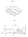
- FIG. 3 shows a segment of the plate fin 2 divided into four equal segments in the row and column directions from the tube holes 3
- FIG. 4 shows a sectional view of the same taken along line A-A in FIG. 2
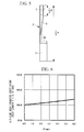
- FIG. 5 shows a sectional view of the same taken along line B-B in FIG. 2
- the tube hole 3 has a collar 3A formed by burring around the hole.
- the tube hole 3 is bored such that the diameter thereof, ⁇ , is slightly larger than the narrowed diameter of the heat transfer tube 4 (for example, 6.35 mm).
- the collar 3A has a height of, for example, 1.2 mm, and the height of the collar 3A defines the fin pitch, Pf, of the multilayered plate fins 2.
- the plate fin 2 has at least three row-direction peak portions 5 provided in the row direction (width direction) with respect to each row of the tube holes 3 (four row-direction peak portions 5 are provided in this embodiment, and FIG. 4 shows two of them).
- the height, h2 for example, 0.7 mm
- central peak portions 5B and 5C provided at the central portion in the row direction is greater than the height, h1 (for example, 0.4 mm), of two both-end peak portions 5A and 5D provided at both ends in the row direction.
- the length, p, in the width direction from the lowest position to the highest position of the both-end peak portions 5A and 5D is, for example, 1.4 mm
- the length, q, in the width direction from the lowest position to the highest position of the central peak portions 5B and 5C is, for example, 2.8 mm.
- the row-direction peak portions 5 have substantially the same gradients.
- the plate fin 2 has plane portions 5E and 5F having a length in the width direction of r at both widthwise ends. Note that the apex and base of the peak portions 5A to 5D are rounded with an arbitrary curvature.
- two column-direction peak portions 6 are provided in the column direction, between the adjacent tube holes 3 in the column direction.
- the column-direction peak portions 6 have the same height as the height, h1 (for example, 0.4 mm), of the both-end peak portions 5A and 5D provided in the row direction and have a flat portion (plane portion) 7 at the apex thereof.
- the length, F, of the flat portion 7 ( FIG. 5 shows 1/2 F) is set to be one-third or less of the column pitch n or 0.5 or less of the pitch, Pt, between tube sections of the heat transfer tube 4 (see FIG. 2 ), i.e., in the range of about 2 mm to 6 mm.
- the column-direction peak portions 6 having the flat portion 7 at the apex between the adjacent tube holes 3 in the column direction, three-dimensional peak portions projecting both of them in the row and column directions (three-dimensional directions) are formed between the adjacent tube holes 3 in the column direction.
- two central peak portions, 5B and 5C, arranged in the row direction are disposed between the adjacent tube holes 3 in the column direction, two column-direction peak portions 6 are provided corresponding thereto.
- one column-direction peak portion 6 is provided corresponding thereto.
- a blower fan (not shown) blows air to the fin-and-tube type heat exchanger 1, in the width direction of the plate fins 2.
- the air circulating between the multiple plate fins 2 exchanges heat with the refrigerant circulating in the heat transfer tube 4.
- the air flowing between the plate fins 2 is guided to the plane portion 5E, having a width r and provided at the front end in the width direction, and flows smoothly between the plate fins 2.
- the air While circulating between the plate fins 2, the air is guided by the row-direction peak portions 5 and the column-direction peak portions 6, repeats collision and separation at the peak surfaces, generates turbulence sufficient to destroy the thermal boundary layer, and is directed toward the immediate wake region of the heat transfer tube 4 mainly by the effect of the column-direction peak portions 6. Then, the air having flowed between the plate fins 2 is discharged from the rear end thereof.
- each row-direction peak portion 5 is provided in the row direction of the plate fin 2.
- the both-end peak portions 5A and 5D are low, and the central peak portions 5B and 5C are higher than the both-end peak portions 5A and 5D.
- the column-direction peak portions 6 corresponding to the central peak portions 5B and 5C are provided in the column direction, the effect of the peak portions 5 and 6 can make the average local heat-transfer coefficient at an air inlet a substantially constant high value.
- the heat-transfer coefficient is high at the collision surfaces and is low at the separation surfaces. Therefore, by increasing a region having a high heat-transfer coefficient in the collision surfaces, the average heat-transfer coefficient can be improved. Furthermore, the peak portions 5 can increase the heat transfer area, which also improves the heat transfer performance. If only an improvement of the fin-side heat-transfer coefficient is intended, the heights of all the row-direction peak portions 5 may be increased. However, this increases the fin-side circulation resistance (increases the air-side pressure loss) and increases the input to the blower fan, which is undesirable from the standpoint of energy saving.
- the average local heat-transfer coefficient can be made a high value without increasing the circulation resistance.
- the peak portion 5D at the rear end of the plate fin 2 is low, the heat-transfer coefficient at the airflow outlet behind the heat transfer tube 4 fitted to the tube holes 3 can be recovered. This may be because the low peak portion 5D at the rear end of the fin forms an airflow flowing in the wake region of the heat transfer tube 4, promoting heat exchange between the fins and the airflow. Furthermore, in the row-direction peak portions 5 of the plate fin 2, because the length, q, in the width direction, of the central peak portions 5B and 5C provided in the row direction is larger than (twice the length of) the length, p, in the width direction, of the both-end peak portions 5A and 5D, the gradients of all these peak portions 5A to 5D can be made substantially the same.
- frost tends to accumulate at the front edges of the plate fins 2 during heating, where the heat-transfer coefficient is high. If the front-end peak portion 5A of the plate fin 2 is high, the space between the fins is narrow. As a result, frost clogs the air flow path, or an increase in flow path resistance due to the frost decreases the quantity of air, accelerating a decrease in heat exchange capacity and making the frost more likely to accumulate.
- the plate fin 2 has column-direction peak portions 6 provided in the column direction, between the adjacent tube holes 3 in the column direction.
- the heat-transfer coefficient can also be improved by the turbulence promoting effect caused by the column-direction peak portions 6.
- the column-direction peak portions 6 can form downward slopes (inclined surfaces) leading to the tube holes 3, between the adjacent tube holes 3 in the column direction, the airflow circulating between the plate fins 2, along the slopes, can be made to flow behind the heat transfer tube 4 fitted to the tube holes 3. This can reduce the dead region (non-effective heat transfer region) behind the heat transfer tube 4 (the tube holes 3) of the plate fins 2 to increase the effective heat transfer area of the fins, which improves the heat-transfer coefficient corresponding thereto.
- each row-direction peak portion 5 is provided, and the column-direction peak portions 6 corresponding to two central peak portions 5B and 5C, which are large in height, are provided.
- This provides a structure in which three-dimensional peak portions projecting both in the row and column directions (three-dimensional directions) are provided between the adjacent tube holes 3 in the column direction, improving the balance of resistance against the airflow. Therefore, not only does the airflow flow in the central region between the adjacent heat transfer tube 4 in the column direction of the plate fin 2, but also sufficient airflow is formed around the heat transfer tube 4. Accordingly, it is possible to further increase the effective heat transfer area and further improve the heat-transfer coefficient in the immediate wake region of the heat transfer tube 4.
- the flat portion (plane portion) 7 is formed at the apex of the column-direction peak portion 6.
- the flat portion 7 can increase the size of the region having a high local air-side heat-transfer coefficient, which can improve the average heat-transfer coefficient.
- the length, F, of the flat portion 7 in the column direction is set to be one-third or less of the column pitch n, or 0.5 or less of the pitch, Pt, between tube sections of the heat transfer tube 4, i.e., in the range of about 2 mm to 6 mm.
- the air-side heat-transfer coefficient, ⁇ a can be further increased by several percent compared with a case where the flat length, F, is 0.
- the above-mentioned range is appropriate.
- the heat-transfer coefficient can be improved. Furthermore, by forming four row-direction peak portions 5, of which the peak portions 5A and 5D at both ends are low and the two central peak portions 5B and 5C formed therebetween are high, the size of the airflow collision surfaces, having a high heat-transfer coefficient, is increased. Because this can make the average local heat-transfer coefficient at the row-direction peak portions 5 a constant high value, the heat transfer performance can be improved to a constant high value.
- the peak portion 5D at the rear end of the row-direction peak portions 5 is made low so that the peak portion 5D forms an airflow flowing in the wake region of the heat transfer tube 4, it is possible to promote heat exchange between the fins and the airflow in that region.
- the heat-transfer coefficient in the wake region of the heat transfer tube 4 can be improved.
- the peak portion 5A at the front end of the row-direction peak portions 5 is made low so as to provide a large space between the fins at the front ends of the fins having a high heat-transfer coefficient, frosting on the fins can be suppressed.
- both-end peak portions 5A and 5D of the row-direction peak portions 5, which are low in height, have a small width
- the two central peak portions 5B and 5C formed therebetween, which are large in height have a large width such that their gradients are substantially the same.
- This makes it possible to increase the height of the row-direction peak portions 5 to make the average local heat-transfer coefficient at the row-direction peak portions 5 a constant high value, while suppressing an increase in the circulation resistance (airflow-side pressure loss) against the airflow and reducing the input to the blower fan.
- the plane portions 5E and 5F are provided at both widthwise ends of the plate fin 2 to guide the inflow of the air to reduce the inflow resistance (airflow-side pressure loss), it is possible to reduce the input to the blower fan and save energy.
- the provision of the downward inclined surfaces, leading to the tube holes 3, of the three-dimensional peak portions projecting both in the row and column directions and provided between the adjacent tube holes 3 in the column direction allows the airflow circulating between the plate fins 2 to flow toward the immediate wake of the heat transfer tube 4. Because this can reduce the dead region of the plate fins 2 and can increase the effective heat transfer area, the heat transfer performance can be improved corresponding thereto.
- two column-direction peak portions 6 corresponding to the two central peak portions 5B and 5C of the row-direction peak portions 5, which are large in height, are provided to form the peak portions projecting in the three-dimensional directions.
- the region having a high local air-side heat-transfer coefficient is increased. This can improve the average heat-transfer coefficient.
- the length, F, of the flat portion 7 in the column direction is set to be one-third or less of the column pitch n, or 0.4 or less of the pitch, Pt, between tube sections of the heat transfer tube 4, i.e., in the range of about 2 mm to 6 mm.
- the air-side heat-transfer coefficient, ⁇ a can be further increased by several percent compared with a case where the flat length, F, is 0, while suppressing the air-side circulation resistance (pressure loss).
- the heat transfer performance can be improved. Furthermore, an improvement of the heat-transfer coefficient and an enhancement of the heat transfer performance achieved by improving the structure of the fins make it possible to secure sufficient heat exchange capacity while increasing the fin pitch. This can reduce the number of plate fins 2 and can reduce the material cost accompanied by a reduction in diameter of the heat transfer tube 4 (for example, a tube diameter ⁇ of 6.35 mm). Accordingly, the costs can be reduced.
- the present invention is not limited to the invention according to the above-described embodiment, and it can be arbitrarily modified within a scope not departing from the spirit thereof.
- the dimensions of the parts of the plate fins are specified in the above-described embodiment, they are merely examples, and the present invention is not limited thereto.
- the numbers of rows and columns of the tube holes 3 can of course be arbitrarily modified corresponding to the capacity of the heat exchanger.
Landscapes
- Engineering & Computer Science (AREA)
- Physics & Mathematics (AREA)
- Thermal Sciences (AREA)
- Mechanical Engineering (AREA)
- General Engineering & Computer Science (AREA)
- Geometry (AREA)
- Heat-Exchange Devices With Radiators And Conduit Assemblies (AREA)
- Air Filters, Heat-Exchange Apparatuses, And Housings Of Air-Conditioning Units (AREA)
Applications Claiming Priority (2)
| Application Number | Priority Date | Filing Date | Title |
|---|---|---|---|
| JP2007340369A JP5185611B2 (ja) | 2007-12-28 | 2007-12-28 | フィンアンドチューブ型熱交換器 |
| PCT/JP2008/071466 WO2009084347A1 (fr) | 2007-12-28 | 2008-11-26 | Échangeur de chaleur du type à ailettes et tubes |
Publications (2)
| Publication Number | Publication Date |
|---|---|
| EP2224198A1 true EP2224198A1 (fr) | 2010-09-01 |
| EP2224198A4 EP2224198A4 (fr) | 2014-01-29 |
Family
ID=40824070
Family Applications (1)
| Application Number | Title | Priority Date | Filing Date |
|---|---|---|---|
| EP08866432.1A Withdrawn EP2224198A4 (fr) | 2007-12-28 | 2008-11-26 | Échangeur de chaleur du type à ailettes et tubes |
Country Status (3)
| Country | Link |
|---|---|
| EP (1) | EP2224198A4 (fr) |
| JP (1) | JP5185611B2 (fr) |
| WO (1) | WO2009084347A1 (fr) |
Cited By (1)
| Publication number | Priority date | Publication date | Assignee | Title |
|---|---|---|---|---|
| WO2019186071A1 (fr) * | 2018-03-27 | 2019-10-03 | Systemair Ac Sas | Echangeur haute performance anti-givre |
Families Citing this family (3)
| Publication number | Priority date | Publication date | Assignee | Title |
|---|---|---|---|---|
| JP5958771B2 (ja) * | 2011-10-11 | 2016-08-02 | パナソニックIpマネジメント株式会社 | フィンチューブ熱交換器 |
| CN114963845B (zh) * | 2022-07-04 | 2025-11-28 | 珠海格力电器股份有限公司 | 翅片、换热器及空调系统 |
| KR20240050865A (ko) | 2022-10-12 | 2024-04-19 | 엘지전자 주식회사 | 열교환기 |
Family Cites Families (15)
| Publication number | Priority date | Publication date | Assignee | Title |
|---|---|---|---|---|
| FR633229A (fr) * | 1927-04-23 | 1928-01-25 | Radiateur de chauffage ou réfrigération | |
| US2046791A (en) * | 1934-01-17 | 1936-07-07 | Przyborowski Stanislaus | Radiator |
| JPS6027916B2 (ja) * | 1978-04-24 | 1985-07-02 | ダイキン工業株式会社 | 熱交換器 |
| JPS57104185U (fr) * | 1980-12-15 | 1982-06-26 | ||
| JPS60216188A (ja) * | 1984-04-10 | 1985-10-29 | Matsushita Electric Ind Co Ltd | 熱交換器のフイン |
| JPH01181093A (ja) * | 1988-01-14 | 1989-07-19 | Nippon Denso Co Ltd | フィン付熱交換器 |
| JPH0626778A (ja) * | 1992-07-07 | 1994-02-04 | Fujitsu General Ltd | 熱交換器 |
| JPH08170889A (ja) * | 1994-12-16 | 1996-07-02 | Daikin Ind Ltd | クロスフィン熱交換器 |
| JP3358355B2 (ja) * | 1994-12-22 | 2002-12-16 | ダイキン工業株式会社 | クロスフィン熱交換器 |
| JP3367353B2 (ja) * | 1996-11-12 | 2003-01-14 | 松下電器産業株式会社 | フィン付き熱交換器 |
| JP2001174181A (ja) * | 1999-10-06 | 2001-06-29 | Mitsubishi Heavy Ind Ltd | フィンアンドチューブ熱交換器及びこれを備えた空気調和機 |
| JP2001317890A (ja) * | 2000-05-01 | 2001-11-16 | Matsushita Electric Ind Co Ltd | フィン付き熱交換器 |
| US7261147B2 (en) * | 2003-05-28 | 2007-08-28 | Lg Electronics Inc. | Heat exchanger |
| JP2006138504A (ja) * | 2004-11-10 | 2006-06-01 | Mitsubishi Heavy Ind Ltd | 熱交換器および空気調和機 |
| WO2007108386A1 (fr) * | 2006-03-23 | 2007-09-27 | Matsushita Electric Industrial Co., Ltd. | Echangeur de chaleur a tubes a ailettes, ailette d'echangeur de chaleur et dispositif de pompe a chaleur |
-
2007
- 2007-12-28 JP JP2007340369A patent/JP5185611B2/ja active Active
-
2008
- 2008-11-26 WO PCT/JP2008/071466 patent/WO2009084347A1/fr not_active Ceased
- 2008-11-26 EP EP08866432.1A patent/EP2224198A4/fr not_active Withdrawn
Cited By (2)
| Publication number | Priority date | Publication date | Assignee | Title |
|---|---|---|---|---|
| WO2019186071A1 (fr) * | 2018-03-27 | 2019-10-03 | Systemair Ac Sas | Echangeur haute performance anti-givre |
| FR3079604A1 (fr) * | 2018-03-27 | 2019-10-04 | Systemair Ac Sas | Echangeur haute performance anti-givre |
Also Published As
| Publication number | Publication date |
|---|---|
| WO2009084347A1 (fr) | 2009-07-09 |
| JP2009162406A (ja) | 2009-07-23 |
| JP5185611B2 (ja) | 2013-04-17 |
| EP2224198A4 (fr) | 2014-01-29 |
Similar Documents
| Publication | Publication Date | Title |
|---|---|---|
| EP2857785B1 (fr) | Echangeur de chaleur et climatiseur | |
| US7913750B2 (en) | Louvered air center with vortex generating extensions for compact heat exchanger | |
| EP2236972B1 (fr) | Ailette pour échangeur thermique et échangeur thermique utilisant l'ailette | |
| EP3018439B1 (fr) | Échangeur de chaleur de tube à ailette | |
| EP2447659A2 (fr) | Échangeur de chaleur et ailette correspondante | |
| US10422588B2 (en) | Heat exchanger coil with offset fins | |
| US4715437A (en) | Heat exchanger | |
| KR101224071B1 (ko) | 튜브형 열교환기 | |
| CN101592421A (zh) | 翅片管型热交换器 | |
| US20070240865A1 (en) | High performance louvered fin for heat exchanger | |
| JPH0791873A (ja) | フィンアンドチューブ形熱交換器 | |
| JP4952196B2 (ja) | 熱交換器 | |
| US20090173479A1 (en) | Louvered air center for compact heat exchanger | |
| EP3608618B1 (fr) | Échangeur thermique et dispositif à cycle de réfrigération | |
| EP2447660A2 (fr) | Échangeur de chaleur et son tuyau à microcanaux | |
| EP2224198A1 (fr) | Échangeur de chaleur du type à ailettes et tubes | |
| US6786276B2 (en) | Heat exchanger tube with optimized plates | |
| JP2004263881A (ja) | 伝熱フィン、熱交換器、カーエアコン用エバポレータ及びコンデンサ | |
| WO2018040037A1 (fr) | Échangeur de chaleur à micro-canal et réfrigérateur refroidi par air | |
| JP2013092306A (ja) | フィンチューブ熱交換器 | |
| US12078431B2 (en) | Microchannel heat exchanger for a furnace | |
| JP5138408B2 (ja) | フィン・アンド・チューブ式熱交換器 | |
| JP4497394B2 (ja) | 熱交換器及び空気調和機 | |
| JPWO2005073655A1 (ja) | 熱交換器及びこれを含む空調装置 | |
| JP5084304B2 (ja) | フィンチューブ型熱交換器及び冷凍サイクル |
Legal Events
| Date | Code | Title | Description |
|---|---|---|---|
| PUAI | Public reference made under article 153(3) epc to a published international application that has entered the european phase |
Free format text: ORIGINAL CODE: 0009012 |
|
| 17P | Request for examination filed |
Effective date: 20100430 |
|
| AK | Designated contracting states |
Kind code of ref document: A1 Designated state(s): AT BE BG CH CY CZ DE DK EE ES FI FR GB GR HR HU IE IS IT LI LT LU LV MC MT NL NO PL PT RO SE SI SK TR |
|
| AX | Request for extension of the european patent |
Extension state: AL BA MK RS |
|
| DAX | Request for extension of the european patent (deleted) | ||
| A4 | Supplementary search report drawn up and despatched |
Effective date: 20140108 |
|
| RIC1 | Information provided on ipc code assigned before grant |
Ipc: F28F 1/32 20060101AFI20131220BHEP |
|
| STAA | Information on the status of an ep patent application or granted ep patent |
Free format text: STATUS: THE APPLICATION IS DEEMED TO BE WITHDRAWN |
|
| 18D | Application deemed to be withdrawn |
Effective date: 20140805 |