WO2009084347A1 - Échangeur de chaleur du type à ailettes et tubes - Google Patents
Échangeur de chaleur du type à ailettes et tubes Download PDFInfo
- Publication number
- WO2009084347A1 WO2009084347A1 PCT/JP2008/071466 JP2008071466W WO2009084347A1 WO 2009084347 A1 WO2009084347 A1 WO 2009084347A1 JP 2008071466 W JP2008071466 W JP 2008071466W WO 2009084347 A1 WO2009084347 A1 WO 2009084347A1
- Authority
- WO
- WIPO (PCT)
- Prior art keywords
- fin
- heat transfer
- tube
- heat exchanger
- row
- Prior art date
- Legal status (The legal status is an assumption and is not a legal conclusion. Google has not performed a legal analysis and makes no representation as to the accuracy of the status listed.)
- Ceased
Links
Images

Classifications
-
- F—MECHANICAL ENGINEERING; LIGHTING; HEATING; WEAPONS; BLASTING
- F28—HEAT EXCHANGE IN GENERAL
- F28D—HEAT-EXCHANGE APPARATUS, NOT PROVIDED FOR IN ANOTHER SUBCLASS, IN WHICH THE HEAT-EXCHANGE MEDIA DO NOT COME INTO DIRECT CONTACT
- F28D1/00—Heat-exchange apparatus having stationary conduit assemblies for one heat-exchange medium only, the media being in contact with different sides of the conduit wall, in which the other heat-exchange medium is a large body of fluid, e.g. domestic or motor car radiators
- F28D1/02—Heat-exchange apparatus having stationary conduit assemblies for one heat-exchange medium only, the media being in contact with different sides of the conduit wall, in which the other heat-exchange medium is a large body of fluid, e.g. domestic or motor car radiators with heat-exchange conduits immersed in the body of fluid
- F28D1/04—Heat-exchange apparatus having stationary conduit assemblies for one heat-exchange medium only, the media being in contact with different sides of the conduit wall, in which the other heat-exchange medium is a large body of fluid, e.g. domestic or motor car radiators with heat-exchange conduits immersed in the body of fluid with tubular conduits
- F28D1/047—Heat-exchange apparatus having stationary conduit assemblies for one heat-exchange medium only, the media being in contact with different sides of the conduit wall, in which the other heat-exchange medium is a large body of fluid, e.g. domestic or motor car radiators with heat-exchange conduits immersed in the body of fluid with tubular conduits the conduits being bent, e.g. in a serpentine or zig-zag
- F28D1/0477—Heat-exchange apparatus having stationary conduit assemblies for one heat-exchange medium only, the media being in contact with different sides of the conduit wall, in which the other heat-exchange medium is a large body of fluid, e.g. domestic or motor car radiators with heat-exchange conduits immersed in the body of fluid with tubular conduits the conduits being bent, e.g. in a serpentine or zig-zag the conduits being bent in a serpentine or zig-zag
-
- F—MECHANICAL ENGINEERING; LIGHTING; HEATING; WEAPONS; BLASTING
- F28—HEAT EXCHANGE IN GENERAL
- F28F—DETAILS OF HEAT-EXCHANGE AND HEAT-TRANSFER APPARATUS, OF GENERAL APPLICATION
- F28F1/00—Tubular elements; Assemblies of tubular elements
- F28F1/10—Tubular elements and assemblies thereof with means for increasing heat-transfer area, e.g. with fins, with projections, with recesses
- F28F1/12—Tubular elements and assemblies thereof with means for increasing heat-transfer area, e.g. with fins, with projections, with recesses the means being only outside the tubular element
- F28F1/24—Tubular elements and assemblies thereof with means for increasing heat-transfer area, e.g. with fins, with projections, with recesses the means being only outside the tubular element and extending transversely
- F28F1/32—Tubular elements and assemblies thereof with means for increasing heat-transfer area, e.g. with fins, with projections, with recesses the means being only outside the tubular element and extending transversely the means having portions engaging further tubular elements
Definitions
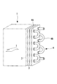
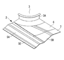
- FIG. 3 is a perspective view of a piece that is divided into four equal parts in a row direction and a step direction around a tube hole of a plate fin shown in FIG.
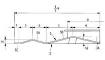
- FIG. 4 is a cross-sectional view corresponding to the AA cross section of FIG. 2 of one piece of the plate fin shown in FIG. 3.
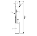
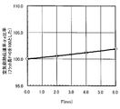
- FIG. 4 is a cross-sectional view corresponding to the BB cross section of FIG. 2 of one piece of the plate fin shown in FIG. 3. It is a relationship graph of the flat part length F of the step direction peak part of the plate fin shown in FIG. 2, and the air side heat transfer coefficient (alpha) ratio.
- the heat transfer coefficient at the collision surface is high and the heat transfer coefficient at the separation surface is low.
- the heat transfer coefficient at the separation surface is low.
- the heat transfer coefficient can be improved as an average value.
- the heat transfer area can be increased by the mountain portion 5, the heat transfer performance can be improved also by this. If only the heat transfer coefficient improvement on the fin side is considered, all the heights of the ridges 5 in the row direction need only be increased. Since the input to is increased, it is not preferable for energy saving.
Landscapes
- Engineering & Computer Science (AREA)
- Physics & Mathematics (AREA)
- Thermal Sciences (AREA)
- Mechanical Engineering (AREA)
- General Engineering & Computer Science (AREA)
- Geometry (AREA)
- Heat-Exchange Devices With Radiators And Conduit Assemblies (AREA)
- Air Filters, Heat-Exchange Apparatuses, And Housings Of Air-Conditioning Units (AREA)
Abstract
L'invention concerne un échangeur de chaleur du type à ailettes et tubes ayant un rendement plus élevé réalisé par l'amélioration du coefficient de transmission de chaleur des ailettes sans augmentation de la résistance à l'écoulement de l'air (perte de pression). L'échangeur de chaleur du type à ailettes et tubes (1) a un grand nombre d'ailettes-plaques (2) arrangées de manière parallèle selon un pas prédéterminé et permettant à l'air de s'écouler entre les ailettes-plaques, et a également des tubes de transfert de chaleur (4) insérés en contact étroit dans des trous de tubes (3) mis en œuvre sur les ailettes-plaques (2) selon un pas entre-rangs prédéterminé et selon un pas entre-colonnes prédéterminé et permettant au fluide de s'écouler dans les tubes de transfert de chaleur. Une ailette-plaque (2) a une section conique (6) se trouvant entre les trous de tubes (3) de manière adjacente dans la direction des colonnes et s'étendant dans la direction des colonnes. Sur la partie supérieure de la section conique (6) se trouve une section plate (7).
Priority Applications (1)
| Application Number | Priority Date | Filing Date | Title |
|---|---|---|---|
| EP08866432.1A EP2224198A4 (fr) | 2007-12-28 | 2008-11-26 | Échangeur de chaleur du type à ailettes et tubes |
Applications Claiming Priority (2)
| Application Number | Priority Date | Filing Date | Title |
|---|---|---|---|
| JP2007-340369 | 2007-12-28 | ||
| JP2007340369A JP5185611B2 (ja) | 2007-12-28 | 2007-12-28 | フィンアンドチューブ型熱交換器 |
Publications (1)
| Publication Number | Publication Date |
|---|---|
| WO2009084347A1 true WO2009084347A1 (fr) | 2009-07-09 |
Family
ID=40824070
Family Applications (1)
| Application Number | Title | Priority Date | Filing Date |
|---|---|---|---|
| PCT/JP2008/071466 Ceased WO2009084347A1 (fr) | 2007-12-28 | 2008-11-26 | Échangeur de chaleur du type à ailettes et tubes |
Country Status (3)
| Country | Link |
|---|---|
| EP (1) | EP2224198A4 (fr) |
| JP (1) | JP5185611B2 (fr) |
| WO (1) | WO2009084347A1 (fr) |
Cited By (1)
| Publication number | Priority date | Publication date | Assignee | Title |
|---|---|---|---|---|
| CN114963845A (zh) * | 2022-07-04 | 2022-08-30 | 珠海格力电器股份有限公司 | 翅片、换热器及空调系统 |
Families Citing this family (3)
| Publication number | Priority date | Publication date | Assignee | Title |
|---|---|---|---|---|
| JP5958771B2 (ja) * | 2011-10-11 | 2016-08-02 | パナソニックIpマネジメント株式会社 | フィンチューブ熱交換器 |
| FR3079604B1 (fr) * | 2018-03-27 | 2020-06-26 | Systemair Ac Sas | Echangeur haute performance anti-givre |
| KR20240050865A (ko) | 2022-10-12 | 2024-04-19 | 엘지전자 주식회사 | 열교환기 |
Citations (11)
| Publication number | Priority date | Publication date | Assignee | Title |
|---|---|---|---|---|
| JPS54140253A (en) * | 1978-04-24 | 1979-10-31 | Daikin Ind Ltd | Heat exchanger |
| JPS57104185U (fr) * | 1980-12-15 | 1982-06-26 | ||
| JPH01181093A (ja) * | 1988-01-14 | 1989-07-19 | Nippon Denso Co Ltd | フィン付熱交換器 |
| JPH0626778A (ja) * | 1992-07-07 | 1994-02-04 | Fujitsu General Ltd | 熱交換器 |
| JPH08170889A (ja) * | 1994-12-16 | 1996-07-02 | Daikin Ind Ltd | クロスフィン熱交換器 |
| JPH08178573A (ja) | 1994-12-22 | 1996-07-12 | Daikin Ind Ltd | クロスフィン熱交換器 |
| JPH10141880A (ja) | 1996-11-12 | 1998-05-29 | Matsushita Electric Ind Co Ltd | フィン付き熱交換器 |
| JP2001174181A (ja) * | 1999-10-06 | 2001-06-29 | Mitsubishi Heavy Ind Ltd | フィンアンドチューブ熱交換器及びこれを備えた空気調和機 |
| JP2001317890A (ja) * | 2000-05-01 | 2001-11-16 | Matsushita Electric Ind Co Ltd | フィン付き熱交換器 |
| JP2006138504A (ja) * | 2004-11-10 | 2006-06-01 | Mitsubishi Heavy Ind Ltd | 熱交換器および空気調和機 |
| WO2007108386A1 (fr) * | 2006-03-23 | 2007-09-27 | Matsushita Electric Industrial Co., Ltd. | Echangeur de chaleur a tubes a ailettes, ailette d'echangeur de chaleur et dispositif de pompe a chaleur |
Family Cites Families (4)
| Publication number | Priority date | Publication date | Assignee | Title |
|---|---|---|---|---|
| FR633229A (fr) * | 1927-04-23 | 1928-01-25 | Radiateur de chauffage ou réfrigération | |
| US2046791A (en) * | 1934-01-17 | 1936-07-07 | Przyborowski Stanislaus | Radiator |
| JPS60216188A (ja) * | 1984-04-10 | 1985-10-29 | Matsushita Electric Ind Co Ltd | 熱交換器のフイン |
| US7261147B2 (en) * | 2003-05-28 | 2007-08-28 | Lg Electronics Inc. | Heat exchanger |
-
2007
- 2007-12-28 JP JP2007340369A patent/JP5185611B2/ja active Active
-
2008
- 2008-11-26 WO PCT/JP2008/071466 patent/WO2009084347A1/fr not_active Ceased
- 2008-11-26 EP EP08866432.1A patent/EP2224198A4/fr not_active Withdrawn
Patent Citations (11)
| Publication number | Priority date | Publication date | Assignee | Title |
|---|---|---|---|---|
| JPS54140253A (en) * | 1978-04-24 | 1979-10-31 | Daikin Ind Ltd | Heat exchanger |
| JPS57104185U (fr) * | 1980-12-15 | 1982-06-26 | ||
| JPH01181093A (ja) * | 1988-01-14 | 1989-07-19 | Nippon Denso Co Ltd | フィン付熱交換器 |
| JPH0626778A (ja) * | 1992-07-07 | 1994-02-04 | Fujitsu General Ltd | 熱交換器 |
| JPH08170889A (ja) * | 1994-12-16 | 1996-07-02 | Daikin Ind Ltd | クロスフィン熱交換器 |
| JPH08178573A (ja) | 1994-12-22 | 1996-07-12 | Daikin Ind Ltd | クロスフィン熱交換器 |
| JPH10141880A (ja) | 1996-11-12 | 1998-05-29 | Matsushita Electric Ind Co Ltd | フィン付き熱交換器 |
| JP2001174181A (ja) * | 1999-10-06 | 2001-06-29 | Mitsubishi Heavy Ind Ltd | フィンアンドチューブ熱交換器及びこれを備えた空気調和機 |
| JP2001317890A (ja) * | 2000-05-01 | 2001-11-16 | Matsushita Electric Ind Co Ltd | フィン付き熱交換器 |
| JP2006138504A (ja) * | 2004-11-10 | 2006-06-01 | Mitsubishi Heavy Ind Ltd | 熱交換器および空気調和機 |
| WO2007108386A1 (fr) * | 2006-03-23 | 2007-09-27 | Matsushita Electric Industrial Co., Ltd. | Echangeur de chaleur a tubes a ailettes, ailette d'echangeur de chaleur et dispositif de pompe a chaleur |
Non-Patent Citations (1)
| Title |
|---|
| See also references of EP2224198A4 * |
Cited By (1)
| Publication number | Priority date | Publication date | Assignee | Title |
|---|---|---|---|---|
| CN114963845A (zh) * | 2022-07-04 | 2022-08-30 | 珠海格力电器股份有限公司 | 翅片、换热器及空调系统 |
Also Published As
| Publication number | Publication date |
|---|---|
| JP2009162406A (ja) | 2009-07-23 |
| EP2224198A1 (fr) | 2010-09-01 |
| JP5185611B2 (ja) | 2013-04-17 |
| EP2224198A4 (fr) | 2014-01-29 |
Similar Documents
| Publication | Publication Date | Title |
|---|---|---|
| EP2236972B1 (fr) | Ailette pour échangeur thermique et échangeur thermique utilisant l'ailette | |
| CN103477177B (zh) | 热交换器 | |
| US10422588B2 (en) | Heat exchanger coil with offset fins | |
| EP3021064B1 (fr) | Dispositif de pompe à chaleur | |
| JP4952196B2 (ja) | 熱交換器 | |
| JP7136778B2 (ja) | 低レイノルズ数気流のためのフィン改善策 | |
| JP2015004451A (ja) | フィンチューブ熱交換器 | |
| JP5185611B2 (ja) | フィンアンドチューブ型熱交換器 | |
| EP3608618B1 (fr) | Échangeur thermique et dispositif à cycle de réfrigération | |
| JP2008215670A (ja) | 伝熱フィン、フィンチューブ型熱交換器および冷凍サイクル装置 | |
| JP2013092306A (ja) | フィンチューブ熱交換器 | |
| JP2004263881A (ja) | 伝熱フィン、熱交換器、カーエアコン用エバポレータ及びコンデンサ | |
| JP5138408B2 (ja) | フィン・アンド・チューブ式熱交換器 | |
| JP6706839B2 (ja) | フィンチューブ熱交換器 | |
| JP5039366B2 (ja) | フィンアンドチューブ型熱交換器 | |
| JP5084304B2 (ja) | フィンチューブ型熱交換器及び冷凍サイクル | |
| JP2019015432A (ja) | 熱交換器及び熱交換ユニット | |
| JPWO2021234957A5 (fr) | ||
| JP2009162433A (ja) | 伝熱部材 | |
| KR101601085B1 (ko) | 증발기 | |
| JP4876660B2 (ja) | フィン付き熱交換器及び空気調和機 | |
| CN212457513U (zh) | 换热器、空调器 | |
| JP2006097953A (ja) | フィン付き熱交換器 | |
| JP2008121950A (ja) | フィン付き熱交換器 | |
| KR20110078520A (ko) | 분리된 열에 서로 다른 휜의 개수와 다른 휜의 형상을 갖는 휜-관 열교환기 |
Legal Events
| Date | Code | Title | Description |
|---|---|---|---|
| 121 | Ep: the epo has been informed by wipo that ep was designated in this application |
Ref document number: 08866432 Country of ref document: EP Kind code of ref document: A1 |
|
| WWE | Wipo information: entry into national phase |
Ref document number: 2008866432 Country of ref document: EP |
|
| NENP | Non-entry into the national phase |
Ref country code: DE |