EP2224236A1 - Vorrichtung zum Messen der Wechselstrommagnetisierung von Materialien und Verfahren zur Erkennung von Biomolekülen - Google Patents
Vorrichtung zum Messen der Wechselstrommagnetisierung von Materialien und Verfahren zur Erkennung von Biomolekülen Download PDFInfo
- Publication number
- EP2224236A1 EP2224236A1 EP10154646A EP10154646A EP2224236A1 EP 2224236 A1 EP2224236 A1 EP 2224236A1 EP 10154646 A EP10154646 A EP 10154646A EP 10154646 A EP10154646 A EP 10154646A EP 2224236 A1 EP2224236 A1 EP 2224236A1
- Authority
- EP
- European Patent Office
- Prior art keywords
- frequency
- magnetization
- bio
- sample
- magnetic
- Prior art date
- Legal status (The legal status is an assumption and is not a legal conclusion. Google has not performed a legal analysis and makes no representation as to the accuracy of the status listed.)
- Granted
Links
Images


Classifications
-
- G—PHYSICS
- G01—MEASURING; TESTING
- G01N—INVESTIGATING OR ANALYSING MATERIALS BY DETERMINING THEIR CHEMICAL OR PHYSICAL PROPERTIES
- G01N27/00—Investigating or analysing materials by the use of electric, electrochemical, or magnetic means
- G01N27/72—Investigating or analysing materials by the use of electric, electrochemical, or magnetic means by investigating magnetic variables
- G01N27/74—Investigating or analysing materials by the use of electric, electrochemical, or magnetic means by investigating magnetic variables of fluids
- G01N27/745—Investigating or analysing materials by the use of electric, electrochemical, or magnetic means by investigating magnetic variables of fluids for detecting magnetic beads used in biochemical assays
-
- B—PERFORMING OPERATIONS; TRANSPORTING
- B82—NANOTECHNOLOGY
- B82Y—SPECIFIC USES OR APPLICATIONS OF NANOSTRUCTURES; MEASUREMENT OR ANALYSIS OF NANOSTRUCTURES; MANUFACTURE OR TREATMENT OF NANOSTRUCTURES
- B82Y15/00—Nanotechnology for interacting, sensing or actuating, e.g. quantum dots as markers in protein assays or molecular motors
-
- B—PERFORMING OPERATIONS; TRANSPORTING
- B82—NANOTECHNOLOGY
- B82Y—SPECIFIC USES OR APPLICATIONS OF NANOSTRUCTURES; MEASUREMENT OR ANALYSIS OF NANOSTRUCTURES; MANUFACTURE OR TREATMENT OF NANOSTRUCTURES
- B82Y25/00—Nanomagnetism, e.g. magnetoimpedance, anisotropic magnetoresistance, giant magnetoresistance or tunneling magnetoresistance
-
- B—PERFORMING OPERATIONS; TRANSPORTING
- B82—NANOTECHNOLOGY
- B82Y—SPECIFIC USES OR APPLICATIONS OF NANOSTRUCTURES; MEASUREMENT OR ANALYSIS OF NANOSTRUCTURES; MANUFACTURE OR TREATMENT OF NANOSTRUCTURES
- B82Y5/00—Nanobiotechnology or nanomedicine, e.g. protein engineering or drug delivery
-
- G—PHYSICS
- G01—MEASURING; TESTING
- G01N—INVESTIGATING OR ANALYSING MATERIALS BY DETERMINING THEIR CHEMICAL OR PHYSICAL PROPERTIES
- G01N33/00—Investigating or analysing materials by specific methods not covered by groups G01N1/00 - G01N31/00
- G01N33/48—Biological material, e.g. blood, urine; Haemocytometers
- G01N33/50—Chemical analysis of biological material, e.g. blood, urine; Testing involving biospecific ligand binding methods; Immunological testing
- G01N33/53—Immunoassay; Biospecific binding assay; Materials therefor
- G01N33/5302—Apparatus specially adapted for immunological test procedures
-
- G—PHYSICS
- G01—MEASURING; TESTING
- G01N—INVESTIGATING OR ANALYSING MATERIALS BY DETERMINING THEIR CHEMICAL OR PHYSICAL PROPERTIES
- G01N33/00—Investigating or analysing materials by specific methods not covered by groups G01N1/00 - G01N31/00
- G01N33/48—Biological material, e.g. blood, urine; Haemocytometers
- G01N33/50—Chemical analysis of biological material, e.g. blood, urine; Testing involving biospecific ligand binding methods; Immunological testing
- G01N33/53—Immunoassay; Biospecific binding assay; Materials therefor
- G01N33/543—Immunoassay; Biospecific binding assay; Materials therefor with an insoluble carrier for immobilising immunochemicals
- G01N33/54313—Immunoassay; Biospecific binding assay; Materials therefor with an insoluble carrier for immobilising immunochemicals the carrier being characterised by its particulate form
- G01N33/54326—Magnetic particles
- G01N33/54333—Modification of conditions of immunological binding reaction, e.g. use of more than one type of particle, use of chemical agents to improve binding, choice of incubation time or application of magnetic field during binding reaction
-
- G—PHYSICS
- G01—MEASURING; TESTING
- G01N—INVESTIGATING OR ANALYSING MATERIALS BY DETERMINING THEIR CHEMICAL OR PHYSICAL PROPERTIES
- G01N33/00—Investigating or analysing materials by specific methods not covered by groups G01N1/00 - G01N31/00
- G01N33/48—Biological material, e.g. blood, urine; Haemocytometers
- G01N33/50—Chemical analysis of biological material, e.g. blood, urine; Testing involving biospecific ligand binding methods; Immunological testing
- G01N33/53—Immunoassay; Biospecific binding assay; Materials therefor
- G01N33/543—Immunoassay; Biospecific binding assay; Materials therefor with an insoluble carrier for immobilising immunochemicals
- G01N33/54313—Immunoassay; Biospecific binding assay; Materials therefor with an insoluble carrier for immobilising immunochemicals the carrier being characterised by its particulate form
- G01N33/54346—Nanoparticles
-
- G—PHYSICS
- G01—MEASURING; TESTING
- G01N—INVESTIGATING OR ANALYSING MATERIALS BY DETERMINING THEIR CHEMICAL OR PHYSICAL PROPERTIES
- G01N33/00—Investigating or analysing materials by specific methods not covered by groups G01N1/00 - G01N31/00
- G01N33/48—Biological material, e.g. blood, urine; Haemocytometers
- G01N33/50—Chemical analysis of biological material, e.g. blood, urine; Testing involving biospecific ligand binding methods; Immunological testing
- G01N33/53—Immunoassay; Biospecific binding assay; Materials therefor
- G01N33/543—Immunoassay; Biospecific binding assay; Materials therefor with an insoluble carrier for immobilising immunochemicals
- G01N33/54366—Apparatus specially adapted for solid-phase testing
- G01N33/54373—Apparatus specially adapted for solid-phase testing involving physiochemical end-point determination, e.g. wave-guides, FETS, gratings
- G01N33/5438—Electrodes
Definitions
- the present invention is related to measuring magnetization of magnetic fluid. More particularly, the present invention relates to device for measuring ac magnetization of materials and method for detecting bio-molecules.
- Magnetic fluid is a colloid solution having magnetic nanoparticles dispersed in solvent.
- the material of magnetic nanoparticles is usually ferromagnetic.
- each magnetic nanoparticle owns permanent magnetic moment.
- magnetic nanoparticles are coated with surfactant.
- surfactant For example, hydrophilic organic material is used for surfactant to disperse magnetic nanoparticles into aqueous solution.
- surfactant and nano-scale size magnetic nanoparticles can be dispersed individually in solvent. Due to thermal energy, individual magnetic nanoparticles experience Brownian motion.
- each magnetic nanoparticle is ferromagnetic, i.e.
- the fifth order of O 5 on the right-hand side in Eq. (4) denotes the term of power 5 of ⁇ o mH/k B T. If the applied magnetic field is generated by alternative-current (ac) and shows a frequency f o , it can be found that the M exhibits non-zero components at frequencies of ⁇ f o , where ⁇ is positive odd integers. Consequently, magnetic fluid shows magnetization having frequencies of not only f o but also ⁇ f o under a weak ac magnetic field with frequency f o .
- M o is proportional to the total numbers N of individual magnetic nanoparticles showing response to the applied ac magnetic field.
- the amplitude of ⁇ f o -component of the magnetization M spectrum decreases when the total numbers N of individual magnetic nanoparticles is reduced.
- the reduction in the total numbers N of individual magnetic nanoparticles showing a response to the applied ac magnetic field can be achieved by making magnetic nanoparticles clustered or larger through certain reactions in liquid.
- the certain reactions can be the association between bio-probes and bio-targets in liquid.
- bio-probes are coated onto individual magnetic nanoparticles via the binding to the surfactant.
- magnetic nanoparticles become bio-functional and are able to bind with conjugated bio-targets.
- the antibody acts as bio-probes and is coated onto individual magnetic nanoparticles in liquid.
- bio-functionalized magnetic nanoparticles can bind with conjugated antigens. Due to the association between antigens and antibodies on individual magnetic nanoparticles, magnetic nanoparticles become clustered or larger. Hence, the total number N of individual magnetic nanoparticles in response to an applied ac magnetic field at certain fixed frequency is definitely reduced. So, it can be deduced that the amplitude of ⁇ f o -component of the magnetization M of bio-functionalized magnetic fluid decreases when magnetic nanoparticles bind with bio-targets. Furthermore, the decreasing in the amplitude is enhanced when more individual magnetic nanoparticles bind with bio-targets.
- the amount of bio-targets can be determined by measuring the reduction in the ⁇ f o -component of the magnetization M of bio-functionalized magnetic fluid. This is the fundamental mechanism for such bio-assay technology as immunomagnetic reduction (IMR).
- IMR immunomagnetic reduction
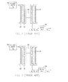
- FIG. 1 schematically shows the conventional architecture to measure the magnetization of magnetic fluid under an ac magnetic field.
- An excitation solenoid 102 is driven by an ac current generator 100 at frequency f o , so as to generate the ac magnetic field.
- a pick-up solenoid 104 is co-axially located inside the excitation solenoid 102.
- the pick-up solenoid 104 is referred as to magnetometer type.
- the magnetic fluid 108 is disposed inside the pick-up solenoid 104.
- the coil 106 is formed by the solenoids 102 and 104.
- ac voltages of frequencies ⁇ f o are output from the pick-up solenoid 104 of coil 106 to an electronic circuit 110.
- the electronic circuit 110 processes the voltage signals, with respect to various frequency components, to obtain the quantity at the component with the target frequency ⁇ T f o .
- the measurement architecture shown in FIG. 1 has disadvantages. Firstly, in addition to the magnetizations generated by magnetic fluid, the ambient signals can be detected by the pick-up solenoid. Secondly, the ac magnetic field (at f o ) generated with the excitation solenoid 102 is also probed. Thus, the induced voltage of f o at the output of the pick-up solenoid 104 is much stronger than those at other frequencies.
- the electronic circuit 110 it usually has amplifying units to amplify the voltage signal at ⁇ T f o for achieving high detection sensitivity.
- the amplifying units are operation amplifiers, having high-level limitation for the input voltages. The operation amplifiers can not properly work when input voltage is too high.
- the input voltage at f o is also amplified.
- the high-level limitation of operation amplifiers there is a limitation to amplify the voltage signal at ⁇ T f o in order to keep the total input voltages below the high-level limitation of operation amplifiers.
- FIG. 2 schematically shows the conventional architecture to measure the magnetization of magnetic fluid under an ac magnetic field.
- the pick-up solenoid 120 includes two sections: upper section and lower section. The coils in these two sections are wired in opposite direction and connected in series. The magnetic fluid 108 is disposed at one of the two sections, such as the upper section. Thus, ambient signals can be simultaneously sensed by these two sections. Voltages can be induced from out-leads of these two sections, and are cancelled with each other.
- the induced voltage at f o by the ac magnetic field at f o generated by the excitation solenoid 102 are cancelled for the gradiometer-type pick-up solenoid 120.
- the input voltage at f o to the electronic circuit can be greatly reduced for the measurement architecture in FIG. 2 as compared to that in FIG. 1 . This means that the amplification in the electronic circuit can be significantly increased when using gradiometer-type pick-up solenoid.
- the existence of input voltage of f o also generates the sub-harmonic signals to the output as mentioned before.
- the signals from the sample at the target frequency ⁇ T f o usually have unwanted components.
- the conventional designs can measure the ac magnetization of magnetic fluid.
- the target frequency is limited to ⁇ T f o , multiple of base frequency f o , resulting in unreliable output voltage at ⁇ T f o and their applications are limited.
- the invention provides a method to quantitatively measure an amount of bio-molecules in a sample.
- the method includes providing a solution having magnetic nanoparticles; coating bioprobe molecules to surfaces of the magnetic nanoparticles in the solution; measuring a first alternating current (ac) magnetization of the solution at a mixture frequency ( ⁇ f 1 + ⁇ f 2 ), wherein ⁇ or ⁇ is independently an integer larger than zero; adding a sample containing the bio-molecules to be detected to the solution, so that the biomolecules in the sample conjugate with the bioprobe molecules coated on the nanoparticles; and measuring a second ac magnetization of the solution at the mixture frequency ( ⁇ f 1 + ⁇ f 2 ) after adding the sample and incubation, so as to obtain an ac magnetization reduction at the mixture frequency ( ⁇ f 1 + ⁇ f 2 ) between the first and the second magnetization to determine the amount of the bio-molecules.
- ac alternating current
- the present invention also provides an apparatus to measure ac magnetization at mixture frequency.
- the apparatus includes an ac generating unit to generate at least a first ac current with a frequency f 1 and a second ac current with a frequency f 2 .
- a co-axial solenoid unit is driven by the first ac current and the second ac current to generate a first magnetic field and a second magnetic field.
- a gradiometer-type pick-up solenoid is disposed within the co-axial solenoid unit, wherein a sample is disposed in the pick-up solenoid for detection an ac magnetization of the sample. Multiple frequency-component signals corresponding to various frequency combinations of f 1 and f 2 are output.
- a signal processing circuit receives the signals containing various frequency components, wherein the signal processing circuit processes the signals and obtains the ac magnetization of the sample at a target frequency of ( ⁇ T f 1 + ⁇ T f 2 ).
- ⁇ T and ⁇ T are positive integers and the frequency f 1 and the frequency f 2 are two different frequencies generated by the first and the second ac currents, respectively.
- the present invention also provides a method to establish a relationship between an ac magnetization reduction and a bio-molecular concentration, wherein the ac magnetization reduction is a difference of ac magnetic susceptibilities in measured sample before and after the bio-molecules with known concentration are added into the measured sample.
- the method includes preparing a plurality of samples, wherein each of the samples include a solution having magnetic nanoparticles with coated bioprobe molecules thereon and bio-molecules with known concentration in the solution, wherein each sample has a different bio-molecular concentration. An ac magnetization reduction for each of the samples is measured.
- IMR % A - B 1 + ⁇ ⁇ o ⁇ + B
- IMR is the ac magnetization reduction in percentage
- ⁇ is the bio-molecular concentration in each sample
- A, B, ⁇ o , and ⁇ are fitting parameters to be fitted out to obtain a fitted curve.
- An ac magnetization reduction (IMR) for a to-be-measured sample is measured and a target bio-molecular concentration is obtained by using the fitted curve of the Eq. (5).
- the present invention provides a method to observe reaction between magnetic nanoparticles and bio-molecule in a sample.
- the method comprises providing a solution having magnetic nanoparticles; coating bioprobe molecules to surfaces of the magnetic nanoparticles in the solution; adding a sample containing the bio-molecules to be detected to the solution for an incubation time; and measuring an alternating current (ac) magnetization of the solution at a mixture frequency ( ⁇ f 1 + ⁇ f 2 ) as function of time, wherein ⁇ and ⁇ are independently integers larger than zero, f 1 and f 2 are two different frequencies.
- the ac magnetization is stable in an initial state and a reaction-completion state, but has a difference between the initial state and the reaction-completion state.
- FIG. 1 schematically shows the conventional architecture to measure the magnetization of magnetic fluid under an ac magnetic field.
- FIG. 2 schematically shows the conventional architecture to measure the magnetization of magnetic fluid under an ac magnetic field.
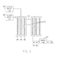
- FIG. 3 schematically shows an architecture to measure the magnetization of magnetic fluid under an ac magnetic field, according to an embodiment of the present invention.
- FIG. 4 schematically shows a circuit block diagram for measuring the magnetization of magnetic fluid, according to an embodiment of the present invention.
- FIG. 5 schematically shows a relationship between magnetization versus concentration in a sample to be measured.
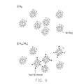
- FIG. 6 schematically shows a reaction mechanism between the magnetic nanoparticles coated with bio-probe and the bio-molecule to be measured, according to an embodiment of the present invention.
- FIG. 7 schematically shows a structure of magnetic nanoparticles coated with bio-probe, according to an embodiment of the present invention.
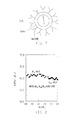
- FIG. 8 schematically shows a reaction expressed by the magnetization as a function of a time, according to an embodiment of the present invention.
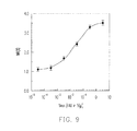
- FIG. 9 schematically shows a behavior of IMR(%) versus a virus concentration, according to an embodiment of the present invention.
- FIG. 10 schematically shows a behavior of IMR nor (%) in normalization versus a concentration of bio-molecule, according to an embodiment of the present invention.
- the present invention proposes to use a mixed-frequency excitation technology and the compensation mechanism in the electronic circuit.
- FIG. 3 schematically shows an architecture to measure the magnetization of magnetic fluid under an ac magnetic field, according to an embodiment of the present invention.
- FIG. 3 the example producing the mixed-frequency excitation from two frequencies is illustrated.
- the two excitation solenoids 204, 206 are respectively driven by ac current generators 200, 202 as a driving unit.
- the two ac current generators 200, 202 provide currents having different frequencies f 1 and f 2 separately to these two excitation solenoids 204, 206.
- Eq. (6) reveals the fact that M is a combination of components having frequencies ⁇ f 1 , ⁇ f 2 , and ⁇ f 1 + ⁇ f 2 , where ⁇ is positive odd integers, and ⁇ and ⁇ are non-zero integers.
- the pick-up solenoid 208 and the magnetic fluid 212 can be like the pick-up solenoid 104 and the magnetic fluid 108 in FIG. 1 , for example.
- the coil 210 can be formed by solenoids 204, 206, and 208. It is clear that, in addition to the odd sub-harmonic frequencies of f 1 and f 2 , the components having such frequencies as the linear combinations of f 1 and f 2 can be relating to the magnetization of magnetic fluid under the mixed-frequency excitation.
- the base frequencies f 1 and f 2 are linear independent, the mixed-frequency components of the output signal from coil 210 are not be disturbed with the sub-harmonic effect in the electronic circuit 214 when these components are amplified with electronic circuit 214. Furthermore, by suitably selecting f 1 and f 2 , the target frequency ⁇ T f 1 + ⁇ T f 2 can be far away from those popularly used in telecommunication, city electric power system, etc. Thus, the contribution from ambience can be prevented to the component of ⁇ T f 1 + ⁇ T f 2 for the magnetization of magnetic fluid under mixed-frequency excitation.
- the electronic circuit 214 needs to be designed to amplify the signals of components of ⁇ f 1 + ⁇ f 2 .
- the sub-harmonic components i.e. ⁇ f 1 and ⁇ f 2
- a compensation mechanism in the electronic circuit 214 is included to cancel the components of ⁇ f 1 and ⁇ f 2 .
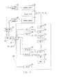
- the block diagram of the electronic circuit designed here is shown in FIG. 4 .
- the electronic circuit in FIG. 4 also includes the circuit for triggering ac current generators.
- the triggering signals having frequencies f 1 and f 2 respectively are generated with DSP, which signals are digital type and are converted to analog type through digital-to-analog converter (DAC) 252.
- the analog triggering signals f 1 and f 2 make ac current generators 200 and 202 to provide an ac current having frequency f 1 to excitation solenoid 1 204 and an ac current having frequency f 2 to excitation solenoid 2 206 via a power amplifier 254.
- the output signals from the gradiometer-type pick-up solenoid 208 are composed of frequencies of ⁇ f 1 , ⁇ f 2 , and ⁇ f 1 + ⁇ f 2 . All of these components are processed with the filtering/amplifying/compensating in the electronic circuit 214 to produce the target component at the mixed frequency ⁇ T f 1 + ⁇ T f 2 , ⁇ T and ⁇ T are positive integers. Generally, different choice to the ⁇ T and ⁇ T to obtain the mixed frequency may have different strength of signal being extracted out.
- the mixed frequency ⁇ T f 1 + ⁇ T f 2 is a general condition and the quantities of ⁇ T and ⁇ T are the design choices.
- FIG. 4 schematically shows a circuit block diagram for measuring the magnetization of magnetic fluid, according to an embodiment of the present invention.
- the apparatus in FIG. 3 can be shown in electronic block diagram.
- the electronic circuit 214 in FIG. 3 includes the circuit 260, which includes a digital signal processing (DSP) unit 250, amplifiers 262, 270, 280, filters 264, 272, 274, 282, ADC's 266, 276, 284 and digital-to-analog converters (DAC's) 268, 278, form at least one stage to perform functions of filtering, amplifying, and compensation.
- DSP digital signal processing
- DAC's digital-to-analog converters
- Each filtering/amplifying/compensating part has the amplification factor from 1 to 1000 where 1 means no amplifier being used.
- For each unit there is an amplifier and a bandpass filter with a center frequency at the target frequency.
- the DSP unit 250 provides the harmonic frequencies of f 1 and f 2 as the base frequencies per design choice.
- the frequencies of f 1 and f 2 is converted into analog signal by the DAC 252 to inform the power amplifier 254 to control the ac current generators 200 and 202 for producing ac currents.
- the two excitation solenoids 204 and 206 are driven by the ac currents with different base frequencies of f 1 and f 2 .
- the pick-up solenoid 208 with the magnetic fluid induces the signal spectrum with various resonant components at frequency of ⁇ f 1 , ⁇ f 2 , and ⁇ f 1 + ⁇ f 2 , ⁇ , ⁇ and ⁇ are positive integers, in which one of the components of ⁇ f 1 + ⁇ f 2 is to be extracted out and amplified as the target frequency ⁇ T f 1 + ⁇ T f 2 .
- the signals of components of ⁇ f 1 , ⁇ f 2 , and ⁇ f 1 + ⁇ f 2 from the pick-up solenoid 208 are input to the 1 st stage amplifier (AMP 1) 262. All of these components are amplified. However, the filter 1 264 with a central filtering frequency around the target frequency ⁇ T f 1 + ⁇ T f 2 filters the other signal components.
- the 1 st ADC 1A 266 converts analog signal into digital signal, which is input to the DSP 250 for finding amplitudes and phases of ⁇ f 1 and ⁇ f 2 , especially ⁇ f 1 and ⁇ f 2 near the central frequency, ⁇ T f 1 + ⁇ T f 2 .
- the DSP unit 250 To compensate (or offset) the components of ⁇ f 1 and ⁇ f 2 , the DSP unit 250 generates out-of-phase signals of ⁇ f 1 and ⁇ f 2 to cancel the components of ⁇ f 1 and ⁇ f 2 of amplified signals via a digital-to-analog converter DAC 1B 268.
- the 1 st -stage output signal and the out-of-phase signals of ⁇ f 1 and ⁇ f 2 of the DAC 1B 268 are output to the 2 nd -stage amplifier 270, in which the out-of-phase signals can be, for example, an invert phase so as to suppress the other signal component other than the target signal component with the frequency of ⁇ T f 1 + ⁇ T f 2 .
- the relative amplitude of ⁇ T f 1 + ⁇ T f 2 with respect to other components increases.
- the amplitudes of ⁇ f 1 and ⁇ f 2 are not significantly amplified, and may even be reduced due to the compensation process.
- the sub-harmonic effect of electronic circuit is also suppressed.
- cascading filtering/amplifying/compensating units the component of target frequency ⁇ T f 1 + ⁇ T f 2 can be greatly amplified.
- the final output signal of all components of ⁇ f 1 , ⁇ f 2 , and ⁇ f 1 + ⁇ f 2 is led to DSP via ADC nA 284.
- the amplitude of the target component at ⁇ T f 1 + ⁇ T f 2 is analyzed and output from DSP unit 250.
- the sample to be detected is water-based dextran coated Fe 3 O 4 magnetic fluid in this example, as to be described in FIG. 7 .
- the other materials such as MnFe 2 O 4 , CoFe 2 O 4 , Fe 2 O 3 , ..., and so on, can also be used for magnetic nanoparticles.
- Other hydrophilic material such as protein A, protein G, etc. can be used to replace dextran coated onto the surface of magnetic nanoparticles.
- the mean diameter of magnetic nanoparticles in magnetic fluid is 56 nm for this example.
- the mean diameter of magnetic nanoparticles are not limited to 56 nm. General speaking, the mean diameter of magnetic nanoparticles can range from 5 nm to 500 nm.
- the frequencies of f 1 and f 2 can vary from 10 Hz to 10 6 Hz, for example.
- the output amplitude of target component at ⁇ T f 1 + ⁇ T f 2 is measured by using the filtering/amplifying/compensating electronic circuit in Fig. 4 for magnetic fluids of various concentrations from zero to 0.3 emu/g, or even to higher concentrations.
- FIG. 5 schematically shows a relationship between magnetization versus concentration in a sample to be measured.
- the magnetic fluids in various concentrations from zero to 0.3 emu/g, are measured by the apparatus in FIG. 3 . It is noted that the highest concentration of magnetic fluid under detection is not limited to 0.3 emu/g. The higher the concentration is, the more the individual magnetic nanoparticles exist in magnetic fluid. It is expected that the magnetization M T of the target component at ⁇ T f 1 + ⁇ T f 2 increases as the concentration of magnetic fluid increases in a linear relation.
- the apparatus in FIG. 3 with the circuit architecture in FIG. 4 can have various applications, such as assay on bio-molecules via immunomagnetic reduction.
- the M T become less as the concentration of magnetic fluid, i.e. the number of individual magnetic nanoparticles in liquid, is reduced.
- the apparatus of the present invention can precisely measure the magnetization of the magnetic fluid and observe the variation. By utilizing this property, a method to detect bio-molecules in liquid is developed. In such method, bio-probes like anti-bodies are coated onto magnetic nanoparticles.
- FIG. 6 schematically shows a reaction mechanism between the magnetic nanoparticles coated with bio-probe and the bio-molecule to be measured, according to an embodiment of the present invention.
- the magnetic nanoparticles are specifically bio-functionalized and are able to associate with target bio-molecules. Due to the association, portion of individual bio-functionalized magnetic nanoparticles become physically larger or clustered.
- the magnetization is the initial state at M T,o .
- the magnetic nanoparticles are small and the rotation is easier.
- the magnetization M T, ⁇ of the sample is supposed to be less than that of the initial state M T,o , when bio-functionalized magnetic nanoparticles bind with target bio-molecules in magnetic fluid. This is the mechanism to perform assay method as ImmunoMganetic Reduction (IMR).
- IMR ImmunoMganetic Reduction
- FIG. 7 schematically shows a structure of magnetic nanoparticles coated with bio-probe, according to an embodiment of the present invention.
- bio-probe or antibody
- the magnetic nanoparticle is coated with dextran and then bio-probe (or antibody), such as polyclonal anti-H1N2 is used in this example.
- bio-probe or antibody
- monoclonal antibodies can also be used for bio-probe.
- the H1N2 is one of swine-influenza viruses as the bio-molecule to be detected in amount.
- FIG. 8 shows a reaction expressed by the magnetization as a function of a time, according to an embodiment of the present invention.
- the round dots denote the M T of the mixture of magnetic reagent and H1N2 solution before incubation.
- the dots distributed at a stable state in time The M T before incubation is denoted with M T,o .
- the time-average value is taken for the collected data 2 hours for example.
- the M T,o is measured as 66.18 under the target mixed frequency of ⁇ T f 1 + ⁇ T f 2 .
- the cross dots correspond to the processes that the bio-functionalized magnetic nanoparticles are binding with target bio-molecules H1N2. After the binding/incubation at room temperature, such as 22 °C.
- the M T, ⁇ represents the averaged M T for the data after the mixture of magnetic reagent and H1N2 solution has been incubated and reached to another stable state, as shown with square dots.
- the cross dots represent the transition state. As described in FIG.
- the magnetization M T, ⁇ becomes smaller after a sufficient incubation time.
- the incubation time generally depends on the quality of bio-probe and the incubation temperature.
- the incubation temperature can be, for example, from 18 °C to 45 °C and the incubation time can be, for example, 1 minute to 5 hours. If the incubation temperature is increased, the incubation time is expected to be reduced.
- the time-average value of the square dots is around 64.54 for M T, ⁇ .
- the significant reduction in M T evidences the conjugation between bio-functionalized magnetic nanoparticles and bio-molecules H1N2.
- the mean value and the standard deviation are 2.48 % and 0.09 %, respectively. The result approves the presumption made in the present invention.
- FIG. 9 shows a behavior of IMR(%) versus a virus concentration, according to an embodiment of the present invention.
- the relationship between IMR and the concentration of target bio-molecules, such as virus of H1N2 in this example is investigated.
- concentrations lower than 3x10 -4 HAU/50- ⁇ l IMR signals are near the noise level of the detecting device.
- concentration of H1N2 is higher than 3x10 -4 HAU/50- ⁇ l
- IMR signal increases exponentially with the increasing concentration of H1N2, and then almost reaches to a saturated value at high concentrations.
- IMR % A - B 1 + ⁇ ⁇ o ⁇ + B
- the parameter A in Eq. (8) corresponds to the noise level of this assay and B denotes the saturated IMR signal at high concentrated target bio-molecules.
- A, B, ⁇ o , and ⁇ can be found as 1.06, 3.65, 0.024, and 0.64, respectively.
- the correlation coefficient R 2 is 0.997 for that in FIG. 9 . So, the measured quantity of IMR as a function of concentration ⁇ of bio-molecule to be detected is very high and is well defined by Eq. (8).
- the logistic behavior expressed with Eq. (8) for the IMR- ⁇ o curve is found not only H1N2, but also for other kinds of bio-molecules.
- the bio-molecules can include, for example, proteins, viruses, nuclei acids, and even chemicals.
- the parameters A, B, ⁇ o , and ⁇ may vary for different kinds of target bio-molecules.
- an universal curve for IMR- ⁇ o relationships of different bio-molecules or chemicals by scaling IMR to (IMR-A)/(B-A), and ⁇ to ⁇ / ⁇ o can describe various samples in the same curve in Eq. (8), which is further expressed into Eq. (9):
- FIG. 10 schematically shows a behavior of IMR nor in normalization versus a normalized concentration of bio-molecules, according to an embodiment of the present invention.
- IMR nor (%) titled in the y axis in FIG. 10 is (IMR-A)/(B-A) in unit of percents.
- Eq. (9) can be the general curve to describe various bio-molecules.
- the concentration ⁇ of the bio-molecule to-be-detected can be obtained, according to Eq. (8) or Eq. (9) and a prepared table.
- the bio-probe provider may prepare the parameter table based on Eq. (8) or Eq. (9), so that the user can simply measure the concentration of the bio-molecule by measuring the quantities IMR.
- the measuring apparatus can be, for example, the apparatus in FIG. 3 and FIG. 4 with solenoids to produce ac magnetic field at the mixed frequency.
- the quantities IMR may be measured by other manner without limited to the solenoid-base.
- the apparatus in FIG. 3 and FIG. 4 is not the only choice in the present invention to measure the IMR.
Landscapes
- Health & Medical Sciences (AREA)
- Life Sciences & Earth Sciences (AREA)
- Engineering & Computer Science (AREA)
- Immunology (AREA)
- Chemical & Material Sciences (AREA)
- Molecular Biology (AREA)
- Biomedical Technology (AREA)
- Hematology (AREA)
- Urology & Nephrology (AREA)
- General Health & Medical Sciences (AREA)
- Nanotechnology (AREA)
- Physics & Mathematics (AREA)
- Medicinal Chemistry (AREA)
- Analytical Chemistry (AREA)
- Biochemistry (AREA)
- General Physics & Mathematics (AREA)
- Pathology (AREA)
- Biotechnology (AREA)
- Microbiology (AREA)
- Cell Biology (AREA)
- Food Science & Technology (AREA)
- Crystallography & Structural Chemistry (AREA)
- Chemical Kinetics & Catalysis (AREA)
- Bioinformatics & Cheminformatics (AREA)
- Pharmacology & Pharmacy (AREA)
- Medical Informatics (AREA)
- General Engineering & Computer Science (AREA)
- Biophysics (AREA)
- Electrochemistry (AREA)
- Investigating Or Analyzing Materials By The Use Of Magnetic Means (AREA)
- Measuring Or Testing Involving Enzymes Or Micro-Organisms (AREA)
Applications Claiming Priority (1)
| Application Number | Priority Date | Filing Date | Title |
|---|---|---|---|
| US12/394,043 US8193804B2 (en) | 2005-11-16 | 2009-02-27 | Device for measuring AC magnetization of materials |
Publications (2)
| Publication Number | Publication Date |
|---|---|
| EP2224236A1 true EP2224236A1 (de) | 2010-09-01 |
| EP2224236B1 EP2224236B1 (de) | 2011-10-26 |
Family
ID=42224414
Family Applications (1)
| Application Number | Title | Priority Date | Filing Date |
|---|---|---|---|
| EP10154646A Active EP2224236B1 (de) | 2009-02-27 | 2010-02-25 | Vorrichtung zum Messen der Wechselstrommagnetisierung von Materialien und Verfahren zur Erkennung von Biomolekülen |
Country Status (6)
| Country | Link |
|---|---|
| US (1) | US8193804B2 (de) |
| EP (1) | EP2224236B1 (de) |
| JP (1) | JP5243472B2 (de) |
| CN (1) | CN101819180B (de) |
| AT (1) | ATE530898T1 (de) |
| TW (1) | TWI412743B (de) |
Cited By (1)
| Publication number | Priority date | Publication date | Assignee | Title |
|---|---|---|---|---|
| CN116448817A (zh) * | 2023-03-10 | 2023-07-18 | 甘肃省科学院传感技术研究所 | 一种生物磁珠的快速检测系统及检测方法 |
Families Citing this family (20)
| Publication number | Priority date | Publication date | Assignee | Title |
|---|---|---|---|---|
| US7878071B2 (en) * | 2006-12-22 | 2011-02-01 | California Institute Of Technology | Nanoindenter tip for uniaxial tension and compression testing |
| US9427186B2 (en) * | 2009-12-04 | 2016-08-30 | Endomagnetics Ltd. | Magnetic probe apparatus |
| US10634741B2 (en) * | 2009-12-04 | 2020-04-28 | Endomagnetics Ltd. | Magnetic probe apparatus |
| CN102141540B (zh) * | 2010-12-31 | 2012-07-25 | 中国科学院物理研究所 | 一种测量纳米磁性液体交流磁化率的装置和方法 |
| RU2602731C1 (ru) * | 2012-12-10 | 2016-11-20 | Арселормитталь Инвестигасьон И Десарролло Сл | Способ и устройство для определения состояния и остающегося срока службы труб риформера из аустенитной стали и т.п. |
| CN105283202B (zh) | 2013-03-11 | 2019-04-23 | 安都磁学有限公司 | 用于淋巴结检测的低渗溶液 |
| US9239314B2 (en) | 2013-03-13 | 2016-01-19 | Endomagnetics Ltd. | Magnetic detector |
| CA2905313C (en) * | 2013-03-13 | 2020-09-22 | Endomagnetics Ltd. | Magnetic detector |
| US9234877B2 (en) | 2013-03-13 | 2016-01-12 | Endomagnetics Ltd. | Magnetic detector |
| CN110426436B (zh) | 2013-03-14 | 2022-08-19 | 安晟信医疗科技控股公司 | 分析物浓度测定的系统误差补偿 |
| CN104237526B (zh) * | 2013-06-18 | 2016-08-17 | 磁量生技股份有限公司 | 一种检测阿兹海默症罹患风险的系统 |
| ES2833377T3 (es) | 2015-06-04 | 2021-06-15 | Endomagnetics Ltd | Materiales marcadores y formas de localizar un marcador magnético |
| FR3038060B1 (fr) * | 2015-06-26 | 2018-11-02 | Atware | Appareil de mesure d'une quantite de materiau superparamagnetique |
| BE1023946B1 (fr) * | 2016-03-14 | 2017-09-19 | Safran Aero Boosters Sa | Capteur de particules dans un fluide d'un systeme de lubrification |
| WO2018023033A1 (en) | 2016-07-29 | 2018-02-01 | Western Michigan University Research Foundation | Magnetic nanoparticle-based gyroscopic sensor |
| CN107462847A (zh) * | 2017-06-27 | 2017-12-12 | 中国科学院电工研究所 | 一种磁纳米颗粒检测装置 |
| FR3100616B1 (fr) * | 2019-09-06 | 2021-09-17 | Magnisense Se | Dispositif de mesure comportant un générateur de champ magnétique et procédé de mesure associé |
| US12480934B1 (en) * | 2020-10-23 | 2025-11-25 | Mary Hitchcock Memorial Hospital, For Itself And On Behalf Of Dartmouth-Hitchcock Clinic | System and method for monitoring molecular agents in vivo by estimating magnetic nanoparticle aggregation |
| CN115266501A (zh) * | 2022-07-21 | 2022-11-01 | 上海交通大学 | 一种基于混频检测原理的浓度检测传感器 |
| CN116840094A (zh) * | 2023-07-13 | 2023-10-03 | 上海交通大学 | 一种磁标记生物分子检测方法及测量系统 |
Citations (3)
| Publication number | Priority date | Publication date | Assignee | Title |
|---|---|---|---|---|
| EP1262766A2 (de) * | 2000-03-09 | 2002-12-04 | Petr Ivanovich Nikitin | Analyse von biologischen und/oder chemischen gemischen unter verwendung von magnetischen teilchen |
| US20070111330A1 (en) * | 2005-11-16 | 2007-05-17 | Chin-Yih Rex Hong | Methods of quantitatively measuring biomolecules |
| US20070155024A1 (en) * | 2003-02-28 | 2007-07-05 | Peter Miethe | Method and device for selectively detecting ferromagnetic or superparamagnetic particles. |
Family Cites Families (7)
| Publication number | Priority date | Publication date | Assignee | Title |
|---|---|---|---|---|
| US5001424A (en) * | 1989-02-03 | 1991-03-19 | Product Resources, Inc. | Apparatus for measuring magnetic particles suspended in a fluid based on fluctuations in an induced voltage |
| CA2128861A1 (en) * | 1992-01-31 | 1993-08-05 | William R. Sheppard | Arrayed eddy current probe system |
| GB2324154B (en) * | 1997-04-01 | 2001-05-02 | Michael John Hutchings | Electromagnetic detector for measuring magnetic or conductive properties |
| ES2230430T3 (es) * | 2002-07-25 | 2005-05-01 | Amepa Angewandte Messtechnik Und Prozessautomatisierung Gmbh | Procedimiento y dispositivo para valorar señales de medicion de corriente parasita. |
| US7148678B1 (en) * | 2003-03-26 | 2006-12-12 | Targosz Thomas C | Magnetic taggant system |
| JP4680587B2 (ja) * | 2004-12-28 | 2011-05-11 | 旭化成株式会社 | バイオセンサ、対象物測定方法、バイオセンサ用カートリッジ及び不織布 |
| US20070111331A1 (en) * | 2005-11-16 | 2007-05-17 | Chin-Yih Rex Hong | Diagnostic methods using magnetic nanoparticles |
-
2009
- 2009-02-27 US US12/394,043 patent/US8193804B2/en active Active
-
2010
- 2010-01-08 TW TW099100363A patent/TWI412743B/zh active
- 2010-02-25 EP EP10154646A patent/EP2224236B1/de active Active
- 2010-02-25 AT AT10154646T patent/ATE530898T1/de not_active IP Right Cessation
- 2010-02-26 JP JP2010043213A patent/JP5243472B2/ja active Active
- 2010-02-26 CN CN2010101262183A patent/CN101819180B/zh active Active
Patent Citations (3)
| Publication number | Priority date | Publication date | Assignee | Title |
|---|---|---|---|---|
| EP1262766A2 (de) * | 2000-03-09 | 2002-12-04 | Petr Ivanovich Nikitin | Analyse von biologischen und/oder chemischen gemischen unter verwendung von magnetischen teilchen |
| US20070155024A1 (en) * | 2003-02-28 | 2007-07-05 | Peter Miethe | Method and device for selectively detecting ferromagnetic or superparamagnetic particles. |
| US20070111330A1 (en) * | 2005-11-16 | 2007-05-17 | Chin-Yih Rex Hong | Methods of quantitatively measuring biomolecules |
Non-Patent Citations (2)
| Title |
|---|
| HONG CHIN-YIH ET AL: "Wash-free immunomagnetic detection for serum through magnetic susceptibility reduction", APPLIED PHYSICS LETTERS, AIP, AMERICAN INSTITUTE OF PHYSICS, MELVILLE, NY, US LNKD- DOI:10.1063/1.2536127, vol. 90, no. 7, 13 February 2007 (2007-02-13), pages 74105 - 074105, XP012096097, ISSN: 0003-6951 * |
| KRAUSE ET AL: "Magnetic particle detection by frequency mixing for immunoassay applications", JOURNAL OF MAGNETISM AND MAGNETIC MATERIALS, ELSEVIER SCIENCE PUBLISHERS, AMSTERDAM, NL LNKD- DOI:10.1016/J.JMMM.2006.10.1164, vol. 311, no. 1, 15 March 2007 (2007-03-15), pages 436 - 444, XP022036705, ISSN: 0304-8853 * |
Cited By (1)
| Publication number | Priority date | Publication date | Assignee | Title |
|---|---|---|---|---|
| CN116448817A (zh) * | 2023-03-10 | 2023-07-18 | 甘肃省科学院传感技术研究所 | 一种生物磁珠的快速检测系统及检测方法 |
Also Published As
| Publication number | Publication date |
|---|---|
| JP5243472B2 (ja) | 2013-07-24 |
| US20090164161A1 (en) | 2009-06-25 |
| TW201031915A (en) | 2010-09-01 |
| TWI412743B (zh) | 2013-10-21 |
| CN101819180A (zh) | 2010-09-01 |
| ATE530898T1 (de) | 2011-11-15 |
| EP2224236B1 (de) | 2011-10-26 |
| CN101819180B (zh) | 2012-07-25 |
| US8193804B2 (en) | 2012-06-05 |
| JP2010204101A (ja) | 2010-09-16 |
Similar Documents
| Publication | Publication Date | Title |
|---|---|---|
| EP2224236B1 (de) | Vorrichtung zum Messen der Wechselstrommagnetisierung von Materialien und Verfahren zur Erkennung von Biomolekülen | |
| US12510613B2 (en) | Superparamagnetic particle imaging and its applications in quantitative multiplex stationary phase diagnostic assays | |
| Lee et al. | Recent developments in magnetic diagnostic systems | |
| US20030169032A1 (en) | Method and arrangement relating to substance analysis | |
| EP1421382B1 (de) | Verfahren und anordnung zur analyse von substanzen | |
| US9958516B2 (en) | Biological detector and method | |
| Vogel et al. | Critical Offset Magnetic PArticle SpectroScopy for rapid and highly sensitive medical point-of-care diagnostics | |
| US20100209299A1 (en) | Method of analysis of a mixture of biological and/or chemical components with the use magnetic particles and apparatus for its embodiment | |
| US20030076087A1 (en) | Method and arrangement relating to substance analysis | |
| US9482643B2 (en) | Means and methods using paramagnetic agents for in vitro diagnostic applications | |
| Malhotra et al. | Tracking the growth of superparamagnetic nanoparticles with an in-situ magnetic particle spectrometer (INSPECT) | |
| Demas et al. | Magnetic resonance for in vitro medical diagnostics: superparamagnetic nanoparticle-based magnetic relaxation switches | |
| Gordon-Wylie et al. | Measuring protein biomarker concentrations using antibody tagged magnetic nanoparticles | |
| Sun et al. | A multi-frequency magnetic particle spectroscopy system for systematic characterization and highly sensitive detection of magnetic nanoparticles | |
| JP4669259B2 (ja) | 被検物質分析装置及び定量方法 | |
| Park et al. | Multiplexed sensing based on Brownian relaxation of magnetic nanoparticles using a compact AC susceptometer | |
| Wolgast et al. | Low-cost Magnetic Particle Spectroscopy hardware for low-viral-load immunoassays | |
| Hong et al. | Magnetic immunoassay based on frequency mixing magnetic detection and magnetic particles of different magnetic properties | |
| CN103760186A (zh) | 用于体外诊断应用的使用顺磁剂的工具和方法 | |
| US20130224073A1 (en) | Device for detection of magnetic nanoparticle aggregation or disaggregation | |
| US11366050B1 (en) | Ultra-sensitive volumetric magnetic particle detector | |
| Sack et al. | Functional magnetic nanoparticles: from synthesis design to in-depth characterization and nano-labelling for ultrasensitive magnetic biosensing | |
| Salvador Fernández | Biofunctional nanoparticles for magnetic immunoassays: application to the detection of pneumolysin for the rapid diagnosis of pneumococcal pneumonia. | |
| KR20250045689A (ko) | 자기 코일에 기반하는 측면 유동 검사 시스템 및 그 동작방법 | |
| Petralia et al. | Magnetic Beads Compatibility as DNA Hybridization Labels in Integrated Thermal-Magnetic Biosensor |
Legal Events
| Date | Code | Title | Description |
|---|---|---|---|
| PUAI | Public reference made under article 153(3) epc to a published international application that has entered the european phase |
Free format text: ORIGINAL CODE: 0009012 |
|
| 17P | Request for examination filed |
Effective date: 20100225 |
|
| AK | Designated contracting states |
Kind code of ref document: A1 Designated state(s): AT BE BG CH CY CZ DE DK EE ES FI FR GB GR HR HU IE IS IT LI LT LU LV MC MK MT NL NO PL PT RO SE SI SK SM TR |
|
| AX | Request for extension of the european patent |
Extension state: AL BA RS |
|
| 17Q | First examination report despatched |
Effective date: 20101129 |
|
| GRAP | Despatch of communication of intention to grant a patent |
Free format text: ORIGINAL CODE: EPIDOSNIGR1 |
|
| RIC1 | Information provided on ipc code assigned before grant |
Ipc: G01N 33/543 20060101ALI20110408BHEP Ipc: G01N 27/74 20060101AFI20110408BHEP Ipc: G01N 33/53 20060101ALI20110408BHEP |
|
| GRAS | Grant fee paid |
Free format text: ORIGINAL CODE: EPIDOSNIGR3 |
|
| GRAA | (expected) grant |
Free format text: ORIGINAL CODE: 0009210 |
|
| AK | Designated contracting states |
Kind code of ref document: B1 Designated state(s): AT BE BG CH CY CZ DE DK EE ES FI FR GB GR HR HU IE IS IT LI LT LU LV MC MK MT NL NO PL PT RO SE SI SK SM TR |
|
| REG | Reference to a national code |
Ref country code: GB Ref legal event code: FG4D |
|
| REG | Reference to a national code |
Ref country code: CH Ref legal event code: EP |
|
| REG | Reference to a national code |
Ref country code: IE Ref legal event code: FG4D |
|
| REG | Reference to a national code |
Ref country code: DE Ref legal event code: R096 Ref document number: 602010000300 Country of ref document: DE Effective date: 20120105 |
|
| REG | Reference to a national code |
Ref country code: NL Ref legal event code: T3 |
|
| LTIE | Lt: invalidation of european patent or patent extension |
Effective date: 20111026 |
|
| REG | Reference to a national code |
Ref country code: AT Ref legal event code: MK05 Ref document number: 530898 Country of ref document: AT Kind code of ref document: T Effective date: 20111026 |
|
| PG25 | Lapsed in a contracting state [announced via postgrant information from national office to epo] |
Ref country code: BE Free format text: LAPSE BECAUSE OF FAILURE TO SUBMIT A TRANSLATION OF THE DESCRIPTION OR TO PAY THE FEE WITHIN THE PRESCRIBED TIME-LIMIT Effective date: 20111026 Ref country code: NO Free format text: LAPSE BECAUSE OF FAILURE TO SUBMIT A TRANSLATION OF THE DESCRIPTION OR TO PAY THE FEE WITHIN THE PRESCRIBED TIME-LIMIT Effective date: 20120126 Ref country code: LT Free format text: LAPSE BECAUSE OF FAILURE TO SUBMIT A TRANSLATION OF THE DESCRIPTION OR TO PAY THE FEE WITHIN THE PRESCRIBED TIME-LIMIT Effective date: 20111026 Ref country code: IS Free format text: LAPSE BECAUSE OF FAILURE TO SUBMIT A TRANSLATION OF THE DESCRIPTION OR TO PAY THE FEE WITHIN THE PRESCRIBED TIME-LIMIT Effective date: 20120226 |
|
| PG25 | Lapsed in a contracting state [announced via postgrant information from national office to epo] |
Ref country code: PT Free format text: LAPSE BECAUSE OF FAILURE TO SUBMIT A TRANSLATION OF THE DESCRIPTION OR TO PAY THE FEE WITHIN THE PRESCRIBED TIME-LIMIT Effective date: 20120227 Ref country code: HR Free format text: LAPSE BECAUSE OF FAILURE TO SUBMIT A TRANSLATION OF THE DESCRIPTION OR TO PAY THE FEE WITHIN THE PRESCRIBED TIME-LIMIT Effective date: 20111026 Ref country code: SI Free format text: LAPSE BECAUSE OF FAILURE TO SUBMIT A TRANSLATION OF THE DESCRIPTION OR TO PAY THE FEE WITHIN THE PRESCRIBED TIME-LIMIT Effective date: 20111026 Ref country code: PL Free format text: LAPSE BECAUSE OF FAILURE TO SUBMIT A TRANSLATION OF THE DESCRIPTION OR TO PAY THE FEE WITHIN THE PRESCRIBED TIME-LIMIT Effective date: 20111026 Ref country code: SE Free format text: LAPSE BECAUSE OF FAILURE TO SUBMIT A TRANSLATION OF THE DESCRIPTION OR TO PAY THE FEE WITHIN THE PRESCRIBED TIME-LIMIT Effective date: 20111026 Ref country code: GR Free format text: LAPSE BECAUSE OF FAILURE TO SUBMIT A TRANSLATION OF THE DESCRIPTION OR TO PAY THE FEE WITHIN THE PRESCRIBED TIME-LIMIT Effective date: 20120127 Ref country code: LV Free format text: LAPSE BECAUSE OF FAILURE TO SUBMIT A TRANSLATION OF THE DESCRIPTION OR TO PAY THE FEE WITHIN THE PRESCRIBED TIME-LIMIT Effective date: 20111026 |
|
| PG25 | Lapsed in a contracting state [announced via postgrant information from national office to epo] |
Ref country code: CY Free format text: LAPSE BECAUSE OF FAILURE TO SUBMIT A TRANSLATION OF THE DESCRIPTION OR TO PAY THE FEE WITHIN THE PRESCRIBED TIME-LIMIT Effective date: 20111026 |
|
| PG25 | Lapsed in a contracting state [announced via postgrant information from national office to epo] |
Ref country code: SK Free format text: LAPSE BECAUSE OF FAILURE TO SUBMIT A TRANSLATION OF THE DESCRIPTION OR TO PAY THE FEE WITHIN THE PRESCRIBED TIME-LIMIT Effective date: 20111026 Ref country code: DK Free format text: LAPSE BECAUSE OF FAILURE TO SUBMIT A TRANSLATION OF THE DESCRIPTION OR TO PAY THE FEE WITHIN THE PRESCRIBED TIME-LIMIT Effective date: 20111026 Ref country code: EE Free format text: LAPSE BECAUSE OF FAILURE TO SUBMIT A TRANSLATION OF THE DESCRIPTION OR TO PAY THE FEE WITHIN THE PRESCRIBED TIME-LIMIT Effective date: 20111026 Ref country code: CZ Free format text: LAPSE BECAUSE OF FAILURE TO SUBMIT A TRANSLATION OF THE DESCRIPTION OR TO PAY THE FEE WITHIN THE PRESCRIBED TIME-LIMIT Effective date: 20111026 Ref country code: BG Free format text: LAPSE BECAUSE OF FAILURE TO SUBMIT A TRANSLATION OF THE DESCRIPTION OR TO PAY THE FEE WITHIN THE PRESCRIBED TIME-LIMIT Effective date: 20120126 |
|
| PG25 | Lapsed in a contracting state [announced via postgrant information from national office to epo] |
Ref country code: RO Free format text: LAPSE BECAUSE OF FAILURE TO SUBMIT A TRANSLATION OF THE DESCRIPTION OR TO PAY THE FEE WITHIN THE PRESCRIBED TIME-LIMIT Effective date: 20111026 |
|
| PLBE | No opposition filed within time limit |
Free format text: ORIGINAL CODE: 0009261 |
|
| STAA | Information on the status of an ep patent application or granted ep patent |
Free format text: STATUS: NO OPPOSITION FILED WITHIN TIME LIMIT |
|
| PG25 | Lapsed in a contracting state [announced via postgrant information from national office to epo] |
Ref country code: MC Free format text: LAPSE BECAUSE OF NON-PAYMENT OF DUE FEES Effective date: 20120229 |
|
| 26N | No opposition filed |
Effective date: 20120727 |
|
| REG | Reference to a national code |
Ref country code: DE Ref legal event code: R097 Ref document number: 602010000300 Country of ref document: DE Effective date: 20120727 |
|
| PG25 | Lapsed in a contracting state [announced via postgrant information from national office to epo] |
Ref country code: AT Free format text: LAPSE BECAUSE OF FAILURE TO SUBMIT A TRANSLATION OF THE DESCRIPTION OR TO PAY THE FEE WITHIN THE PRESCRIBED TIME-LIMIT Effective date: 20111026 |
|
| PG25 | Lapsed in a contracting state [announced via postgrant information from national office to epo] |
Ref country code: MK Free format text: LAPSE BECAUSE OF FAILURE TO SUBMIT A TRANSLATION OF THE DESCRIPTION OR TO PAY THE FEE WITHIN THE PRESCRIBED TIME-LIMIT Effective date: 20111026 |
|
| PG25 | Lapsed in a contracting state [announced via postgrant information from national office to epo] |
Ref country code: ES Free format text: LAPSE BECAUSE OF FAILURE TO SUBMIT A TRANSLATION OF THE DESCRIPTION OR TO PAY THE FEE WITHIN THE PRESCRIBED TIME-LIMIT Effective date: 20120206 |
|
| PG25 | Lapsed in a contracting state [announced via postgrant information from national office to epo] |
Ref country code: FI Free format text: LAPSE BECAUSE OF FAILURE TO SUBMIT A TRANSLATION OF THE DESCRIPTION OR TO PAY THE FEE WITHIN THE PRESCRIBED TIME-LIMIT Effective date: 20111026 |
|
| PG25 | Lapsed in a contracting state [announced via postgrant information from national office to epo] |
Ref country code: MT Free format text: LAPSE BECAUSE OF FAILURE TO SUBMIT A TRANSLATION OF THE DESCRIPTION OR TO PAY THE FEE WITHIN THE PRESCRIBED TIME-LIMIT Effective date: 20111026 |
|
| REG | Reference to a national code |
Ref country code: NL Ref legal event code: SD Effective date: 20131205 |
|
| REG | Reference to a national code |
Ref country code: DE Ref legal event code: R082 Ref document number: 602010000300 Country of ref document: DE Representative=s name: BECKER, KURIG, STRAUS, DE |
|
| REG | Reference to a national code |
Ref country code: FR Ref legal event code: TP Owner name: MAGQU CO., LTD., TW Effective date: 20131230 |
|
| REG | Reference to a national code |
Ref country code: DE Ref legal event code: R082 Ref document number: 602010000300 Country of ref document: DE Representative=s name: BECKER, KURIG, STRAUS, DE Effective date: 20140113 Ref country code: DE Ref legal event code: R081 Ref document number: 602010000300 Country of ref document: DE Owner name: MAGQU CO., LTD., TW Free format text: FORMER OWNER: CHIN-YIH REX HONG,HERNG-ER HORNG,HONG-CHANG YANG,SHIEH-YUEH YANG, , TW Effective date: 20140113 Ref country code: DE Ref legal event code: R081 Ref document number: 602010000300 Country of ref document: DE Owner name: MAGQU CO., LTD., TW Free format text: FORMER OWNERS: HONG, CHIN-YIH REX, TAIPEH/T'AI-PEI, TA TZE, TW; HORNG, HERNG-ER, TAIPAI/T'AI-PEI, TA TZE, TW; YANG, HONG-CHANG, TAIPEH/T'AI-PEI, TA TZE, TW; YANG, SHIEH-YUEH, TAIPEI, TW Effective date: 20140113 |
|
| PG25 | Lapsed in a contracting state [announced via postgrant information from national office to epo] |
Ref country code: TR Free format text: LAPSE BECAUSE OF FAILURE TO SUBMIT A TRANSLATION OF THE DESCRIPTION OR TO PAY THE FEE WITHIN THE PRESCRIBED TIME-LIMIT Effective date: 20111026 |
|
| PG25 | Lapsed in a contracting state [announced via postgrant information from national office to epo] |
Ref country code: SM Free format text: LAPSE BECAUSE OF FAILURE TO SUBMIT A TRANSLATION OF THE DESCRIPTION OR TO PAY THE FEE WITHIN THE PRESCRIBED TIME-LIMIT Effective date: 20111026 Ref country code: LU Free format text: LAPSE BECAUSE OF NON-PAYMENT OF DUE FEES Effective date: 20120225 |
|
| PG25 | Lapsed in a contracting state [announced via postgrant information from national office to epo] |
Ref country code: HU Free format text: LAPSE BECAUSE OF FAILURE TO SUBMIT A TRANSLATION OF THE DESCRIPTION OR TO PAY THE FEE WITHIN THE PRESCRIBED TIME-LIMIT Effective date: 20100225 |
|
| REG | Reference to a national code |
Ref country code: CH Ref legal event code: PL |
|
| PG25 | Lapsed in a contracting state [announced via postgrant information from national office to epo] |
Ref country code: LI Free format text: LAPSE BECAUSE OF NON-PAYMENT OF DUE FEES Effective date: 20140228 Ref country code: CH Free format text: LAPSE BECAUSE OF NON-PAYMENT OF DUE FEES Effective date: 20140228 |
|
| REG | Reference to a national code |
Ref country code: FR Ref legal event code: PLFP Year of fee payment: 7 |
|
| REG | Reference to a national code |
Ref country code: FR Ref legal event code: PLFP Year of fee payment: 8 |
|
| REG | Reference to a national code |
Ref country code: FR Ref legal event code: PLFP Year of fee payment: 9 |
|
| PGFP | Annual fee paid to national office [announced via postgrant information from national office to epo] |
Ref country code: NL Payment date: 20260223 Year of fee payment: 17 |
|
| PGFP | Annual fee paid to national office [announced via postgrant information from national office to epo] |
Ref country code: GB Payment date: 20260223 Year of fee payment: 17 |
|
| PGFP | Annual fee paid to national office [announced via postgrant information from national office to epo] |
Ref country code: DE Payment date: 20260224 Year of fee payment: 17 Ref country code: IE Payment date: 20260225 Year of fee payment: 17 |
|
| PGFP | Annual fee paid to national office [announced via postgrant information from national office to epo] |
Ref country code: IT Payment date: 20260226 Year of fee payment: 17 |
|
| PGFP | Annual fee paid to national office [announced via postgrant information from national office to epo] |
Ref country code: FR Payment date: 20260223 Year of fee payment: 17 |