EP2224997B1 - Medizinische implantierbare leitung und verfahren zur herstellung dieser leitung - Google Patents
Medizinische implantierbare leitung und verfahren zur herstellung dieser leitung Download PDFInfo
- Publication number
- EP2224997B1 EP2224997B1 EP07852124A EP07852124A EP2224997B1 EP 2224997 B1 EP2224997 B1 EP 2224997B1 EP 07852124 A EP07852124 A EP 07852124A EP 07852124 A EP07852124 A EP 07852124A EP 2224997 B1 EP2224997 B1 EP 2224997B1
- Authority
- EP
- European Patent Office
- Prior art keywords
- inner coil
- lead
- connector pin
- proximal end
- coil
- Prior art date
- Legal status (The legal status is an assumption and is not a legal conclusion. Google has not performed a legal analysis and makes no representation as to the accuracy of the status listed.)
- Ceased
Links
- 238000000034 method Methods 0.000 title claims abstract description 10
- 238000004519 manufacturing process Methods 0.000 title claims abstract description 6
- 210000000056 organ Anatomy 0.000 claims abstract description 21
- 238000012544 monitoring process Methods 0.000 claims abstract description 20
- 241001465754 Metazoa Species 0.000 claims abstract description 5
- 238000000429 assembly Methods 0.000 claims description 4
- 238000005520 cutting process Methods 0.000 claims description 4
- 238000007789 sealing Methods 0.000 description 8
- 238000004804 winding Methods 0.000 description 6
- 230000035515 penetration Effects 0.000 description 4
- 238000003780 insertion Methods 0.000 description 3
- 230000037431 insertion Effects 0.000 description 3
- 238000003466 welding Methods 0.000 description 3
- 230000000747 cardiac effect Effects 0.000 description 2
- 230000000694 effects Effects 0.000 description 2
- 238000004026 adhesive bonding Methods 0.000 description 1
- 238000005452 bending Methods 0.000 description 1
- 239000004020 conductor Substances 0.000 description 1
- 238000010292 electrical insulation Methods 0.000 description 1
- 239000012777 electrically insulating material Substances 0.000 description 1
- 239000012530 fluid Substances 0.000 description 1
- 238000002513 implantation Methods 0.000 description 1
- 239000002184 metal Substances 0.000 description 1
- 238000005476 soldering Methods 0.000 description 1
- 210000003462 vein Anatomy 0.000 description 1
Images


Classifications
-
- A—HUMAN NECESSITIES
- A61—MEDICAL OR VETERINARY SCIENCE; HYGIENE
- A61N—ELECTROTHERAPY; MAGNETOTHERAPY; RADIATION THERAPY; ULTRASOUND THERAPY
- A61N1/00—Electrotherapy; Circuits therefor
- A61N1/02—Details
- A61N1/04—Electrodes
- A61N1/05—Electrodes for implantation or insertion into the body, e.g. heart electrode
- A61N1/056—Transvascular endocardial electrode systems
-
- Y—GENERAL TAGGING OF NEW TECHNOLOGICAL DEVELOPMENTS; GENERAL TAGGING OF CROSS-SECTIONAL TECHNOLOGIES SPANNING OVER SEVERAL SECTIONS OF THE IPC; TECHNICAL SUBJECTS COVERED BY FORMER USPC CROSS-REFERENCE ART COLLECTIONS [XRACs] AND DIGESTS
- Y10—TECHNICAL SUBJECTS COVERED BY FORMER USPC
- Y10T—TECHNICAL SUBJECTS COVERED BY FORMER US CLASSIFICATION
- Y10T29/00—Metal working
- Y10T29/49—Method of mechanical manufacture
- Y10T29/49002—Electrical device making
- Y10T29/49117—Conductor or circuit manufacturing
- Y10T29/49204—Contact or terminal manufacturing
- Y10T29/49208—Contact or terminal manufacturing by assembling plural parts
Definitions
- the invention relates to a medical implantable lead being adapted to be inserted into a human or animal body and attached to an organ inside the body for monitoring and/or controlling the function of the organ, comprising a header in a distal end, a fixation means and an electrode arranged in the header, wherein the fixation means is arranged to attach the distal end of the lead to the organ and the electrode is arranged to transmit or receive electrical signals to or from the organ, a connector in a proximal end which includes a connector pin and is adapted to be connected to a monitoring and/or controlling device, and an inner coil, which extends inside an outer casing of the lead and is adapted to transmit electrical signals between the monitoring and/or controlling device and the electrode, wherein the inner coil is attached to the connector pin.
- the invention also relates to method for manufacturing of a medical implantable lead of the above kind.
- Medical implantable leads of the above kind are commonly used for example for monitoring and/or controlling the function of a human or animal heart.
- a proximal end of the lead is connected to a monitoring and/or controlling device such as a pacemaker or a cardiac defibrillator, whereas a distal end of the lead is inserted into the body and attached to the heart by means of some kind of fixation means.
- the distal end of the lead comprises at least one electrode, which is in electrical contact with the proximal end by means of an inner coil of helically formed metal wires inside the lead.
- the fixation means can be of a type having projections, such as fins or tines, which will engage in the trabecular network inside the heart.
- the fixation means can also be a penetration member, such as a barbed needle or as a helix which is screwed into the tissue of the heart, either as a helix which is unrotatable in relation to the lead, in which case the entire lead is rotated when attaching the helix, or a rotatable helix which can be rotated in relation to the lead from the proximal end by means of the inner coil, which is rotatably arranged inside the lead.
- a penetration member such as a barbed needle or as a helix which is screwed into the tissue of the heart, either as a helix which is unrotatable in relation to the lead, in which case the entire lead is rotated when attaching the helix, or a rotatable helix which can be rotated in relation to the lead from the proximal end by means of the inner coil, which is rotatably arranged inside the lead.
- a rotatable helix can be rotatable but non-extendable in relation to the lead, or it can be rotatable and extendable, in which case the helix is accommodated inside a sleeve formed header in the distal end of the lead and will be screwed out from the header when attaching it to the tissue. In the latter case the inner coil will accordingly be stretched out when attaching the helix to the tissue.
- the penetration member can also function as an electrode inside the tissue, in which case the penetration member is electrically connected to the inner coil, or be separated from the electrode, in which case the penetration member is not electrically connected to the inner coil.
- the inner coil is connected, mechanically as well as electrically, to a connector pin, which can be electrically connected to a monitoring and/or controlling device and which is accommodated in a connector housing.
- the connector pin is rotatably journalled inside the connector housing.
- the inner coil will have several functions. Firstly, it will function as an electrical conductor for transferring of electrical signals between the monitoring and/or controlling device and the electrode in the distal end.
- the inner coil shall also transfer rotary motion from the proximal to the distal end.
- the inner coil will also be elongated to maintain the mechanical as well as electrical contact with the helix during rotation and advancement.
- the inner coil shall contribute to the desired bending characteristics of the lead, i.e. the lead has to be flexible but should have sufficient stiffness to be insertable through a vein or the like.
- the inner coil will define an inner lumen in the lead, into which a guide wire or stylet may be inserted during implantation, for guiding the distal end of the lead to a suitably position abutting with its distal end against an organ inside the body and subsequent fixation by the fixation means, e.g. by screwing in of the helix into the organ.
- the inner wire coil is attached to the connector pin at a distal end portion of the connector pin.
- the inner coil be welded to the connector pin or be attached by means of a clamp connection, in which case a proximal portion of the inner wire coil often is thread onto a support tube to prevent collapsing of the coil section during clamping, and the support tube as well as the thread up portion of the inner coil is inserted into a bore from the distal end of the connector pin and fixated therein by clamping and deforming of the connector pin.
- the connector pin in prior art is normally provided with an enlarged bore in a distal portion to allow insertion and attachment of the inner coil inside the connector pin.
- a proximal portion of the connector pin is only provided with a small diameter bore to allow insertion of a guide wire or the like when implanting the lead into the body.
- the inner coil in practice functions as a helical spring and tensile stress will arise in the inner coil if the length is to short, since then it has to be stretched when attaching to the connector pin, with the potential risk that the helix will tend to rotate after attaching to the organ which can cause disengagement of the lead from the organ.
- the entire lead has to be discarded.
- the inner coil is attached to the connector pin, this can cause the coil windings to become uneven and wave shaped, which will increase the friction against an inner tubing, which encloses the inner coil and in relation to which the inner coil is rotatable.
- a medical implantable lead constructed in this way also has to be assembled by one component at a time from one of the ends of the lead. This has to effect that if one of all the components forming the medical implantable lead should fail or be incorrect mounted, the entire medical implantable lead has to be discarded.
- An object of the invention is to provide a medical implantable lead, which is possible to manufacture at a low cost, high quality and with improved helix performance. At least this object is achieved by a medical implantable lead according to claim 1.
- the invention also relates to a method having essentially the same object as above. At least this object is achieved by a method according to claim 6.
- the basis of the invention is the understanding that this object can be achieved by letting the inner coil extend through the entire connector pin and to attach the inner coil at the proximal end of the connector pin.
- the length of the inner coil can be cut as one of the last operations of the assembling of the medical implantable lead. Accordingly, the cut length of the inner coil can be adapted to the actual length due to the aggregate tolerances of the rest of the lead, such that the inner coil can be cut in a length that will not give any disadvantageous inherent tensions in the inner coil.
- any uneven windings of the inner coil caused by the attachment to the connector pin will be disposed inside the inner bore of the connector pin and, accordingly, can not cause any seizing in relation to the inner tubing of the lead in case of a rotatable inner coil.
- the initial length of the inner coil can be made in one size fitting all different lengths of medical implantable leads, which will reduce the number of pre-cutting fixtures. When the cutting of the inner coil is performed as one of the last operations, the possibility of getting rests of cut filaments inside the lead is reduced. It is also an advantage that the attachment of the inner coil to the connector pin will always be visible from the outside such that e.g. a weld connection can be easily verified.
- the inner coil can be directly attached to the proximal end of the connector pin, e.g. by welding.
- the inner coil is attached to the connector pin via a coil adapter having a shaft portion with a through lumen, onto which a few of the most proximal windings of the inner coil are thread and subsequently the coil adapter with the coil windings is inserted into a recess in the proximal end of the connector pin and attached, while a head of the coil adapter will remain on the outside of or flush with the proximal end of the connector pin.
- the attachment between the inner coil and the coil adapter as well as between the coil adapter and the connector pin can be performed in many different ways, such as by welding, by laser or otherwise, soldering, crimp connection or adhesive bonding.
- the medical implantable lead into two different sub-assemblies, more precisely a first sub-assembly comprising the inner coil and a distal header comprising a fixation means, and a second sub-assembly comprising a casing defined by an outer tubing, an outer coil, optional a ring electrode, an inner tubing and a connector comprising the connector pin in a proximal end.
- a first sub-assembly comprising the inner coil and a distal header comprising a fixation means
- a second sub-assembly comprising a casing defined by an outer tubing, an outer coil, optional a ring electrode, an inner tubing and a connector comprising the connector pin in a proximal end.
- the free end of the inner coil of the first sub-assembly is inserted into the inner lumen defined by the outer tubing, the outer coil and the inner tubing of the second sub-assembly, until the inner coil projects from the proximal end of the connector pin and the distal ends of the outer tubing, outer coil and inner tubing abuts the proximal end of the header. Subsequently, the inner tubing, the outer coil and the outer tubing are attached in correct position to the header. At this stage the length of the lead is fixed. The only thing remaining is to cut the inner coil in length and attach the inner coil to the proximal end of the connector pin.
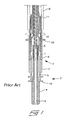
- fig 1 in which is illustrated, in a longitudinal section, a prior art embodiment of a proximal portion of a medical implantable lead.
- the lead is provided with a connector 2 for mechanical as well as electrical connection of the lead to a monitoring and/or controlling device, such as a pacemaker or a cardiac defibrillator.
- the connector 2 comprises a connector housing 3 in which a connector pin 4 is rotatably accommodated by being rotatable mounted in a bearing sleeve 5 inside the connector housing 3.
- the connector pin 4 is electrically conductive and is in its distal end connected, mechanically as well as electrically, to an inner coil 6 of helically wound metallic wires, e.g. by a clamp connection.
- the inner coil 6 is thread onto a support tube 1, which is inserted into a bore having an enlarged diameter in the distal portion of the connector pin 4. Subsequently, the distal portion of the connector pin is deformed by clamping such that the inner coil 6 is clamped between the connector pin 4 and the support tube 1. Where the enlarged diameter bore terminates, the bore transforms to a small diameter lumen adapted only for insertion of a guide wire or the like, when implanting the lead.
- the connector housing 3 is assembled of a proximal sealing member 7, an intermediate connector ring 8 and a distal sealing member 9. Both of the sealing members 7 and 9 are of an electrically insulating material and are provided with resilient sealing flanges 10 for allowing fluid tight connection to the monitoring and/or controlling device.
- the connector ring 8 is electrically conductive and is connected to an outer coil 11 of helically wound metallic wires.
- An inner tubing 12 is positioned between the inner coil 6 and the outer coil 11 for electrical insulation of the inner and outer coils in relation to each other.
- the inner coil 6 is also rotatable in respect of the inner tubing 12.
- a medical implantable lead according to the invention as well as according to a prior art embodiment, which is of a kind provided with a rotatable as well as extendable helix in the distal end for attachment to a heart by being screwed into the tissue of the heart.
- figs 2 and 3 are longitudinal sections of a distal portion of a medical implantable lead comprising a sleeve formed header 13 in the distal end.
- a helix 14 is accommodated inside the sleeve formed header, as is illustrated in fig 2 .
- the lead When the lead is correct positioned inside the body with its distal end abutting against an organ, the lead can be attached to the tissue by rotation of the inner coil 6, wherein the helix 14 will be screwed out from the header 13 and into the tissue, as is illustrated in fig 3 . Accordingly, the inner coil 6 will be slightly stretched out when extending the helix from the header. Visible in figs 2 and 3 are also the inner tubing 12, the outer coil 11 and an outer tubing 15 and their respective attachment to the header 13. The outer coil 11 is electrically connected to a ring electrode 16 on the outside of the header.
- the connector 2 comprises a connector housing 3 in which a connector pin 4 is rotatably accommodated by being rotatably mounted in a bearing sleeve 5.
- An inner coil 6 is mechanically and electrically connected to the connector pin 4.
- the connector housing 3 comprises a proximal sealing member 7, an intermediate connector ring 8 and a distal sealing member 9. Both the sealing members 7 and 9 is provided with sealing flanges 10.
- the connector ring 8 is connected to an outer coil 11 and an inner tubing 12 is arranged between the inner coil 6 and the outer coil 11 to insulate them electrically from each other.
- the inner tubing also allows rotation of the inner coil 6.
- an outer tubing is attached in the distal end of the connector 2.
- the attachment of the inner coil 6 to the connector pin 4 is in figs 4-6 performed in a different way in relation to the prior art embodiment in fig 1 . More precisely, instead of attaching the inner coil to the distal end of the connector pin, as in fig 1 , the connector pin is provided with an enlarged inner bore 17, such that the inner coil can be passed through the entire connector pin and attached in the proximal end of the same.
- a procedure for attaching the inner coil to the connector pin is illustrated in figs 4-6 .
- the connector 2 can preferably be assembled and connected to the inner tubing 12, the outer coil 11 and the outer tubing 15, as is illustrated in fig 4 .
- a guide wire 18 can preferably be inserted in the inner lumen of the inner coil 6 for stiffening of the latter.
- the inner coil 6 When the inner coil 6 is fully inserted such that an end of the inner coil projects from the proximal end of the connector 2, the inner coil can be cut to a desired length, as is illustrated in fig 5 . Subsequently, the proximal end of the inner coil is thread up on a coil adapter 19, as is illustrated in figs 5 and 6 .
- the coil adapter is provided with an inner lumen 20, a shaft portion 21 and a head portion 22. When mounting the inner coil, a few of the most proximal windings are thread up on the shaft portion 21 and fixated by means of e.g. laser welding.
- the coil adapter together with the inner coil is inserted into the inner bore 17 of the connector pin 4 which is formed with an enlarged portion in the proximal end to accommodate the shaft portion as well as the head portion of the coil adapter, such that the coil adapter will be positioned with its head portion flush with the proximal end of the connector pin.
- a new method for assembling the lead is made possible. More precisely, it is made possible to build up the lead as two separate sub-assemblies, which are combined as a last assembly step. This is illustrated in fig 7 , where a first sub-assembly 23 comprises the header 13, including the helix, and the inner coil 6 attached to the header.
- a second sub-assembly 24 is comprised of the connector 2 and an outer casing formed by the inner tubing 12, the outer coil 11 and the outer tubing 15. Before assembling, the respective sub-assembly may preferably be tested visually and functionally.
- the proximal end of the inner coil 6 is inserted into the distal end of the lumen constituted by the inner tubing 12, the outer coil 11 and the outer tubing 15, such that the proximal end of the inner coil 6 projects from the proximal end of the connector 2, as is illustrated in fig 4 .
- a guide wire 18 can be utilized to stiffen the inner coil.
- the respective layer constituted by the inner tubing 12, the outer coil 11 and the outer tubing 15 are attached to the proximal end of the header 13 of the first sub-assembly.
- the proximal end of the inner coil can be cut, as illustrated in fig 5 , and attached to the connector 2, as illustrated in fig 6 .
Landscapes
- Health & Medical Sciences (AREA)
- Heart & Thoracic Surgery (AREA)
- Vascular Medicine (AREA)
- Cardiology (AREA)
- Engineering & Computer Science (AREA)
- Biomedical Technology (AREA)
- Nuclear Medicine, Radiotherapy & Molecular Imaging (AREA)
- Radiology & Medical Imaging (AREA)
- Life Sciences & Earth Sciences (AREA)
- Animal Behavior & Ethology (AREA)
- General Health & Medical Sciences (AREA)
- Public Health (AREA)
- Veterinary Medicine (AREA)
- Electrotherapy Devices (AREA)
Claims (8)
- Medizinische implantierbare Leitung, die daran angepasst ist, in den Körper eines Menschen oder Tiers eingesetzt und an einem Organ im Körper befestigt zu werden, um die Funktion des Organs zu überwachen und/oder zu regeln, umfassend ein Kopfteil (13) an einem distalen Ende, ein Befestigungsmittel (14) und eine Elektrode (14), die im Kopfteil angeordnet sind, wobei das Befestigungsmittel angeordnet ist, um das distale Ende der Leitung am Organ zu befestigen und die Elektrode angeordnet ist, um elektrische Signale an das Organ zu übertragen oder von ihm zu empfangen, einen Verbinder (2) an einem proximalen Ende, der einen Steckerstift (4) aufweist und daran angepasst ist, mit einer Überwachungs- und/oder Regeleinrichtung verbunden zu werden, und eine innere Spule (6), die in einem äußeren Gehäuse (11, 12, 15) der Leitung verläuft und daran angepasst ist, elektrische Signale zwischen der Überwachungs- und/oder Regeleinrichtung und der Elektrode zu übertragen, wobei die innere Spule an dem Steckerstift befestigt ist, dadurch gekennzeichnet, dass die innere Spule (6) durch eine Bohrung (17) in dem Steckerstift (4) verläuft und an dem Steckerstift an seinem proximalen Ende befestigt ist.
- Medizinische implantierbare Leitung nach Anspruch 1, dadurch gekennzeichnet, dass der Verbinder (2) auch einen Spulenadapter (19) umfasst, an dem die innere Spule (6) befestigt ist und der wiederum am proximalen Ende des Steckerstifts (4) befestigt ist.
- Medizinische implantierbare Leitung nach Anspruch 2, dadurch gekennzeichnet, dass der Spulenadapter (19) mit einem inneren Hohlraum (20), einem Schaftabschnitt (21) und einem Kopfabschnitt (22) ausgebildet ist.
- Medizinische implantierbare Leitung nach einem der vorhergehenden Ansprüche, dadurch gekennzeichnet, dass das Befestigungsmittel in der Form einer drehbaren Spirale (14) vorliegt, die mittels der inneren Spule (6) sowie des Steckerstifts (4), die in Bezug auf die Leitung drehbar sind, gedreht werden kann.
- Medizinische implantierbare Leitung nach Anspruch 4, dadurch gekennzeichnet, dass die Spirale (14) in Bezug auf die Leitung drehbar sowie ausfahrbar ist.
- Verfahren zur Herstellung einer medizinischen implantierbaren Leitung der Art, die daran angepasst ist, in den Körper eines Menschen oder Tiers eingesetzt und an einem Organ im Körper befestigt zu werden, um die Funktion des Organs zu überwachen und/oder zu regeln, umfassend ein Kopfteil (13) an einem distalen Ende, ein Befestigungsmittel (14) und eine Elektrode (14), die im Kopfteil angeordnet sind, wobei das Befestigungsmittel angeordnet ist, um das distale Ende der Leitung am Organ zu befestigen und die Elektrode angeordnet ist, um elektrische Signale an das Organ zu übertragen oder von ihm zu empfangen, einen Verbinder (2) an einem proximalen Ende, der einen Steckerstift (4) aufweist und daran angepasst ist, mit einer Überwachungs- und/oder Regeleinrichtung verbunden zu werden, eine innere Spule (6), die in einem äußeren Gehäuse (11, 12, 15) der Leitung verläuft und daran angepasst ist, elektrische Signale zwischen der Überwachungs- und/oder Regeleinrichtung und der Elektrode zu übertragen, wobei die innere Spule an dem Steckerstift befestigt ist, umfassend die folgenden Schritte:Einführen der inneren Spule (6) vom distalen Ende aus durch eine innere Bohrung (17) des Steckerstifts (4), sodass sie ein Stück über das proximale Ende des Steckerstifts hinausragt,Zuschneiden der inneren Spule auf eine geeignete Länge am proximalen Ende des Steckerstifts undBefestigen des proximalen Endes der inneren Spule am proximalen Ende des Steckerstifts.
- Verfahren nach Anspruch 6, das die folgenden weiteren Schritte umfasst:Montieren einer ersten Teilbaugruppe (23), die das Kopfteil (13) und die innere Spule (6) umfasst,Montieren einer zweiten Teilbaugruppe (24), die das äußere Gehäuse (11, 12, 15) und den Verbinder (2) umfasst,Montieren der ersten und zweiten Teilbaugruppe durch Einführen des proximalen Endes der inneren Spule in das distale Ende des äußeren Gehäuses, sodass das proximale Ende der inneren Spule schließlich aus dem proximalen Ende des Steckerstifts ragt,Zuschneiden der inneren Spule auf eine passende Länge undBefestigen des proximalen Endes der inneren Spule an dem proximalen Ende des Steckerstifts.
- Verfahren nach Anspruch 6 oder 7, das die folgenden weiteren Schritte umfasst:Befestigen der inneren Spule (6) an einem Spulenadapter (19) und Befestigen des Spulenadapters am proximalen Ende des Steckerstifts (4).
Applications Claiming Priority (1)
| Application Number | Priority Date | Filing Date | Title |
|---|---|---|---|
| PCT/SE2007/001123 WO2009078752A1 (en) | 2007-12-18 | 2007-12-18 | Medical implantable lead and method for manufacturing of such a lead |
Publications (3)
| Publication Number | Publication Date |
|---|---|
| EP2224997A1 EP2224997A1 (de) | 2010-09-08 |
| EP2224997A4 EP2224997A4 (de) | 2011-01-05 |
| EP2224997B1 true EP2224997B1 (de) | 2012-05-30 |
Family
ID=40795730
Family Applications (1)
| Application Number | Title | Priority Date | Filing Date |
|---|---|---|---|
| EP07852124A Ceased EP2224997B1 (de) | 2007-12-18 | 2007-12-18 | Medizinische implantierbare leitung und verfahren zur herstellung dieser leitung |
Country Status (3)
| Country | Link |
|---|---|
| US (2) | US8594810B2 (de) |
| EP (1) | EP2224997B1 (de) |
| WO (1) | WO2009078752A1 (de) |
Families Citing this family (11)
| Publication number | Priority date | Publication date | Assignee | Title |
|---|---|---|---|---|
| US9616218B2 (en) * | 2011-11-04 | 2017-04-11 | Shanghai Microport Medical (Group) Co., Ltd. | Implantable passive medical lead |
| WO2013063796A1 (en) * | 2011-11-04 | 2013-05-10 | Shanghai Microport Medical (Group) Co., Ltd. | Implantable active medical lead |
| US9199072B2 (en) | 2011-11-04 | 2015-12-01 | Shanghai Microport Medical (Group) Co., Ltd. | Implantable medical lead |
| WO2014000234A1 (en) * | 2012-06-28 | 2014-01-03 | Shanghai Microport Medical (Group) Co., Ltd. | Assembly of passive cardiac electrical lead |
| CN103635227B (zh) | 2012-06-28 | 2016-05-25 | 上海微创医疗器械(集团)有限公司 | 主动心脏电导线 |
| EP2866883B1 (de) | 2012-06-28 | 2016-09-14 | Shanghai MicroPort Medical (Group) Co., Ltd. | Anordnung für aktive herzableitungselektroden |
| US9884183B2 (en) | 2012-12-31 | 2018-02-06 | Shanghai Microport Medical (Group) Co., Ltd. | Active cardiac electrical lead |
| EP2938397B1 (de) * | 2012-12-31 | 2018-10-24 | Shanghai MicroPort Medical (Group) Co., Ltd. | Elektrische herzelektrode |
| US9800010B2 (en) * | 2015-04-08 | 2017-10-24 | Pacesetter, Inc. | Implantable lead assembly |
| EP3490479A1 (de) | 2016-07-29 | 2019-06-05 | Cook Medical Technologies LLC | Elektrochirurgische vorrichtungen mit einem leitfähigen rohrförmigen element für den zugang zu anatomischen strukturen |
| DE112016007362T5 (de) * | 2016-10-21 | 2019-07-04 | Olympus Corporation | Drehmechanismus für ein Behandlungswerkzeug |
Family Cites Families (12)
| Publication number | Priority date | Publication date | Assignee | Title |
|---|---|---|---|---|
| US4922607A (en) * | 1988-05-25 | 1990-05-08 | Medtronic, Inc. | Method of fabrication an in-line, multipolar electrical connector |
| US5466254A (en) * | 1993-09-22 | 1995-11-14 | Pacesetter, Inc. | Coronary sinus lead with atrial sensing capability |
| US5489225A (en) * | 1993-12-16 | 1996-02-06 | Ventritex, Inc. | Electrical terminal with a collet grip for a defibrillator |
| US5741321A (en) * | 1996-01-11 | 1998-04-21 | Medtronic, Inc. | Active fixation medical electrical lead having improved turning tool |
| US5837006A (en) * | 1996-09-10 | 1998-11-17 | Medtronic, Inc. | Retraction stop for helical medical lead electrode |
| ES2246530T3 (es) * | 1997-03-25 | 2006-02-16 | Radi Medical Systems Ab | Conector hembra. |
| US6854994B2 (en) * | 2001-04-19 | 2005-02-15 | Medtronic, Inc. | Medical electrical lead connector arrangement including anti-rotation means |
| US6755694B2 (en) * | 2001-04-19 | 2004-06-29 | Medtronic, Inc. | Lead upsizing sleeve |
| US6799991B2 (en) * | 2001-09-05 | 2004-10-05 | Medtronic, Inc. | Medical lead connector |
| EP1957162B1 (de) * | 2005-11-30 | 2013-10-02 | St. Jude Medical AB | Entspannungshilfe für ein kabel eines implantierbaren herzstimulators |
| KR100753818B1 (ko) | 2005-12-09 | 2007-08-31 | 한국전자통신연구원 | 고출력 plc 광송신 모듈과 plc 광송수신 모듈 |
| US7241180B1 (en) * | 2006-01-31 | 2007-07-10 | Medtronic, Inc. | Medical electrical lead connector assembly |
-
2007
- 2007-12-18 EP EP07852124A patent/EP2224997B1/de not_active Ceased
- 2007-12-18 US US12/810,613 patent/US8594810B2/en not_active Expired - Fee Related
- 2007-12-18 WO PCT/SE2007/001123 patent/WO2009078752A1/en not_active Ceased
-
2013
- 2013-10-14 US US14/053,508 patent/US8914132B2/en active Active
Also Published As
| Publication number | Publication date |
|---|---|
| EP2224997A4 (de) | 2011-01-05 |
| WO2009078752A1 (en) | 2009-06-25 |
| US20140041220A1 (en) | 2014-02-13 |
| US8594810B2 (en) | 2013-11-26 |
| US20110022144A1 (en) | 2011-01-27 |
| US8914132B2 (en) | 2014-12-16 |
| EP2224997A1 (de) | 2010-09-08 |
Similar Documents
| Publication | Publication Date | Title |
|---|---|---|
| EP2224997B1 (de) | Medizinische implantierbare leitung und verfahren zur herstellung dieser leitung | |
| US4328812A (en) | Ring electrode for pacing lead | |
| US6505401B1 (en) | Method of making an implantable medical electrical lead | |
| US8055354B2 (en) | Interconnections of implantable lead conductors and electrodes and reinforcement therefor | |
| US4463765A (en) | Screw-in pacing lead assembly | |
| US6920361B2 (en) | Reverse wound electrodes | |
| US6456890B2 (en) | Lead with polymeric tubular liner for guidewire and stylet insertion | |
| US5569883A (en) | Joint for providing a secure connection between a wound element and a mating part in a body implantable lead assembly and method for making such joint | |
| US8150536B2 (en) | Low profile active fixation cardiac lead having torque transmitting means | |
| US5014720A (en) | Lead to electrode joint assembly and method of manufacture thereof | |
| WO2010112245A1 (en) | Medical implantable lead | |
| JPH0852226A (ja) | 人体植え込み型の医療用電気リード | |
| JPH06154338A (ja) | 細動除去装置のパッチ電極リード線 | |
| US20010037135A1 (en) | Lead with polymeric tubular liner for guidewire and stylet insertion | |
| EP2117638B1 (de) | Leitungsverbindungen für medizinische elektrische leitungen | |
| US20040249430A1 (en) | Implantable medical electrical lead | |
| US20130245732A1 (en) | Lead header and manufacture thereof | |
| US8442646B2 (en) | Forming conductive couplings in medical electrical leads | |
| EP2162180B1 (de) | Medizinische implantierbare leitung und verfahren zu ihrer herstellung | |
| US20100133003A1 (en) | Implantable medical electrical leads including coil electrodes | |
| WO2011150958A1 (en) | Medical implantable lead |
Legal Events
| Date | Code | Title | Description |
|---|---|---|---|
| PUAI | Public reference made under article 153(3) epc to a published international application that has entered the european phase |
Free format text: ORIGINAL CODE: 0009012 |
|
| 17P | Request for examination filed |
Effective date: 20100719 |
|
| AK | Designated contracting states |
Kind code of ref document: A1 Designated state(s): AT BE BG CH CY CZ DE DK EE ES FI FR GB GR HU IE IS IT LI LT LU LV MC MT NL PL PT RO SE SI SK TR |
|
| AX | Request for extension of the european patent |
Extension state: AL BA HR MK RS |
|
| A4 | Supplementary search report drawn up and despatched |
Effective date: 20101208 |
|
| RIC1 | Information provided on ipc code assigned before grant |
Ipc: A61N 1/375 20060101AFI20101202BHEP Ipc: A61N 1/05 20060101ALI20101202BHEP |
|
| DAX | Request for extension of the european patent (deleted) | ||
| REG | Reference to a national code |
Ref country code: DE Ref legal event code: R079 Ref document number: 602007023066 Country of ref document: DE Free format text: PREVIOUS MAIN CLASS: A61N0001050000 Ipc: A61N0001375000 |
|
| RIC1 | Information provided on ipc code assigned before grant |
Ipc: A61N 1/05 20060101ALI20111107BHEP Ipc: A61N 1/375 20060101AFI20111107BHEP |
|
| GRAP | Despatch of communication of intention to grant a patent |
Free format text: ORIGINAL CODE: EPIDOSNIGR1 |
|
| GRAS | Grant fee paid |
Free format text: ORIGINAL CODE: EPIDOSNIGR3 |
|
| GRAA | (expected) grant |
Free format text: ORIGINAL CODE: 0009210 |
|
| AK | Designated contracting states |
Kind code of ref document: B1 Designated state(s): AT BE BG CH CY CZ DE DK EE ES FI FR GB GR HU IE IS IT LI LT LU LV MC MT NL PL PT RO SE SI SK TR |
|
| REG | Reference to a national code |
Ref country code: GB Ref legal event code: FG4D |
|
| REG | Reference to a national code |
Ref country code: CH Ref legal event code: EP |
|
| REG | Reference to a national code |
Ref country code: AT Ref legal event code: REF Ref document number: 559748 Country of ref document: AT Kind code of ref document: T Effective date: 20120615 |
|
| REG | Reference to a national code |
Ref country code: IE Ref legal event code: FG4D |
|
| REG | Reference to a national code |
Ref country code: DE Ref legal event code: R096 Ref document number: 602007023066 Country of ref document: DE Effective date: 20120726 |
|
| REG | Reference to a national code |
Ref country code: NL Ref legal event code: VDEP Effective date: 20120530 |
|
| REG | Reference to a national code |
Ref country code: LT Ref legal event code: MG4D Effective date: 20120516 |
|
| PG25 | Lapsed in a contracting state [announced via postgrant information from national office to epo] |
Ref country code: CY Free format text: LAPSE BECAUSE OF FAILURE TO SUBMIT A TRANSLATION OF THE DESCRIPTION OR TO PAY THE FEE WITHIN THE PRESCRIBED TIME-LIMIT Effective date: 20120530 Ref country code: IS Free format text: LAPSE BECAUSE OF FAILURE TO SUBMIT A TRANSLATION OF THE DESCRIPTION OR TO PAY THE FEE WITHIN THE PRESCRIBED TIME-LIMIT Effective date: 20120930 Ref country code: FI Free format text: LAPSE BECAUSE OF FAILURE TO SUBMIT A TRANSLATION OF THE DESCRIPTION OR TO PAY THE FEE WITHIN THE PRESCRIBED TIME-LIMIT Effective date: 20120530 Ref country code: LT Free format text: LAPSE BECAUSE OF FAILURE TO SUBMIT A TRANSLATION OF THE DESCRIPTION OR TO PAY THE FEE WITHIN THE PRESCRIBED TIME-LIMIT Effective date: 20120530 Ref country code: SE Free format text: LAPSE BECAUSE OF FAILURE TO SUBMIT A TRANSLATION OF THE DESCRIPTION OR TO PAY THE FEE WITHIN THE PRESCRIBED TIME-LIMIT Effective date: 20120530 |
|
| REG | Reference to a national code |
Ref country code: AT Ref legal event code: MK05 Ref document number: 559748 Country of ref document: AT Kind code of ref document: T Effective date: 20120530 |
|
| PG25 | Lapsed in a contracting state [announced via postgrant information from national office to epo] |
Ref country code: SI Free format text: LAPSE BECAUSE OF FAILURE TO SUBMIT A TRANSLATION OF THE DESCRIPTION OR TO PAY THE FEE WITHIN THE PRESCRIBED TIME-LIMIT Effective date: 20120530 Ref country code: LV Free format text: LAPSE BECAUSE OF FAILURE TO SUBMIT A TRANSLATION OF THE DESCRIPTION OR TO PAY THE FEE WITHIN THE PRESCRIBED TIME-LIMIT Effective date: 20120530 Ref country code: GR Free format text: LAPSE BECAUSE OF FAILURE TO SUBMIT A TRANSLATION OF THE DESCRIPTION OR TO PAY THE FEE WITHIN THE PRESCRIBED TIME-LIMIT Effective date: 20120831 |
|
| PG25 | Lapsed in a contracting state [announced via postgrant information from national office to epo] |
Ref country code: BE Free format text: LAPSE BECAUSE OF FAILURE TO SUBMIT A TRANSLATION OF THE DESCRIPTION OR TO PAY THE FEE WITHIN THE PRESCRIBED TIME-LIMIT Effective date: 20120530 |
|
| PG25 | Lapsed in a contracting state [announced via postgrant information from national office to epo] |
Ref country code: RO Free format text: LAPSE BECAUSE OF FAILURE TO SUBMIT A TRANSLATION OF THE DESCRIPTION OR TO PAY THE FEE WITHIN THE PRESCRIBED TIME-LIMIT Effective date: 20120530 Ref country code: CZ Free format text: LAPSE BECAUSE OF FAILURE TO SUBMIT A TRANSLATION OF THE DESCRIPTION OR TO PAY THE FEE WITHIN THE PRESCRIBED TIME-LIMIT Effective date: 20120530 Ref country code: NL Free format text: LAPSE BECAUSE OF FAILURE TO SUBMIT A TRANSLATION OF THE DESCRIPTION OR TO PAY THE FEE WITHIN THE PRESCRIBED TIME-LIMIT Effective date: 20120530 Ref country code: EE Free format text: LAPSE BECAUSE OF FAILURE TO SUBMIT A TRANSLATION OF THE DESCRIPTION OR TO PAY THE FEE WITHIN THE PRESCRIBED TIME-LIMIT Effective date: 20120530 Ref country code: AT Free format text: LAPSE BECAUSE OF FAILURE TO SUBMIT A TRANSLATION OF THE DESCRIPTION OR TO PAY THE FEE WITHIN THE PRESCRIBED TIME-LIMIT Effective date: 20120530 Ref country code: DK Free format text: LAPSE BECAUSE OF FAILURE TO SUBMIT A TRANSLATION OF THE DESCRIPTION OR TO PAY THE FEE WITHIN THE PRESCRIBED TIME-LIMIT Effective date: 20120530 Ref country code: SK Free format text: LAPSE BECAUSE OF FAILURE TO SUBMIT A TRANSLATION OF THE DESCRIPTION OR TO PAY THE FEE WITHIN THE PRESCRIBED TIME-LIMIT Effective date: 20120530 |
|
| PG25 | Lapsed in a contracting state [announced via postgrant information from national office to epo] |
Ref country code: IT Free format text: LAPSE BECAUSE OF FAILURE TO SUBMIT A TRANSLATION OF THE DESCRIPTION OR TO PAY THE FEE WITHIN THE PRESCRIBED TIME-LIMIT Effective date: 20120530 Ref country code: PT Free format text: LAPSE BECAUSE OF FAILURE TO SUBMIT A TRANSLATION OF THE DESCRIPTION OR TO PAY THE FEE WITHIN THE PRESCRIBED TIME-LIMIT Effective date: 20121001 Ref country code: PL Free format text: LAPSE BECAUSE OF FAILURE TO SUBMIT A TRANSLATION OF THE DESCRIPTION OR TO PAY THE FEE WITHIN THE PRESCRIBED TIME-LIMIT Effective date: 20120530 |
|
| PLBE | No opposition filed within time limit |
Free format text: ORIGINAL CODE: 0009261 |
|
| STAA | Information on the status of an ep patent application or granted ep patent |
Free format text: STATUS: NO OPPOSITION FILED WITHIN TIME LIMIT |
|
| PG25 | Lapsed in a contracting state [announced via postgrant information from national office to epo] |
Ref country code: ES Free format text: LAPSE BECAUSE OF FAILURE TO SUBMIT A TRANSLATION OF THE DESCRIPTION OR TO PAY THE FEE WITHIN THE PRESCRIBED TIME-LIMIT Effective date: 20120910 |
|
| 26N | No opposition filed |
Effective date: 20130301 |
|
| REG | Reference to a national code |
Ref country code: DE Ref legal event code: R097 Ref document number: 602007023066 Country of ref document: DE Effective date: 20130301 |
|
| PG25 | Lapsed in a contracting state [announced via postgrant information from national office to epo] |
Ref country code: BG Free format text: LAPSE BECAUSE OF FAILURE TO SUBMIT A TRANSLATION OF THE DESCRIPTION OR TO PAY THE FEE WITHIN THE PRESCRIBED TIME-LIMIT Effective date: 20120830 Ref country code: MC Free format text: LAPSE BECAUSE OF NON-PAYMENT OF DUE FEES Effective date: 20121231 |
|
| GBPC | Gb: european patent ceased through non-payment of renewal fee |
Effective date: 20121218 |
|
| PG25 | Lapsed in a contracting state [announced via postgrant information from national office to epo] |
Ref country code: MT Free format text: LAPSE BECAUSE OF FAILURE TO SUBMIT A TRANSLATION OF THE DESCRIPTION OR TO PAY THE FEE WITHIN THE PRESCRIBED TIME-LIMIT Effective date: 20120530 Ref country code: GB Free format text: LAPSE BECAUSE OF NON-PAYMENT OF DUE FEES Effective date: 20121218 |
|
| PG25 | Lapsed in a contracting state [announced via postgrant information from national office to epo] |
Ref country code: TR Free format text: LAPSE BECAUSE OF FAILURE TO SUBMIT A TRANSLATION OF THE DESCRIPTION OR TO PAY THE FEE WITHIN THE PRESCRIBED TIME-LIMIT Effective date: 20120530 |
|
| PG25 | Lapsed in a contracting state [announced via postgrant information from national office to epo] |
Ref country code: LU Free format text: LAPSE BECAUSE OF NON-PAYMENT OF DUE FEES Effective date: 20121218 |
|
| PG25 | Lapsed in a contracting state [announced via postgrant information from national office to epo] |
Ref country code: HU Free format text: LAPSE BECAUSE OF FAILURE TO SUBMIT A TRANSLATION OF THE DESCRIPTION OR TO PAY THE FEE WITHIN THE PRESCRIBED TIME-LIMIT Effective date: 20071218 |
|
| REG | Reference to a national code |
Ref country code: FR Ref legal event code: PLFP Year of fee payment: 9 |
|
| REG | Reference to a national code |
Ref country code: FR Ref legal event code: PLFP Year of fee payment: 10 |
|
| REG | Reference to a national code |
Ref country code: FR Ref legal event code: PLFP Year of fee payment: 11 |
|
| PGFP | Annual fee paid to national office [announced via postgrant information from national office to epo] |
Ref country code: CH Payment date: 20201117 Year of fee payment: 14 Ref country code: DE Payment date: 20201112 Year of fee payment: 14 Ref country code: IE Payment date: 20201125 Year of fee payment: 14 Ref country code: FR Payment date: 20201119 Year of fee payment: 14 |
|
| REG | Reference to a national code |
Ref country code: DE Ref legal event code: R119 Ref document number: 602007023066 Country of ref document: DE |
|
| REG | Reference to a national code |
Ref country code: CH Ref legal event code: PL |
|
| PG25 | Lapsed in a contracting state [announced via postgrant information from national office to epo] |
Ref country code: IE Free format text: LAPSE BECAUSE OF NON-PAYMENT OF DUE FEES Effective date: 20211218 Ref country code: DE Free format text: LAPSE BECAUSE OF NON-PAYMENT OF DUE FEES Effective date: 20220701 |
|
| PG25 | Lapsed in a contracting state [announced via postgrant information from national office to epo] |
Ref country code: FR Free format text: LAPSE BECAUSE OF NON-PAYMENT OF DUE FEES Effective date: 20211231 |
|
| PG25 | Lapsed in a contracting state [announced via postgrant information from national office to epo] |
Ref country code: LI Free format text: LAPSE BECAUSE OF NON-PAYMENT OF DUE FEES Effective date: 20211231 Ref country code: CH Free format text: LAPSE BECAUSE OF NON-PAYMENT OF DUE FEES Effective date: 20211231 |
|
| P01 | Opt-out of the competence of the unified patent court (upc) registered |
Effective date: 20230602 |