EP2225981A2 - Insert de mixage pour un bol de mélange - Google Patents
Insert de mixage pour un bol de mélange Download PDFInfo
- Publication number
- EP2225981A2 EP2225981A2 EP10155055A EP10155055A EP2225981A2 EP 2225981 A2 EP2225981 A2 EP 2225981A2 EP 10155055 A EP10155055 A EP 10155055A EP 10155055 A EP10155055 A EP 10155055A EP 2225981 A2 EP2225981 A2 EP 2225981A2
- Authority
- EP
- European Patent Office
- Prior art keywords
- mixing
- elements
- insert
- mixing elements
- rotation
- Prior art date
- Legal status (The legal status is an assumption and is not a legal conclusion. Google has not performed a legal analysis and makes no representation as to the accuracy of the status listed.)
- Granted
Links
Images














Classifications
-
- A—HUMAN NECESSITIES
- A47—FURNITURE; DOMESTIC ARTICLES OR APPLIANCES; COFFEE MILLS; SPICE MILLS; SUCTION CLEANERS IN GENERAL
- A47J—KITCHEN EQUIPMENT; COFFEE MILLS; SPICE MILLS; APPARATUS FOR MAKING BEVERAGES
- A47J43/00—Implements for preparing or holding food, not provided for in other groups of this subclass
- A47J43/04—Machines for domestic use not covered elsewhere, e.g. for grinding, mixing, stirring, kneading, emulsifying, whipping or beating foodstuffs, e.g. power-driven
- A47J43/07—Parts or details, e.g. mixing tools, whipping tools
- A47J43/0716—Parts or details, e.g. mixing tools, whipping tools for machines with tools driven from the lower side
- A47J43/0722—Mixing, whipping or cutting tools
-
- A—HUMAN NECESSITIES
- A47—FURNITURE; DOMESTIC ARTICLES OR APPLIANCES; COFFEE MILLS; SPICE MILLS; SUCTION CLEANERS IN GENERAL
- A47J—KITCHEN EQUIPMENT; COFFEE MILLS; SPICE MILLS; APPARATUS FOR MAKING BEVERAGES
- A47J27/00—Cooking-vessels
- A47J27/004—Cooking-vessels with integral electrical heating means
-
- B—PERFORMING OPERATIONS; TRANSPORTING
- B01—PHYSICAL OR CHEMICAL PROCESSES OR APPARATUS IN GENERAL
- B01F—MIXING, e.g. DISSOLVING, EMULSIFYING OR DISPERSING
- B01F27/00—Mixers with rotary stirring devices in fixed receptacles; Kneaders
- B01F27/05—Stirrers
- B01F27/051—Stirrers characterised by their elements, materials or mechanical properties
- B01F27/054—Deformable stirrers, e.g. deformed by a centrifugal force applied during operation
- B01F27/0543—Deformable stirrers, e.g. deformed by a centrifugal force applied during operation the position of the stirring elements depending on the direction of rotation of the stirrer
-
- B—PERFORMING OPERATIONS; TRANSPORTING
- B01—PHYSICAL OR CHEMICAL PROCESSES OR APPARATUS IN GENERAL
- B01F—MIXING, e.g. DISSOLVING, EMULSIFYING OR DISPERSING
- B01F27/00—Mixers with rotary stirring devices in fixed receptacles; Kneaders
- B01F27/05—Stirrers
- B01F27/11—Stirrers characterised by the configuration of the stirrers
- B01F27/111—Centrifugal stirrers, i.e. stirrers with radial outlets; Stirrers of the turbine type, e.g. with means to guide the flow
-
- B—PERFORMING OPERATIONS; TRANSPORTING
- B01—PHYSICAL OR CHEMICAL PROCESSES OR APPARATUS IN GENERAL
- B01F—MIXING, e.g. DISSOLVING, EMULSIFYING OR DISPERSING
- B01F27/00—Mixers with rotary stirring devices in fixed receptacles; Kneaders
- B01F27/05—Stirrers
- B01F27/11—Stirrers characterised by the configuration of the stirrers
- B01F27/112—Stirrers characterised by the configuration of the stirrers with arms, paddles, vanes or blades
- B01F27/1124—Stirrers characterised by the configuration of the stirrers with arms, paddles, vanes or blades rake-shaped or grid-shaped
-
- B—PERFORMING OPERATIONS; TRANSPORTING
- B01—PHYSICAL OR CHEMICAL PROCESSES OR APPARATUS IN GENERAL
- B01F—MIXING, e.g. DISSOLVING, EMULSIFYING OR DISPERSING
- B01F27/00—Mixers with rotary stirring devices in fixed receptacles; Kneaders
- B01F27/05—Stirrers
- B01F27/11—Stirrers characterised by the configuration of the stirrers
- B01F27/118—Stirrers in the form of brushes, sieves, grids, chains or springs
-
- B—PERFORMING OPERATIONS; TRANSPORTING
- B01—PHYSICAL OR CHEMICAL PROCESSES OR APPARATUS IN GENERAL
- B01F—MIXING, e.g. DISSOLVING, EMULSIFYING OR DISPERSING
- B01F27/00—Mixers with rotary stirring devices in fixed receptacles; Kneaders
- B01F27/05—Stirrers
- B01F27/11—Stirrers characterised by the configuration of the stirrers
- B01F27/19—Stirrers with two or more mixing elements mounted in sequence on the same axis
- B01F27/192—Stirrers with two or more mixing elements mounted in sequence on the same axis with dissimilar elements
Definitions
- the invention firstly relates to a mixing insert for a stirring pot of an electric motor driven kitchen appliance, in particular for plug-in holder preferably on a driven knife set of the stirring pot, with radially and / or axially extending mixing elements.
- Mix inserts of the type in question are known. These are plugged into the mixing pot on the over the kitchen appliance driven, stirred-pot-side agitator, for the rotary driving of the mixing insert in the stirring operation.
- an optionally provided knife set of the agitator may remain in the stirred pot, which rotates correspondingly in the stirring operation together with the mixing insert.
- Such a mixing insert is used with its radially and / or axially extending mixing elements in particular for producing homogeneous foams, such as cream, egg whites or milk foam, further in connection with a creation of milk foam of the stirred pot is preferably also heated during the stirring operation.
- a mixed use of the type in question is for example from the DE 296 04 547 U1 known.
- a kitchen appliance with a stirring pot, which is suitable for receiving a mixing insert, is for example in the EP 0 757 531 B1 shown and described.
- the content of these patents and patents is hereby incorporated by reference in the disclosure of the present invention, also for the purpose of including features of these applications in claims of the present invention.
- the loading surface of the mixing element extends transversely to the direction of rotation, more preferably in radial alignment with the axis of rotation of the driving agitator. Further, the loading surface is preferably aligned perpendicular to the longitudinal extent of the same vertically.
- a loading surface of a mixing element designed in this way serves in particular for whipping cream or egg whites.
- the mixing insert By changing the loading surface of the mixing insert offers a comparison with the impact function lower attack surface, so that the bubbles foaming milk are not destroyed by the loading surface of the mixing element. In addition, it is prevented by the change of the loading surface that the milk to be frothed is forced radially outwards by the forces otherwise acting on the latter via the loading surface, which could lead to a burning of the milk in the case of a stirring bowl, which is in particular ground-heated. According to the proposed solution, a mixing insert is created which combines the functions of impact and foam inserts.
- a mixing element or a part of a mixing element is arranged hinged or pivotally movable.
- the loading surface is selectively modifiable in its effect, so in particular by folding or folding or swinging the mixing element of a preferred for foaming cream or protein serving position in a preferably foaming milk serving position or vice versa.
- Each folding or pivoting position of the mixing element is assigned a mixing insert function.
- the change of the loading surface takes place in one embodiment by intervention of the user, for example by folding out or folding in of the mixing element, which assumed folding position is, for example, restrained.
- the change in the loading surface automatically adjusts itself depending on the direction of rotation as a result of a cooperation with a mass located in the stirring bowl. Accordingly, a folding movement of the mixing element from a first position to a second position and back depends on the direction of rotation of the mixing insert, which direction of rotation is adjustable via corresponding control means of the kitchen appliance.
- the medium acting on the loading surface as a result of the rotation of the mixing insert, located in the stirring bowl and to be foamed or foamed causes a corresponding folding displacement of the mixing element.
- the direction of rotation of the mixing insert is dependent on the desired processing operation.
- a direction of rotation is preferably suitable for whipping cream or egg whites and the opposite direction of rotation Frothing milk.
- a folding movable arrangement of the mixing element causes at a corresponding direction of rotation, the mass, in particular a milk to be foamed or the like unfolding of the mixing element, so that the loading surface of the mixing element is deactivated or reduced to a minimum.
- the mixing element is supported preferably limited stop in a mass striking position.
- the loading surface preferably extends radially to the axis of rotation and in the vertical direction, while the loading surface in the opposite direction of rotation, in particular when frothing milk, is preferably pivoted into an at least approximately ground-parallel position.
- the attack surface of the unfolded mixing element is given in this element position only by the pointing in the direction of rotation edge of the mixing element, which acts in a preferred embodiment according to a low selected material thickness of the mixing element not hitting the foaming medium. The bubbles generated during foaming of the medium are not destroyed by this.
- the changeable mixing element is movable in one embodiment about a radially extending axis, moves according to preferred direction of rotation depending on a radially and vertically oriented position in a horizontal plane position.
- the changeable mixing element is movable about an axially extending axis for changing the position from a position directed transversely to the direction of rotation into a position pointing in the direction of rotation, and vice versa.
- the invention further relates to a mixing insert according to the features of the preamble of claim 1, wherein proposed to solve the object initially stated that vertically extending, rod-shaped mixing elements are formed, that the mixing elements on the foot transition into a radially extending blade element and that the blade element over a vertical height, which corresponds to one tenth to one third of the free length of a mixing element is closed.
- a mixing insert is provided, which in particular has improved properties for whipping cream or egg whites. This mixed use gives very good results especially for cream or protein, but also has favorable properties for frothing milk.
- the foot-side provided blade element extends in assignment position of the mixing insert in the mixing bowl with a small vertical distance to the stirring pot bottom, so in particular with a distance of a few tenths of a millimeter, further from 0.1mm to 2mm and causes its design and arrangement a favorable whipping of cream and Protein.
- the blade element further preferably extends in the radial direction over the entire free pot internal radials up to the inside of the pot wall.
- the vertically extending mixing elements of the mixing insert are rod-shaped, further designed, for example, wire-shaped, with adjacent mixing elements leave free spaces. These rod-shaped mixing elements support the whipping of the cream or the protein, and also serve for the production of milk foam.
- the medium in the case of whipping cream or egg white, the medium is kept in the path, so that it is not injected radially outward against the inner wall of the pot or vertically up against a possibly provided Rühropfdeckel.
- the medium is likewise stirred, mixed and foamed, and further in the case of the production of milk froth, with appropriate heat supply, burning of the medium is preferably counteracted via the stirring pot bottom.
- the radially extending blade element has in a preferred embodiment, a vertical height of 6mm to 12mm, more preferably of about 10mm, which further results from the ratio described above, a vertical height or free length of a rod-shaped mixing element of about 20mm to 120mm results.
- the above-described embodiment is also important in combination with the features of claim 1, wherein in this case the radially extending blade element arranged on the rod-shaped mixing elements on the base side is the mixing element having a changeable effective loading surface.
- the folding axis of the blade element in this case preferably extends in the radial direction, further extending the rod-shaped mixing elements beyond the plane of the blade axis of the blade down in the direction of the pot bottom, thus further also a stop for the blade element in the use position for whipping cream and egg whites bidder.
- the rod-shaped or wire-like mixing elements have in a preferred embodiment, a free length, that is, in the operating state, an at least approximately vertical extent of at least 20mm, more preferably of about 50mm.
- the length of the rod-shaped mixing elements is chosen so that the possibly free ends protrude from the liquid to be beaten or foamed.
- the particularly effective during the foaming of milk rod-shaped mixing elements split the milk or the frothy medium and add this air.
- the rod-shaped mixing elements are integrally formed of the same material with the blade element, in particular in a non-pivotal configuration of the blade element, more preferably as a plastic part made in plastic injection molding.
- the rod-shaped Mixing elements can also be designed from wires, which are further preferably plastic coated.
- the mixing elements extend parallel to one another, leaving a distance between two mixing elements arranged next to one another.
- the distance between the mixing elements is preferably the same or formed with increasing distance in the radial direction, wherein the selected distance is selected in dependence on the bar thickness of the uniformly shaped mixing elements.
- the distance of the parallel mixing elements to each other at a rod thickness of 1.5 mm, for example, about 10mm.
- the distance is larger.
- a distance is preferred which corresponds approximately to four to ten times the diameter of the rod.
- the radially outer rod-shaped mixing element is positioned at a radial distance from the inner stirring pot wall, the distance being approximately equal to the distance between two adjacent mixing elements, for example 10 mm to 12 mm.
- the mixing insert is provided in a preferred embodiment with two axially symmetrically opposed mixing insert sections, which are designed the same. Accordingly, the mixing insert on two radially extending blade elements, of which extend vertically above each rod-shaped mixing elements.
- opposite mixing elements diverge upwards such that the distance between these mixing elements is smaller in the region of the blade elements than in the free end region of the mixing elements.
- the rod-shaped mixing elements extend at an acute angle to an axis-parallel, further, for example, including an angle of 1 ° to 15 °.
- the mixing elements are wavy with respect to a mixing element vertical axis.
- the waves intersect the mixing element vertical axis several times, preferably under two-dimensional shaft alignment, but alternatively also in three-dimensional wave form.
- the mixing element is formed as a spring-like manner.
- the mixing insert provides for a bow-like design of the mixing element, with an ironing plane, which is in cross section at an angle to a blade element plane.
- the bow-shaped mixing element extends vertically or at an acute angle to the vertical up to an acute angle to the blade element plane.
- the bow-shaped mixing element extends in a horizontal projection on the blade element level at least with respect to a direction of rotation of the mixing insert in fixing the mixing element in coverage to the blade element plane beyond the blade element, according to the blade element in a direction of rotation of the mixing insert before or in the opposite direction of rotation after this.
- the bracket is further preferably circumferentially closed, so that the mixing element has two in the respective direction of rotation beyond the blade element protruding strap sections, which extend in a further preferred embodiment in a jointly spanned plane.
- the front in the direction of rotation bracket sections are designed differently in one embodiment to the rear in the direction of rotation bracket sections, so that depending on the direction of rotation different bracket sections first come into effect.
- the different bracket sections are designed for each result to be achieved. So serves a strap section the circumferentially closed bracket to assist in whipping cream or egg white by the blade element, while the opposite in the direction of rotation ironing section is used in the opposite direction of rotation for foaming milk or the like.
- a bracket portion is formed rod-shaped, while the other bracket portion wave-shaped, further example, is formed like a spring course.
- a direction of rotation-dependent mode of action of the mixing insert wherein considered when hitting cream or egg in the direction of rotation first acts the rod-shaped bracket section and hereafter follows the wave-shaped bracket section.
- the rod-shaped bracket section beats the medium, while the wave-shaped, for example, spring-like bracket section does not contribute significantly to this.
- the wave-shaped bow section now leading after the direction of rotation causes mixing of the medium with air to foam it.
- a radially outer, vertically extending mixing element viewed from radially inwardly concave curved.
- This mixing element which may be designed as described rod-like or bow-like, proposes in one direction of rotation preferably by the circulation in the mixing bowl wall inside the pot adhering cream or protein back into the beating cycle.
- the milk forced into the stirring wall by the central arrangement in the foaming operation is also foamed via the radially outer mixing element.
- the rod-shaped mixing elements can also be designed in the manner of a fine-meshed wire grid, so on with to the substantially vertically extending rod-shaped mixing elements transversely arranged mixing elements, more preferably with a mesh size of 0.5mm to 3mm.
- the invention also relates to a mixing insert according to the features of the preamble of claim 1 or according to one or more of claims 6 to 15, wherein it is proposed for the solution of the object initially stated that a blade element is assigned a horizontally extending mixing element.
- the latter runs in a preferred embodiment with a small vertical distance to the bottom of the pot, whereby a favorable whipping of cream or protein is achieved, moreover, the foaming of milk is prevented from burning the same at tempered Stirring soil.
- the mixing element associated with the blade element extends in a horizontal plane up to the pot wall, leaving a small gap.
- the rotating, horizontally extending mixing elements act according to the above-described arrangement and orientation in particular in the areas in which the cream or the protein or milk accumulates due to the rotational forces.
- the beaten or foamed medium spreads vertically upwards, so that only the not yet beaten or foamed liquid is processed by the horizontally extending mixing elements and the blade elements.
- the horizontally aligned mixing element extends radially with respect to the axis of rotation of the mixing insert. Accordingly, the mixing element meshes with rotating mixing insert the medium to be foamed or beating transversely to its longitudinal extent. In addition, favorable foaming or impact results are achieved when the mixing element is oriented transversely to a radial which relates to the axis of rotation, so that the mixing element winds in its longitudinal extent during agitator rotation.
- the mixing element extends at least in the manner of a circular segment, this more preferably in concentric alignment with the mixing insert rotation axis.
- Such a circular section-shaped mixing element is defined, for example, in the region of the free ends of radially extending mixing elements, whereby a favorable combination of a total of horizontally extending mixing elements is reached for striking or foaming.
- the mixing element in this case extends, for example, in a full circle, alternatively in a semicircle.
- two circular section-shaped mixing elements may be provided, which, viewed in a floor plan of the mixing insert form two quarter circles, which are arranged diametrically opposite with respect to the axis of rotation.
- a favorable combination for whipping cream or protein and for frothing milk is achieved in one embodiment in that the mixing element is arranged on one side and at least partially in covering to the blade element.
- the mixing elements are further preferably used to froth milk and the blade elements the whipping of cream or the like.
- an embodiment proves to be advantageous in which the mixing elements are helical, whereby air is introduced into the medium in a favorable manner for frothing milk.
- a helical mixing element preferably has a spring shape, so further a cylindrical or conical spring shape, further optionally with variable diameter with respect to the longitudinal extent of the mixing element.
- a spring it is also possible to use a grid joined to a cylindrical shape. Again, as in a helical configuration of the mixing element, the milk is pressed through the grid and foamed.
- the invention relates to a mixing insert according to the features of the preamble of claim 1, wherein here is set to solve the problem initially set to two radially and oppositely extending mixing arms, which are provided with aligned transversely to the extension of the mixing arms mixing elements.
- the mixing elements are designed accordingly for foaming or hitting media, for example, provided with a fine structuring for frothing milk. Due to the orientation of the mixing elements transverse to the extension of the mixing arms are here in particular mixing elements for foaming milk or the like, so on, for example, spring-like, helical mixing elements with a cylindrical or conical spring shape.
- a mixed use is achieved, which offers low attack surfaces for rotation of the medium to be processed, especially for the milk to be frothed.
- the mixing arms in particular the Mischarmabête carrying the mixing elements extend in a vertical distance of 5mm to 15mm, preferably 10mm to the associated surface of the Rühropfêts, more preferably with a distance of up to 10mm, whereby a burning of milk with appropriate heat exposure through the Stirringêt counteracted.
- Each mixing arm optionally carries a plurality of transverse to the extension of the mixing arm aligned mixing elements, which are aligned parallel to each other in a further embodiment.
- the mixing elements are aligned horizontally, that is, further in the operating state pot-parallel orientation.
- the mixing elements extend in a plane which runs at an acute angle to the stirring bowl bottom plane.
- a favorable foam result is achieved by an arrangement of more than two mixing arms, so further preferably of four cross arms extending to each other crosswise, which are arranged distributed uniformly in the circumferential direction in a plan view of the mixing insert.
- the mixing arms in particular the Mischarmabitese carrying the mixing elements further preferably extend in different vertical heights, which accordingly also act the mixing elements in different levels on the medium to be processed.
- the height difference of the mixing arms to each other is preferably 3mm to 15mm, more preferably 6mm to 10mm.
- the mixing arms may have one or more mixing elements.
- a favorable foam result is achieved if the vertically lower pair of mixing arms with only two mixing elements and the higher pair of mixing arms with a mixing element are provided.
- the mixing arms with two mixing elements act only for larger amounts of frothing medium.
- the mixing elements on the mixing arms can also be mounted slightly obliquely to a horizontal plane, this at an angle of up to 30 ° to the horizontal plane or alternatively at an angle up to 30 ° to a vertical plane.
- the invention additionally relates to a mixing insert according to the features of the preamble of claim 1.
- the mixing insert has two attachment regions axially opposite one another. These are arranged symmetrically, for optional plug-in mounting on the mixing-pot-side knife set or on the agitator.
- the medium to be processed assignable depending on the plug assignment for the respective processing (foaming or hitting) corresponding molded Aufsteck Schemee the medium to be processed assignable, whereby a favorable solution for whipping cream / egg whites and for foaming example. Of milk is reached, this more preferably in the form of a one-piece mixing insert.
- different mixing elements are arranged according to the plug-in direction, depending on the plug-in direction, for the adapted attachment of mixing elements to the media processing to be performed.
- the pot bottom are assigned, for example, for whipping cream or egg white corresponding mixing elements, such as rod-shaped mixing elements, which merge foot in radially extending blade elements.
- corresponding mixing elements such as rod-shaped mixing elements, which merge foot in radially extending blade elements.
- mixing insert correspondingly designed mixing elements associated with the Stirring, so on, for example, helical or feather-type mixing elements.
- a mixing element set adapted to the machining of the medium can be brought into the active position by means of only one mixing insert.
- the mixing insert has differently oriented mixing elements in superimposed areas. These mixing elements may be the same, but are preferably shaped differently and are arranged radially and / or axially with respect to the mixing insert axis, further including an acute or obtuse angle to a horizontal or vertical plane, and optionally aligned circumferentially.
- a mixing insert for example, radially and axially aligned mixing elements, further example, axially and circumferentially or radially and circumferentially aligned mixing elements.
- the invention relates to a mixing insert according to the features of the preamble of claim 1.
- a mixing insert according to the features of the preamble of claim 1.
- the mixing elements are in this case preferably non-rotatably connected to the circular disk-shaped plate parts. Accordingly, mixing elements and plate parts rotate together during operation of the mixing insert, wherein substantially a processing of the medium takes place in the mixing element region, that is, between the vertically spaced plate parts.
- an annular gap with a gap of 2mm to 20mm, more preferably from 5mm to 15mm.
- the upper plate part is formed completely closed. Accordingly, the upper plate part forms a ceiling portion of the mixing insert.
- the lower plate part has an inlet opening, which extends surrounding the agitator, is further preferably formed centrally in the lower plate part.
- the inlet opening is preferably designed circular disk-shaped, with a diameter which is greater than the diameter of the agitator, more particularly greater than a Aufsteckabêt the agitator.
- an at least approximately circular ring results Inlet region, which, pointing downwards in the direction of the mixing pot bottom, allows the medium to be processed to enter the region of the mixing elements arranged between the plate parts.
- the lower plate part is preferably formed funnel-shaped downwards in a central region, starting from the inlet opening in a cross-section rising radially outwards with increasing spacing from the stirring pot bottom.
- a mixing element is further preferred as a, the plate parts distanzierender, vertical web formed with a transverse to the mixing insert axis considered web thickness, which corresponds to 0.2 to 1 times the clear, axial distance of the plate parts to each other.
- the mixing elements are in this case oriented substantially radially starting from the central inlet opening, whereby the thus designed mixing insert is designed in the manner of an impeller, further in the manner of a radial fan. The remaining between the mixing elements open spaces open radially outward.
- the mixing elements extend in the radial direction in a spiral manner in the manner of a radial fan.
- the mixing insert During operation of the mixing insert, air is drawn from the stirring pot via the central inlet opening from below, which is pressed by the rotation of the mixing insert radially outward against the stirring cup wall and thus foams the liquid.
- the air is pressed into the milk, for example, creating a fine milk foam.
- such a mixing element is suitable for whipping cream, as well as the liquid cream permeated with air and is beaten thereby.
- the two vertically spaced plate parts are arranged together vertically movable to the agitator, further together with the between the plate parts arranged mixing elements.
- the mixing insert In a basic position, the mixing insert is arranged at a short distance from the stirring pot bottom, alternatively at a short distance above the still standing in the stirred pot, still liquid. With the volume expansion of the liquid as a result of foaming or whipping, the mixing insert moves vertically upwards.
- a kitchen appliance 1 with a housing 2, which latter has a control panel 3.
- This control panel 3 carries a speed controller 4, more preferably a temperature selector, not shown.
- the housing 2 has a receiving area for a removable and preferably heatable stirring pot 5.
- the latter is provided with an agitator 6, which is connected via a non-illustrated coupling and a agitator-side drive shaft 8 when used in the receiving area mixing pot 5 with a controllable via the speed controller 4 electric motor in combination.
- the pot bottom 9 of the stirring pot 5 is flat and substantially flat, wherein further in this pot bottom preferably via the temperature selector adjustable resistance heating element is integrated, for example in the form of thick film heating.
- the vertically aligned to the pot bottom 9 agitator axis x passes through the bottom of the pot 9 in the middle.
- the agitator 6 is designed as a blade set 7, with a first lower blade 10 and a second upper blade 11.
- the mixing pot 5 is closed by means of a lid 12. This has a, the agitator axis x center receiving, not shown, filling opening.
- the stirrer 6 or the blade set 7 is used for comminution and / or mixing of stirred in the stirring cup 5 befindlichem.
- a mixing insert 13 can be assigned to the agitator 6 or the blade set 7.
- the exemplary embodiments of a mixing insert 13 described below are basically designed for the non-rotatable plug arrangement on the blade set 7.
- the respective mixing insert 13 initially has a central plug holder section 14. This is essentially formed as a slip-on, with the non-rotatable plug on a projecting beyond the attachment plane of the blade set 7 drive shaft section 15. This is preferred, as well as the receptacle of the plug holder portion 14, designed non-circular in cross section, for rotationally fixed arrangement of the mixing insert 13 on the Drive shaft section 15.
- the plug assignment is position-oriented such that the mixing elements 16 of the mixing insert 13 are viewed in a projection on the Stir pot bottom 9 in the area between two circumferentially adjacent knives 10,11 are arranged.
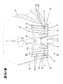
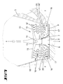
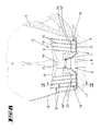
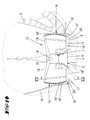
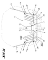
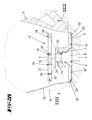
- FIGS. 1 to 6 illustrated first embodiment of a mixing insert 13 is designed both for whipping cream and / or egg whites as well as for frothing milk, wherein the milk is preferably heated at the same time on the integrated in the bottom of the pot 9, the milk when frothing milk.
- the mixing insert 13 of the first embodiment is provided with differently shaped and aligned mixing elements 16.
- first support arms 17 are formed in a diametrical opposite position, which are guided at a small distance to the drive shaft portion 15 radially outward and at a small distance to the pot bottom 9.
- the pot bottom 9 associated with free sections
- the support arms 17 extend in a direction parallel to the pot bottom 9 parallel plane, wherein the vertical distance to the pot bottom 9 is approximately adapted to the viewed in the vertical direction material thickness of the support arms 17, so in the illustrated embodiment about 2mm to 4mm. Further, the support arms 17 extend in the radial direction while leaving a radial distance to the stirring cup wall 18, which radial distance corresponds approximately to two times the vertical distance between the support arms 17 and pot bottom 9.
- each rod-shaped mixing elements 16 'roots so on in the illustrated embodiment, each support arm 17 four such mixing elements 16'.
- the latter are aligned parallel to one another, leaving the same distances considered in the radial direction.
- the rod-shaped mixing elements 16 ' are aligned with the inclusion of an acute angle of about 10 ° to a paraxial, here further towards an axis parallel inclined towards the Haihropfwandung 18, resulting in a diverging course of the mixing elements 16 according to the diametrically opposed arrangement of mixing elements 16 'with respect to the axis of rotation results.
- the mixing elements 16 are tensioned according to this arrangement between the support arms 19 and the foot-side support arms 17, shape accordingly a upon rotation of the mixing insert 13, the fluid to be processed passing gate.
- the free extension length of the rod-shaped mixing elements 16 'between the support arms 17 and the support arms 19 corresponds approximately to the radius of a support arm 17, starting from the agitator axis x to the free end of the support arm 17. Further, the free length of the mixing elements 16' is chosen so in that the support arms 19, which receive their free ends, extend above the fluid to be processed.
- the support arms 19 can also be omitted.
- the radially outermost, rod-shaped mixing element 16 ' is positioned at a radial distance of 10 mm to 12 mm to the stirring pot wall 18.
- the mixing elements 16 ', proceeding radially inwards, are arranged at a uniform distance of about 10 mm from each other.
- each blade element 20 is further over, for example, with a mixing insert 13 produced overall preferably by the plastic injection method a film hinge in the foot-side region of the mixing elements 16 'connected thereto.
- the blade elements 20 can be folded from a first position into a second position and back, so on, in particular, from a vertical position into a horizontal position or from a horizontal position into a vertical position.
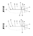
- each blade element 20 As shown in FIGS Figures 3 and 5 a large loading surface, which is defined by the Radialerstreckungswin and the vertical height of the blade element 20. In the horizontal folding position, however, the loading surface is substantially reduced compared to the vertical position, is defined here by the radial length of the blade element 20 and the material thickness thereof in the illustrated embodiment corresponds approximately to the material thickness of a support arm 17.
- the described mixing insert 13 is suitable both for whipping cream or egg whites and for frothing milk.
- the blade elements 20 of the mixing insert 13 In the vertically oriented folding position of the blade elements 20 of the mixing insert 13 is used in particular for whipping cream or protein.
- the rod-shaped mixing elements 16 In this case support the impact process, wherein the cream is held in the web, so that they do not against the Hinhropfwandung 18 or beyond in the direction of vertically above against the lid 12 injected.
- the mixing insert 13 is preferably used for frothing milk.
- the blade elements 20 in this case provide a relatively small loading surface, so that the bubbles of milk, which is foamed by the rod-shaped mixing elements 16 ', are not destroyed. Furthermore, a displacement of the milk is counteracted over a too large loading surface of the blade elements 20 radially outward.
- the conversion of the blade elements 20 and the mixing elements 16 ' can be carried out by the user, this further using optionally provided locking positions of the blade elements 20.
- Preferred and shown is a direction of rotation-dependent conversion of the blade elements 20, this according to a cooperation with the located in the mixing bowl Mass M.
- the mixing insert 13 is rotated in the direction of rotation a FIG. 3 operated, wherein located in the mixing bowl 5 mass M (cream or egg white) pushes the blade elements 20 in the vertical orientation and holds there, wherein further the blade elements 20 are supported back against the performed up to the support arms 17 rod-shaped mixing elements 16 '.
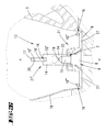
- the mixing insert is operated in the opposite direction of rotation b (cf. FIGS. 4 and 6 ).
- the mass M to be foamed on the side of the blade elements 20 opposite the impact side they automatically become about their hinge axes y in the horizontal orientation or at least approximately into one horizontal orientation pivots, which, along with the impact area significantly reduced.
- the milk to be frothed is in this case stirred, mixed and foamed in the same way, while further counteracting burning of the milk on the heated pan bottom 9.
- rectilinear mixing elements 16 ' these can also be used according to the embodiment in FIG. 7 In the extension direction, it should be wavy.
- rod-shaped mixing elements 16 ' instead of the individual, rod-shaped mixing elements 16 'a fine wire mesh or the like may be provided, this with a preferred mesh size of 1mm to 4mm.
- FIGS. 8 and 9 are rod-shaped mixing elements 16 'in addition to the considered in the radial direction juxtaposition in the direction of rotation also arranged one behind the other, so on with reference to a side view according to FIG. 8 congruent one behind the other.
- This is achieved in the illustrated embodiment by a bow-like design of the mixing elements 16 ', the ironing plane E is in cross-section at an obtuse angle to the vertically aligned blade element plane, further in the illustrated embodiment, approximately at an angle of 80 °, the ironing plane E starting is supported by the support arms supporting the bracket 17 outwardly in the direction of the Hinhropfwandung 18.
- the mixing element brackets 22 are formed for example from a bent, plastic-coated wire or alternatively from a wire-shaped plastic injection molded part, this with an elongated rectangular floor plan (see. FIG. 9 ).
- the approximately vertically aligned, rod-shaped mixing elements 16 'connecting cross sections 23 in this case have a length which corresponds approximately to 0.25 times the extension length of a mixing element 16'.
- the determination of the mixing element bracket 22 is achieved in the region of the transverse sections 23, which pass through the respective support arm 17 and the respective support arm 19 or are integrally formed thereon.
- an offset arrangement of the same on a gap is also possible such that with reference to a side view according to FIG. 8 between two mixing elements 16 'in a viewed in the direction of rotation front mixing element level a mixing element 16' is arranged in the direction of rotation rear mixing element plane.
- FIGS. 10 to 15 show three further embodiments of a mixing insert 13, in which between each of the free ends of the support arms 17 and the support arms 19, a rod-shaped mixing element 16 'is stretched, which further conveys with respect to the agitator axis x convex radially outward in the direction of the Rühropfwandung 18, this while maintaining a radial distance to Rillonitdung 18.
- These wire-shaped mixing elements 16 'strike in particular the pushed through the circulation in the stirring bowl 5 to the Rühropfwandung 18, whipped cream or egg white back into the beating cycle. Also, the through the central arrangement the Rühropfwandung 18 crowded, frothing milk further foamed by the mixing elements 16 '.
- the wire-shaped mixing element 16 ' is as shown in FIG. 11 designed as a closed bracket forms accordingly a mixing elements bracket 22, wherein the thus formed in each case two mixing elements 16 'of a bracket 22 are arranged in a common turning circle.
- the blade element 20 or mixing element 16 "fixed to the support arm 19 also extends in this embodiment.
- the mixing insert 13 of the embodiment according to the Figures 12 and 13 affects the direction of rotation.
- a predetermined direction of rotation a, whipped cream or protein is beaten over the blade elements 20 which initially act on the fluid in the direction of rotation.
- the mixing elements 16 "'arranged downstream in the direction of rotation are less effective here Milk is taken in the opposite direction of rotation, so that in this case first mixes the spring-type mixing elements 16 "'due to the fine structuring air under the milk to be frothed.
- the embodiments according to the Figures 14 and 15 is based on the described embodiment according to the Figures 10 and 11
- the front bracket sections 24 form rod-shaped mixing elements 16 "
- the rear bracket sections 25 form wave-shaped mixing elements 16" in the manner of helical wires.
- This embodiment of the mixing insert 13 also acts in a direction dependent on the direction of rotation, with the bar-shaped or wire-shaped mixing element 16 "initially acting on the fluid, which the wave-shaped mixing element 16" follows in order to whip cream or egg whites in the direction of rotation.
- the direction of rotation is changed so that air is mixed into the milk to be frothed via the wave-shaped mixing elements 16 ".
- FIGS. 16 and 17 show the Figures 16 and 17 an embodiment in which the plug-holder portion 14 only the pot bottom 9 facing support arms 17 has. These are on the upper side, ie facing away from the bottom of the pot 9, with helical mixing elements 16 '' extending in the horizontal plane and radially, forming blade elements 20 for whipping cream or egg whites together with the support arms 17 which are made stronger in the vertical direction than the previously described embodiments . Further, this training is also suitable regardless of the direction of rotation for frothing milk.
- the blade elements 20 are further associated with a horizontally extending mixing element 16 "which extends in a circular section shape with a small vertical distance immediately above the bottom of the pan 9.
- the mixing element 16" is semi-circular, with one on the agitator axis x, wherein the ends of the thus bent in the horizontal plane mixing element 16 "" in the region of the free ends of the blade elements 20 and the support arms 17 are supported.
- the mixing element 16 "" is formed in the illustrated embodiment in the longitudinal extension of the same helical, this while enforcing a the course of the mixing element 16 "" following stabilization wire 26th
- the mixing element 16 "" is arranged at least in partial horizontal coverage to the blade elements 20 and support arms 17, wherein in the illustrated embodiment, the coverage area corresponds approximately to 0.6 to 0.7 times the Mischetti barnmessers.
- the spring-like mixing element 16 "" rotates with a small vertical distance to the bottom of the pot 9, further with a small radial distance to the stirring pot wall 18, at which bottom or wall milk, cream or protein can collect through the rotational forces.
- the whipped cream or protein as well as the milk to be frothed spreads vertically upwards, whereby only the not yet processed liquid is beaten or foamed by the mixing insert 13.
- the mixing element 16 "" may also be in the form of a full circle, or alternatively also in the form of two quarter circles spaced apart in the direction of rotation.
- FIGS. 18 to 20 show a mixing insert 13 in another embodiment. This is particularly suitable for frothing milk, in particular for frothing milk in amounts of 50ml to 400ml.
- each other mixing arms 27, 28 are provided on the central plug holder portion 14. These extend in the radial direction to the Rühropfwandung 18, leaving a small radial distance.
- the two mixing arms 27 extend radially opposite as well as the mixing arms 28, which in a plan according to FIG. 20 viewed at right angles to the mixing arms 27 are arranged.
- the mixing arms 27 extend equal to the support arms 17 of the embodiments described above with a small vertical distance plane parallel to the pot bottom 9, while the mixing arms 28 are arranged in a vertically offset thereto horizontal plane.
- the vertical offset of the mixing arms 27, 28 to each other in the illustrated embodiment is several millimeters, for example 10mm.
- Each mixing arm 27, 28 is provided with a mixing element 16 "'oriented transversely to its extent and thus almost in the direction of rotation, which is aligned in a horizontal plane and helical shaped in the illustrated embodiment in the manner of a cylindrical spring the free ends of the mixing arms 27, 28 fixed to the upper side, wherein further considered in the vertical direction lower Mixing arms 27 each have a mixing element 16 "', while the vertically upper mixing arms 28 each carry two provided in radial juxtaposition mixing elements 16"' wear.
- the distance between the turns of the mixing elements 16 "'approximately defines the bubble size in the medium to be foamed.
- a winding spacing of 1 mm to 4 mm is provided in a preferred embodiment.
- the above-described mixing insert 13 is particularly suitable for foaming milk, but also finds, in particular, by the, in the direction of rotation facing loading surfaces forming mixing arms 27, 28 application for whipping cream and / or protein.
- the mixing elements 16 "' may also be arranged obliquely to a horizontal plane instead of the strictly horizontal orientation, for example at an angle of up to 30 ° to the horizontal or vertical plane.
- the sprung or helical mixing elements 16 "'of the above-described embodiments may be made of metal or plastic, further cylindrical, conical or variable in diameter .
- a grid may be added to a cylindrical shape, wherein at Rotation of the mixing insert 13 the milk is pressed through the grid and foamed.
- FIGS 21 and 22 show a further development of the above-described embodiment, in which case the mixing arms each have a mixing element 16 '' in helical shape associated therewith, in each case two and the upper mixing arms 28. Further, radially inward to the mixing elements 16 '' the vertically upper mixing arms 28 rod-shaped mixing elements 16 'set which are arranged diverging upwards like the first embodiment, this in each case parallel alignment of mixing elements 16' of each mixing arm 28. These mixing elements 16 'run starting from the mixing arms 28 are free, are designed accordingly stable.
- the mixing elements 16 ' are rooted in an essentially U-shaped foot 29, which is adapted to the cross-section of the mixing arm 28, for plug-in connection of a mixing element section combined in this way to the respective mixing arm 28.
- the mixing element sections can also be clamped or screwed to the mixing arms 28.
- FIG. 23 and 24 Another embodiment show the Figures 23 and 24 , wherein here also cross-shaped mixing arms 27, 28 are provided. These mixing arms 27, 28, which are arranged in opposing pairs, are arranged in vertically different horizontal planes and, in accordance with the above-described embodiment, carry mixing elements 16 "aligned transversely to the extension of the mixing arms 27, 28. These are designed elongate plate-shaped and provided with bores 30.
- the change of the loading surface is also here according to the embodiments of the first embodiment, according to a cooperation with the in the stirring cup 5 mass M automatically depending on the direction of rotation.
- FIGS. 25 to 27 Another favorable embodiment of a mixing insert 13 both for whipping cream or protein as well as for frothing milk show the FIGS. 25 to 27 .
- Each mixing insert part 31, 31 ' has a plug-on section 32, 32', each forming a plug-holder section 14. These are in a projection considered aligned with each other on the bottom of the pot 9 and arranged symmetrically with respect to a horizontal mirror plane.
- the Stirring 9 can be assigned, so for frothing milk, the mixing insert 31 and whipping cream or Egg white the mixing insert 31 '.
- the support arms 19 of the mixing insert part 31 'so vertically spaced from the mixing elements 16''of the opposite mixing insert part 31, that this in the foaming of milk in the in FIG. 25 shown assignment position of the mixing insert 13 rotate at a distance above the milk level in the mixing pot 5 and thus does not affect the formation of bubbles in the milk foam.
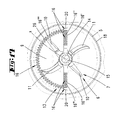
- the mixing elements 16 are formed as, the plate members 33 distancing, vertical webs 34 and extend in a radial direction spiral (see. FIG. 29 ).
- the lower plate member 33 While the upper plate member 33 is fully closed, forming a disc, the lower plate member 33 has a central inlet opening 35. This surrounds the agitator 6 and the inside of the upper plate part 33 outgoing, the inlet opening 35 passing through plug holder portion 14, leaving a free, annular inlet cross-section.
- the lower plate member 33 is funnel-shaped downwardly formed in the central region, so that the free vertical distance between the plate members 33 in the central region is greater than in the edge region.
- the webs 34 forming the mixing elements 16 also have a height which increases toward the central region of the mixing insert 13.
- the mixing insert 13 thus designed in the form of an impeller is selected to be of diameter such that a radial distance of, for example, 15 mm to the stirring pot wall 18 remains.
- the mixing insert 13 is further arranged in the operating position so that it rests on the mirror of the fluid to be processed or is aligned with a small vertical distance on this mirror.
- the air is pressed by the rotation of the mixing insert 13 radially outward against the Haihropfwandung 18, whereby the fluid, such as the milk is foamed.
- the air is pressed into the fluid, creating a fine milk foam.
- a whipping of cream is possible, which is likewise permeated with air accordingly.
- the plug-in support portion 14 is axially elongated, passes through the ceiling-side plate member 30 and projects freely into the interior of the stirring pot 5.
- End of the so-shaped guide portion 36 is provided with a diameter enlarged stop collar 37.
- the cross section of the guide section 36, as well as the interspersed opening in the mixing part-side cover non-circular, here rectangular, whereby the mixing element 14 is secured against rotation, but along the guide portion 36 is displaced. With the volume expansion of the fluid, the entire mixing insert 13 moves vertically upwards, the air being sucked from below through the inlet opening 35 from the mixing pot 5.
Landscapes
- Chemical & Material Sciences (AREA)
- Chemical Kinetics & Catalysis (AREA)
- Engineering & Computer Science (AREA)
- Food Science & Technology (AREA)
- Mechanical Engineering (AREA)
- Food-Manufacturing Devices (AREA)
- Dairy Products (AREA)
Priority Applications (8)
| Application Number | Priority Date | Filing Date | Title |
|---|---|---|---|
| EP12150022A EP2441363A1 (fr) | 2009-03-06 | 2010-03-01 | Insert de mélange pour un pot |
| PL12150023T PL2441364T3 (pl) | 2009-03-06 | 2010-03-01 | Zespół mieszający |
| EP12150021A EP2438839A1 (fr) | 2009-03-06 | 2010-03-01 | Insert de mélange en mousse et appareil de cuisson fonctionnant de manière électromotorisée et doté d'un tel insert |
| EP12150025A EP2438840A1 (fr) | 2009-03-06 | 2010-03-01 | Insert de mélange pour un pot |
| EP12150019.3A EP2441362B1 (fr) | 2009-03-06 | 2010-03-01 | Insert de mélange pour un pot |
| PL10155055T PL2225981T3 (pl) | 2009-03-06 | 2010-03-01 | Wkład mieszający do naczynia mieszającego |
| PL12150019T PL2441362T3 (pl) | 2009-03-06 | 2010-03-01 | Wkład mieszający do naczynia mieszającego |
| EP12150023.5A EP2441364B1 (fr) | 2009-03-06 | 2010-03-01 | Insert de mélange pour un pot |
Applications Claiming Priority (1)
| Application Number | Priority Date | Filing Date | Title |
|---|---|---|---|
| DE102009003576A DE102009003576A1 (de) | 2009-03-06 | 2009-03-06 | Mischeinsatz für einen Rührtopf |
Related Child Applications (6)
| Application Number | Title | Priority Date | Filing Date |
|---|---|---|---|
| EP12150021A Division-Into EP2438839A1 (fr) | 2009-03-06 | 2010-03-01 | Insert de mélange en mousse et appareil de cuisson fonctionnant de manière électromotorisée et doté d'un tel insert |
| EP12150022A Division-Into EP2441363A1 (fr) | 2009-03-06 | 2010-03-01 | Insert de mélange pour un pot |
| EP12150023.5A Division-Into EP2441364B1 (fr) | 2009-03-06 | 2010-03-01 | Insert de mélange pour un pot |
| EP12150019.3A Division-Into EP2441362B1 (fr) | 2009-03-06 | 2010-03-01 | Insert de mélange pour un pot |
| EP12150019.3A Division EP2441362B1 (fr) | 2009-03-06 | 2010-03-01 | Insert de mélange pour un pot |
| EP12150025A Division-Into EP2438840A1 (fr) | 2009-03-06 | 2010-03-01 | Insert de mélange pour un pot |
Publications (3)
| Publication Number | Publication Date |
|---|---|
| EP2225981A2 true EP2225981A2 (fr) | 2010-09-08 |
| EP2225981A3 EP2225981A3 (fr) | 2011-03-23 |
| EP2225981B1 EP2225981B1 (fr) | 2014-04-30 |
Family
ID=42261884
Family Applications (6)
| Application Number | Title | Priority Date | Filing Date |
|---|---|---|---|
| EP12150025A Withdrawn EP2438840A1 (fr) | 2009-03-06 | 2010-03-01 | Insert de mélange pour un pot |
| EP12150022A Withdrawn EP2441363A1 (fr) | 2009-03-06 | 2010-03-01 | Insert de mélange pour un pot |
| EP10155055.6A Active EP2225981B1 (fr) | 2009-03-06 | 2010-03-01 | Insert de mixage pour un bol de mélange |
| EP12150023.5A Not-in-force EP2441364B1 (fr) | 2009-03-06 | 2010-03-01 | Insert de mélange pour un pot |
| EP12150019.3A Not-in-force EP2441362B1 (fr) | 2009-03-06 | 2010-03-01 | Insert de mélange pour un pot |
| EP12150021A Withdrawn EP2438839A1 (fr) | 2009-03-06 | 2010-03-01 | Insert de mélange en mousse et appareil de cuisson fonctionnant de manière électromotorisée et doté d'un tel insert |
Family Applications Before (2)
| Application Number | Title | Priority Date | Filing Date |
|---|---|---|---|
| EP12150025A Withdrawn EP2438840A1 (fr) | 2009-03-06 | 2010-03-01 | Insert de mélange pour un pot |
| EP12150022A Withdrawn EP2441363A1 (fr) | 2009-03-06 | 2010-03-01 | Insert de mélange pour un pot |
Family Applications After (3)
| Application Number | Title | Priority Date | Filing Date |
|---|---|---|---|
| EP12150023.5A Not-in-force EP2441364B1 (fr) | 2009-03-06 | 2010-03-01 | Insert de mélange pour un pot |
| EP12150019.3A Not-in-force EP2441362B1 (fr) | 2009-03-06 | 2010-03-01 | Insert de mélange pour un pot |
| EP12150021A Withdrawn EP2438839A1 (fr) | 2009-03-06 | 2010-03-01 | Insert de mélange en mousse et appareil de cuisson fonctionnant de manière électromotorisée et doté d'un tel insert |
Country Status (6)
| Country | Link |
|---|---|
| EP (6) | EP2438840A1 (fr) |
| CN (6) | CN101889827A (fr) |
| DE (1) | DE102009003576A1 (fr) |
| ES (3) | ES2464092T3 (fr) |
| PL (3) | PL2225981T3 (fr) |
| PT (3) | PT2441364E (fr) |
Cited By (11)
| Publication number | Priority date | Publication date | Assignee | Title |
|---|---|---|---|---|
| EP2636344A1 (fr) * | 2012-03-09 | 2013-09-11 | Whirlpool Corporation | Robot de cuisine et ensemble de coupe réglable |
| WO2015019095A1 (fr) * | 2013-08-06 | 2015-02-12 | Kenwood Limited | Équipement de préparation d'aliments |
| GB2522899A (en) * | 2014-02-10 | 2015-08-12 | Kenwood Ltd | Food blender |
| CN105996821A (zh) * | 2016-07-12 | 2016-10-12 | 广东小熊电器有限公司 | 一种家用粉碎机 |
| WO2016177630A1 (fr) * | 2015-05-06 | 2016-11-10 | Nestec S.A. | Élément d'agitation déployable |
| EP3335604A1 (fr) * | 2016-12-19 | 2018-06-20 | BSH Hausgeräte GmbH | Accessoire de mélange pour bac de mélange |
| JP2021049234A (ja) * | 2019-09-26 | 2021-04-01 | 株式会社愛工舎製作所 | 食材用ミキサーの回転刃構造 |
| CN114681979A (zh) * | 2020-12-31 | 2022-07-01 | 太湖金张科技股份有限公司 | 一种供胶过滤装置 |
| EP4257018A1 (fr) * | 2022-03-24 | 2023-10-11 | Keller und Koop GmbH | Boîtier de protection pour un outil de cuisine rotatif |
| CN116920682A (zh) * | 2023-09-13 | 2023-10-24 | 泉州市创达机械制造有限公司 | 一种湿巾生产用搅拌装置及其生产工艺 |
| US12383101B2 (en) | 2019-05-28 | 2025-08-12 | Sharkninja Operating Llc | Heated food processor |
Families Citing this family (16)
| Publication number | Priority date | Publication date | Assignee | Title |
|---|---|---|---|---|
| CN102173002B (zh) * | 2010-12-30 | 2013-04-24 | 临安市绿源精细化学品有限公司 | 一种旋爪式密炼机 |
| CN103584751A (zh) * | 2012-08-17 | 2014-02-19 | 李文庆 | 一种打蛋器的改良机构 |
| CN103330489A (zh) * | 2013-06-08 | 2013-10-02 | 广东顺德高达科菲电器制造有限公司 | 一种底部驱动式奶泡机 |
| DE102014217241A1 (de) * | 2014-08-28 | 2016-03-03 | BSH Hausgeräte GmbH | Messeranordnung für ein Küchengerät sowie Küchengerät mit einer Messeranordnung |
| CN106108715B (zh) | 2016-08-23 | 2019-06-14 | 宁波市普力升工贸有限公司 | 搅拌器及应用该搅拌器的打蛋器 |
| CN108245044B (zh) * | 2016-12-29 | 2023-07-14 | 浙江绍兴苏泊尔生活电器有限公司 | 搅拌棒组件及具有其的料理机 |
| CN107692882A (zh) * | 2017-11-14 | 2018-02-16 | 叶雨玲 | 带延展结构的面包机搅拌装置 |
| CN107802191A (zh) * | 2017-11-14 | 2018-03-16 | 叶雨玲 | 多用途面包机搅拌装置 |
| CN107890303A (zh) * | 2017-11-14 | 2018-04-10 | 叶雨玲 | 多用面包机搅拌装置 |
| CN111655049B (zh) * | 2018-02-20 | 2023-10-27 | 雀巢产品有限公司 | 食物加工系统及相关联的方法 |
| CN110522326B (zh) * | 2019-10-19 | 2022-04-29 | 湖南五月豆香食品有限公司 | 一种研磨精细的豆浆机 |
| CN114073405A (zh) * | 2020-08-19 | 2022-02-22 | 拓浦精工智能制造(邵阳)有限公司 | 旋片式破泡器及烹饪器具 |
| CN112263928A (zh) * | 2020-09-24 | 2021-01-26 | 安徽唯宝印刷科技有限公司 | 一种润版液加工设备 |
| CN112495233B (zh) * | 2020-11-12 | 2023-02-24 | 株洲精工硬质合金有限公司 | 一种机电一体化搅拌装置 |
| DE202022105005U1 (de) | 2022-09-06 | 2022-09-14 | Wundermix Gmbh | Rührvorrichtung für eine Küchenmaschine |
| DE202024002691U1 (de) * | 2023-12-29 | 2026-01-23 | Wundermix Gmbh | Multifunktionsküchenmaschine |
Citations (4)
| Publication number | Priority date | Publication date | Assignee | Title |
|---|---|---|---|---|
| US4312596A (en) | 1978-05-24 | 1982-01-26 | Tokyo Electric Limited | Beating blade member of beater |
| EP0645178A1 (fr) | 1993-09-24 | 1995-03-29 | GIANT S.r.l. | Dispositif pour le traitement des denrées alimentaires liquides ou pasteux |
| DE29604547U1 (de) | 1996-03-13 | 1996-05-30 | Vorwerk & Co Interholding Gmbh, 42275 Wuppertal | Mischaufsatz für den Messereinsatz eines Haushaltsmixgerätes |
| EP0757531B1 (fr) | 1994-04-28 | 1998-06-10 | Vorwerk & Co. Interholding GmbH | Robot menager comportant un bac a agitation et un mecanisme d'entrainement de l'agitateur du bac |
Family Cites Families (23)
| Publication number | Priority date | Publication date | Assignee | Title |
|---|---|---|---|---|
| US2191739A (en) * | 1937-10-23 | 1940-02-27 | American Cyanamid Co | Agitating, aerating, and/or mixing machine |
| FR1159265A (fr) * | 1956-09-19 | 1958-06-25 | Mélangeur à turbine | |
| FR1474582A (fr) * | 1966-04-05 | 1967-03-24 | Agitateur mélangeur pour appareils utilisés pour le flottage à mousse | |
| DE6908643U (de) * | 1969-03-03 | 1969-07-17 | Emil Wittern | Stabixer mit frischluftbelueftung unterhalb der fluessigkeitsoberflaeche |
| US3690621A (en) * | 1969-03-04 | 1972-09-12 | Itsuko Tanaka | Agitator |
| US3692427A (en) * | 1970-07-13 | 1972-09-19 | Colortex Sa | High speed mixing impeller |
| US3811211A (en) * | 1971-06-03 | 1974-05-21 | Amerace Esna Corp | Bowling ball indicia display means and method of assemblying same |
| US4454078A (en) * | 1980-11-10 | 1984-06-12 | General Signal Corporation | Mixing systems having agitators for mixing gas with liquid |
| DE3507276C2 (de) * | 1985-03-01 | 1987-01-08 | Vorwerk & Co Interholding Gmbh, 5600 Wuppertal | Elektromotorisch betriebenes Haushaltsmixgerät |
| DE3545420C1 (en) * | 1985-12-20 | 1987-03-26 | Bosch Siemens Hausgeraete | Comminuting and stirring device for foodstuffs |
| US5516208A (en) * | 1995-03-27 | 1996-05-14 | Givant; Madeline F. | Adjustable pot stirrer |
| DE19613951A1 (de) * | 1996-04-06 | 1997-10-09 | Braun Ag | Rührwerkzeug für ein Küchengerät zum Rühren und Schlagen von Lebensmitteln |
| DE29612865U1 (de) * | 1996-07-24 | 1996-10-10 | Chen, Tse-Hsiung, Tao-Yuan | Schneidwerkzeug für einen Mixer |
| AU756226B2 (en) * | 1999-02-22 | 2003-01-09 | Breville Pty Ltd | Container for an automatic bread maker |
| DE29911750U1 (de) * | 1999-07-08 | 2000-01-05 | Softgraph GmbH, 10117 Berlin | Absenkbarer Rührer für Brotbackautomaten |
| CN1179650C (zh) * | 2000-06-03 | 2004-12-15 | 布雷维尔有限公司 | 自动面包机 |
| CN2456832Y (zh) * | 2000-12-08 | 2001-10-31 | 王一帆 | 搅拌器 |
| FR2850856B1 (fr) | 2003-02-10 | 2005-07-01 | Realisation Mecaniques Soc Et | Couteau rotatif a deux lames |
| EP1486153A1 (fr) * | 2003-06-10 | 2004-12-15 | Kenwood Marks Limited | Machine de fabrication de pain et arrangement d'un bras mélangeur associé |
| JP2005066946A (ja) * | 2003-08-21 | 2005-03-17 | Ngk Insulators Ltd | 押出機用スクリュー、スクリュー式押出機、及びこれを用いた混練押出装置 |
| US20060032810A1 (en) * | 2004-08-16 | 2006-02-16 | Dudley Theresa M | Tuna spinner |
| EP1656866A1 (fr) * | 2004-11-12 | 2006-05-17 | Nestec S.A. | Appareil et méthode pour la préparation de mousse à partir d'un liquide alimentaire à base de lait |
| CN101500697B (zh) * | 2006-07-13 | 2012-07-18 | 浦瑞玛柯Feg有限责任公司 | 用于混合的搅拌器 |
-
2009
- 2009-03-06 DE DE102009003576A patent/DE102009003576A1/de not_active Withdrawn
-
2010
- 2010-03-01 ES ES12150019.3T patent/ES2464092T3/es active Active
- 2010-03-01 PL PL10155055T patent/PL2225981T3/pl unknown
- 2010-03-01 EP EP12150025A patent/EP2438840A1/fr not_active Withdrawn
- 2010-03-01 EP EP12150022A patent/EP2441363A1/fr not_active Withdrawn
- 2010-03-01 PL PL12150019T patent/PL2441362T3/pl unknown
- 2010-03-01 EP EP10155055.6A patent/EP2225981B1/fr active Active
- 2010-03-01 ES ES12150023T patent/ES2408686T3/es active Active
- 2010-03-01 ES ES10155055.6T patent/ES2465040T3/es active Active
- 2010-03-01 PT PT121500235T patent/PT2441364E/pt unknown
- 2010-03-01 PL PL12150023T patent/PL2441364T3/pl unknown
- 2010-03-01 PT PT121500193T patent/PT2441362E/pt unknown
- 2010-03-01 EP EP12150023.5A patent/EP2441364B1/fr not_active Not-in-force
- 2010-03-01 PT PT101550556T patent/PT2225981E/pt unknown
- 2010-03-01 EP EP12150019.3A patent/EP2441362B1/fr not_active Not-in-force
- 2010-03-01 EP EP12150021A patent/EP2438839A1/fr not_active Withdrawn
- 2010-03-08 CN CN2010102239485A patent/CN101889827A/zh active Pending
- 2010-03-08 CN CN201410043163.8A patent/CN103767574A/zh active Pending
- 2010-03-08 CN CN201410043180.1A patent/CN103735183A/zh active Pending
- 2010-03-08 CN CN201410043177.XA patent/CN103735182A/zh active Pending
- 2010-03-08 CN CN201410043170.8A patent/CN103767575A/zh active Pending
- 2010-03-08 CN CN201410042997.7A patent/CN103767573A/zh active Pending
Patent Citations (4)
| Publication number | Priority date | Publication date | Assignee | Title |
|---|---|---|---|---|
| US4312596A (en) | 1978-05-24 | 1982-01-26 | Tokyo Electric Limited | Beating blade member of beater |
| EP0645178A1 (fr) | 1993-09-24 | 1995-03-29 | GIANT S.r.l. | Dispositif pour le traitement des denrées alimentaires liquides ou pasteux |
| EP0757531B1 (fr) | 1994-04-28 | 1998-06-10 | Vorwerk & Co. Interholding GmbH | Robot menager comportant un bac a agitation et un mecanisme d'entrainement de l'agitateur du bac |
| DE29604547U1 (de) | 1996-03-13 | 1996-05-30 | Vorwerk & Co Interholding Gmbh, 42275 Wuppertal | Mischaufsatz für den Messereinsatz eines Haushaltsmixgerätes |
Cited By (17)
| Publication number | Priority date | Publication date | Assignee | Title |
|---|---|---|---|---|
| US9522399B2 (en) | 2012-03-09 | 2016-12-20 | Whirlpool Corporation | Food processor and adjustable cutting assembly |
| EP2636344A1 (fr) * | 2012-03-09 | 2013-09-11 | Whirlpool Corporation | Robot de cuisine et ensemble de coupe réglable |
| WO2015019095A1 (fr) * | 2013-08-06 | 2015-02-12 | Kenwood Limited | Équipement de préparation d'aliments |
| GB2522899A (en) * | 2014-02-10 | 2015-08-12 | Kenwood Ltd | Food blender |
| GB2522899B (en) * | 2014-02-10 | 2017-11-08 | Kenwood Ltd | Food Blender |
| US11052357B2 (en) | 2015-05-06 | 2021-07-06 | Societe Des Produits Nestie S.A. | Deployable stirring member |
| WO2016177630A1 (fr) * | 2015-05-06 | 2016-11-10 | Nestec S.A. | Élément d'agitation déployable |
| JP2018515166A (ja) * | 2015-05-06 | 2018-06-14 | ネステク ソシエテ アノニム | 展開可能な撹拌部材 |
| CN105996821A (zh) * | 2016-07-12 | 2016-10-12 | 广东小熊电器有限公司 | 一种家用粉碎机 |
| EP3335604A1 (fr) * | 2016-12-19 | 2018-06-20 | BSH Hausgeräte GmbH | Accessoire de mélange pour bac de mélange |
| US12383101B2 (en) | 2019-05-28 | 2025-08-12 | Sharkninja Operating Llc | Heated food processor |
| JP2021049234A (ja) * | 2019-09-26 | 2021-04-01 | 株式会社愛工舎製作所 | 食材用ミキサーの回転刃構造 |
| CN114681979A (zh) * | 2020-12-31 | 2022-07-01 | 太湖金张科技股份有限公司 | 一种供胶过滤装置 |
| CN114681979B (zh) * | 2020-12-31 | 2023-12-29 | 太湖金张科技股份有限公司 | 一种供胶过滤装置 |
| EP4257018A1 (fr) * | 2022-03-24 | 2023-10-11 | Keller und Koop GmbH | Boîtier de protection pour un outil de cuisine rotatif |
| CN116920682A (zh) * | 2023-09-13 | 2023-10-24 | 泉州市创达机械制造有限公司 | 一种湿巾生产用搅拌装置及其生产工艺 |
| CN116920682B (zh) * | 2023-09-13 | 2023-12-05 | 泉州市创达机械制造有限公司 | 一种湿巾生产用搅拌装置及其生产工艺 |
Also Published As
| Publication number | Publication date |
|---|---|
| PL2225981T3 (pl) | 2014-08-29 |
| CN103767575A (zh) | 2014-05-07 |
| ES2408686T3 (es) | 2013-06-21 |
| EP2225981B1 (fr) | 2014-04-30 |
| CN101889827A (zh) | 2010-11-24 |
| EP2225981A3 (fr) | 2011-03-23 |
| ES2464092T3 (es) | 2014-05-30 |
| EP2441364B1 (fr) | 2013-04-17 |
| ES2465040T3 (es) | 2014-06-05 |
| EP2441364A1 (fr) | 2012-04-18 |
| PT2441364E (pt) | 2013-06-04 |
| CN103735183A (zh) | 2014-04-23 |
| PT2225981E (pt) | 2014-06-09 |
| PT2441362E (pt) | 2014-06-09 |
| DE102009003576A1 (de) | 2010-09-09 |
| CN103767574A (zh) | 2014-05-07 |
| EP2438839A1 (fr) | 2012-04-11 |
| PL2441364T3 (pl) | 2013-08-30 |
| EP2441362A1 (fr) | 2012-04-18 |
| EP2438840A1 (fr) | 2012-04-11 |
| EP2441363A1 (fr) | 2012-04-18 |
| CN103735182A (zh) | 2014-04-23 |
| EP2441362B1 (fr) | 2014-04-30 |
| PL2441362T3 (pl) | 2014-08-29 |
| CN103767573A (zh) | 2014-05-07 |
Similar Documents
| Publication | Publication Date | Title |
|---|---|---|
| EP2441362B1 (fr) | Insert de mélange pour un pot | |
| EP1449472B2 (fr) | Dispositif à actionnement manuel pour couper des produits alimentaires | |
| EP1833338B1 (fr) | Dispositif pour produire de la mousse de lait | |
| DE10001455A1 (de) | Vorrichtung zum Zerkleinern von Lebensmitteln | |
| DE10050719A1 (de) | Vorrichtung zur Erzeugung von Milchschaum für ein Kaffeegetränk, insbesondere für Capuccino-Kaffee | |
| EP3185732B1 (fr) | Ensemble couteau pour un appareil de cuisine et appareil de cuisine équipé d'un ensemble couteau | |
| DE102007056711A1 (de) | Knet- und Rührwerkzeug und Küchenmaschine | |
| EP1639928A1 (fr) | Ensemble de lames pour un robot ménager a commande électromotrice et robot ménager correspondant | |
| EP2326226B1 (fr) | Agitateur pour appareil ménager | |
| EP0570677A1 (fr) | Outil broyeur-mélangeur d'un robot de cuisine | |
| DE102012107520A1 (de) | Drehantreibbarer Messersatz | |
| DE102008026129B4 (de) | Küchenmaschine zur Herstellung strangförmiger Teigwaren, insbesondere von Nudeln | |
| EP0842627B1 (fr) | Outil à mélanger, pétrir ou couper pour un appareil de cuisine | |
| DE3438766A1 (de) | Vorrichtung zur erzeugung einer wirbelbewegung in einer fluessigen oder pastoesen masse | |
| DE19613951A1 (de) | Rührwerkzeug für ein Küchengerät zum Rühren und Schlagen von Lebensmitteln | |
| DE10031753A1 (de) | Arbeitsbehälter zum Aufnehmen und Bearbeiten von Nahrungsmitteln | |
| DE202021002124U1 (de) | Erweiterungs-Einsatz zur Aufnahme in einem Zubereitungsgefäß einer Küchenmaschine sowie Küchenmaschine mit dem Erweiterungs-Einsatz | |
| DE102020001219A1 (de) | Kaffeeschaumgerät bzw. Kaffeekochgerät mit Kaffeeschaumeinsatz | |
| EP3492164A1 (fr) | Couteau mélangeur | |
| DE102016110825A1 (de) | Elektromotorisch betriebene Küchenmaschine | |
| DE102022106265A1 (de) | Erweiterungs-Einsatz | |
| EP0795289A1 (fr) | Elément de connexion pour faire de la crème fouettée | |
| EP3282907B1 (fr) | Dispositif de réglage de passage à palier axial pour dispositif de broyage de produit alimentaire et dispositif de broyage de produit alimentaire équipé d'un dispositif de réglage de passage | |
| DE3843703A1 (de) | Kuechenmaschine zum kneten, ruehren und schneiden | |
| EP4119019A1 (fr) | Dispositif de coupe pour un broyage des denrées alimentaires et appareil de préparation des aliments |
Legal Events
| Date | Code | Title | Description |
|---|---|---|---|
| PUAI | Public reference made under article 153(3) epc to a published international application that has entered the european phase |
Free format text: ORIGINAL CODE: 0009012 |
|
| AK | Designated contracting states |
Kind code of ref document: A2 Designated state(s): AT BE BG CH CY CZ DE DK EE ES FI FR GB GR HR HU IE IS IT LI LT LU LV MC MK MT NL NO PL PT RO SE SI SK SM TR |
|
| AX | Request for extension of the european patent |
Extension state: AL BA ME RS |
|
| PUAL | Search report despatched |
Free format text: ORIGINAL CODE: 0009013 |
|
| AK | Designated contracting states |
Kind code of ref document: A3 Designated state(s): AT BE BG CH CY CZ DE DK EE ES FI FR GB GR HR HU IE IS IT LI LT LU LV MC MK MT NL NO PL PT RO SE SI SK SM TR |
|
| AX | Request for extension of the european patent |
Extension state: AL BA ME RS |
|
| 17P | Request for examination filed |
Effective date: 20110704 |
|
| 17Q | First examination report despatched |
Effective date: 20120201 |
|
| GRAP | Despatch of communication of intention to grant a patent |
Free format text: ORIGINAL CODE: EPIDOSNIGR1 |
|
| INTG | Intention to grant announced |
Effective date: 20131119 |
|
| GRAS | Grant fee paid |
Free format text: ORIGINAL CODE: EPIDOSNIGR3 |
|
| GRAA | (expected) grant |
Free format text: ORIGINAL CODE: 0009210 |
|
| RIN1 | Information on inventor provided before grant (corrected) |
Inventor name: SCHOMACHER, JUTTA Inventor name: LISS, RAPHAEL Inventor name: CASTILLO, THALIA GARCIA Inventor name: MAHMUDOV, TURSUN |
|
| AK | Designated contracting states |
Kind code of ref document: B1 Designated state(s): AT BE BG CH CY CZ DE DK EE ES FI FR GB GR HR HU IE IS IT LI LT LU LV MC MK MT NL NO PL PT RO SE SI SK SM TR |
|
| REG | Reference to a national code |
Ref country code: CH Ref legal event code: EP Ref country code: GB Ref legal event code: FG4D Free format text: NOT ENGLISH |
|
| REG | Reference to a national code |
Ref country code: AT Ref legal event code: REF Ref document number: 664538 Country of ref document: AT Kind code of ref document: T Effective date: 20140515 |
|
| REG | Reference to a national code |
Ref country code: IE Ref legal event code: FG4D Free format text: LANGUAGE OF EP DOCUMENT: GERMAN |
|
| REG | Reference to a national code |
Ref country code: ES Ref legal event code: FG2A Ref document number: 2465040 Country of ref document: ES Kind code of ref document: T3 Effective date: 20140605 |
|
| REG | Reference to a national code |
Ref country code: PT Ref legal event code: SC4A Free format text: AVAILABILITY OF NATIONAL TRANSLATION Effective date: 20140529 |
|
| REG | Reference to a national code |
Ref country code: DE Ref legal event code: R096 Ref document number: 502010006779 Country of ref document: DE Effective date: 20140618 |
|
| REG | Reference to a national code |
Ref country code: PL Ref legal event code: T3 |
|
| REG | Reference to a national code |
Ref country code: LT Ref legal event code: MG4D |
|
| REG | Reference to a national code |
Ref country code: NL Ref legal event code: VDEP Effective date: 20140430 |
|
| PG25 | Lapsed in a contracting state [announced via postgrant information from national office to epo] |
Ref country code: IS Free format text: LAPSE BECAUSE OF FAILURE TO SUBMIT A TRANSLATION OF THE DESCRIPTION OR TO PAY THE FEE WITHIN THE PRESCRIBED TIME-LIMIT Effective date: 20140830 Ref country code: BG Free format text: LAPSE BECAUSE OF FAILURE TO SUBMIT A TRANSLATION OF THE DESCRIPTION OR TO PAY THE FEE WITHIN THE PRESCRIBED TIME-LIMIT Effective date: 20140730 Ref country code: LT Free format text: LAPSE BECAUSE OF FAILURE TO SUBMIT A TRANSLATION OF THE DESCRIPTION OR TO PAY THE FEE WITHIN THE PRESCRIBED TIME-LIMIT Effective date: 20140430 Ref country code: GR Free format text: LAPSE BECAUSE OF FAILURE TO SUBMIT A TRANSLATION OF THE DESCRIPTION OR TO PAY THE FEE WITHIN THE PRESCRIBED TIME-LIMIT Effective date: 20140731 Ref country code: FI Free format text: LAPSE BECAUSE OF FAILURE TO SUBMIT A TRANSLATION OF THE DESCRIPTION OR TO PAY THE FEE WITHIN THE PRESCRIBED TIME-LIMIT Effective date: 20140430 Ref country code: NL Free format text: LAPSE BECAUSE OF FAILURE TO SUBMIT A TRANSLATION OF THE DESCRIPTION OR TO PAY THE FEE WITHIN THE PRESCRIBED TIME-LIMIT Effective date: 20140430 Ref country code: CY Free format text: LAPSE BECAUSE OF FAILURE TO SUBMIT A TRANSLATION OF THE DESCRIPTION OR TO PAY THE FEE WITHIN THE PRESCRIBED TIME-LIMIT Effective date: 20140430 Ref country code: NO Free format text: LAPSE BECAUSE OF FAILURE TO SUBMIT A TRANSLATION OF THE DESCRIPTION OR TO PAY THE FEE WITHIN THE PRESCRIBED TIME-LIMIT Effective date: 20140730 |
|
| PG25 | Lapsed in a contracting state [announced via postgrant information from national office to epo] |
Ref country code: LV Free format text: LAPSE BECAUSE OF FAILURE TO SUBMIT A TRANSLATION OF THE DESCRIPTION OR TO PAY THE FEE WITHIN THE PRESCRIBED TIME-LIMIT Effective date: 20140430 Ref country code: HR Free format text: LAPSE BECAUSE OF FAILURE TO SUBMIT A TRANSLATION OF THE DESCRIPTION OR TO PAY THE FEE WITHIN THE PRESCRIBED TIME-LIMIT Effective date: 20140430 Ref country code: SE Free format text: LAPSE BECAUSE OF FAILURE TO SUBMIT A TRANSLATION OF THE DESCRIPTION OR TO PAY THE FEE WITHIN THE PRESCRIBED TIME-LIMIT Effective date: 20140430 |
|
| PG25 | Lapsed in a contracting state [announced via postgrant information from national office to epo] |
Ref country code: DK Free format text: LAPSE BECAUSE OF FAILURE TO SUBMIT A TRANSLATION OF THE DESCRIPTION OR TO PAY THE FEE WITHIN THE PRESCRIBED TIME-LIMIT Effective date: 20140430 Ref country code: EE Free format text: LAPSE BECAUSE OF FAILURE TO SUBMIT A TRANSLATION OF THE DESCRIPTION OR TO PAY THE FEE WITHIN THE PRESCRIBED TIME-LIMIT Effective date: 20140430 Ref country code: CZ Free format text: LAPSE BECAUSE OF FAILURE TO SUBMIT A TRANSLATION OF THE DESCRIPTION OR TO PAY THE FEE WITHIN THE PRESCRIBED TIME-LIMIT Effective date: 20140430 Ref country code: RO Free format text: LAPSE BECAUSE OF FAILURE TO SUBMIT A TRANSLATION OF THE DESCRIPTION OR TO PAY THE FEE WITHIN THE PRESCRIBED TIME-LIMIT Effective date: 20140430 Ref country code: SK Free format text: LAPSE BECAUSE OF FAILURE TO SUBMIT A TRANSLATION OF THE DESCRIPTION OR TO PAY THE FEE WITHIN THE PRESCRIBED TIME-LIMIT Effective date: 20140430 |
|
| REG | Reference to a national code |
Ref country code: DE Ref legal event code: R097 Ref document number: 502010006779 Country of ref document: DE |
|
| PLBE | No opposition filed within time limit |
Free format text: ORIGINAL CODE: 0009261 |
|
| STAA | Information on the status of an ep patent application or granted ep patent |
Free format text: STATUS: NO OPPOSITION FILED WITHIN TIME LIMIT |
|
| 26N | No opposition filed |
Effective date: 20150202 |
|
| REG | Reference to a national code |
Ref country code: DE Ref legal event code: R097 Ref document number: 502010006779 Country of ref document: DE Effective date: 20150202 |
|
| PG25 | Lapsed in a contracting state [announced via postgrant information from national office to epo] |
Ref country code: SI Free format text: LAPSE BECAUSE OF FAILURE TO SUBMIT A TRANSLATION OF THE DESCRIPTION OR TO PAY THE FEE WITHIN THE PRESCRIBED TIME-LIMIT Effective date: 20140430 |
|
| PG25 | Lapsed in a contracting state [announced via postgrant information from national office to epo] |
Ref country code: LU Free format text: LAPSE BECAUSE OF FAILURE TO SUBMIT A TRANSLATION OF THE DESCRIPTION OR TO PAY THE FEE WITHIN THE PRESCRIBED TIME-LIMIT Effective date: 20150301 Ref country code: MC Free format text: LAPSE BECAUSE OF FAILURE TO SUBMIT A TRANSLATION OF THE DESCRIPTION OR TO PAY THE FEE WITHIN THE PRESCRIBED TIME-LIMIT Effective date: 20140430 |
|
| REG | Reference to a national code |
Ref country code: CH Ref legal event code: PL |
|
| GBPC | Gb: european patent ceased through non-payment of renewal fee |
Effective date: 20150301 |
|
| REG | Reference to a national code |
Ref country code: IE Ref legal event code: MM4A |
|
| PG25 | Lapsed in a contracting state [announced via postgrant information from national office to epo] |
Ref country code: GB Free format text: LAPSE BECAUSE OF NON-PAYMENT OF DUE FEES Effective date: 20150301 Ref country code: CH Free format text: LAPSE BECAUSE OF NON-PAYMENT OF DUE FEES Effective date: 20150331 Ref country code: LI Free format text: LAPSE BECAUSE OF NON-PAYMENT OF DUE FEES Effective date: 20150331 Ref country code: IE Free format text: LAPSE BECAUSE OF NON-PAYMENT OF DUE FEES Effective date: 20150301 |
|
| REG | Reference to a national code |
Ref country code: FR Ref legal event code: PLFP Year of fee payment: 7 |
|
| REG | Reference to a national code |
Ref country code: AT Ref legal event code: MM01 Ref document number: 664538 Country of ref document: AT Kind code of ref document: T Effective date: 20150301 |
|
| PG25 | Lapsed in a contracting state [announced via postgrant information from national office to epo] |
Ref country code: AT Free format text: LAPSE BECAUSE OF NON-PAYMENT OF DUE FEES Effective date: 20150301 |
|
| PG25 | Lapsed in a contracting state [announced via postgrant information from national office to epo] |
Ref country code: MT Free format text: LAPSE BECAUSE OF FAILURE TO SUBMIT A TRANSLATION OF THE DESCRIPTION OR TO PAY THE FEE WITHIN THE PRESCRIBED TIME-LIMIT Effective date: 20140430 |
|
| REG | Reference to a national code |
Ref country code: FR Ref legal event code: PLFP Year of fee payment: 8 |
|
| PG25 | Lapsed in a contracting state [announced via postgrant information from national office to epo] |
Ref country code: HU Free format text: LAPSE BECAUSE OF FAILURE TO SUBMIT A TRANSLATION OF THE DESCRIPTION OR TO PAY THE FEE WITHIN THE PRESCRIBED TIME-LIMIT; INVALID AB INITIO Effective date: 20100301 Ref country code: SM Free format text: LAPSE BECAUSE OF FAILURE TO SUBMIT A TRANSLATION OF THE DESCRIPTION OR TO PAY THE FEE WITHIN THE PRESCRIBED TIME-LIMIT Effective date: 20140430 |
|
| PG25 | Lapsed in a contracting state [announced via postgrant information from national office to epo] |
Ref country code: BE Free format text: LAPSE BECAUSE OF NON-PAYMENT OF DUE FEES Effective date: 20150331 |
|
| PG25 | Lapsed in a contracting state [announced via postgrant information from national office to epo] |
Ref country code: TR Free format text: LAPSE BECAUSE OF FAILURE TO SUBMIT A TRANSLATION OF THE DESCRIPTION OR TO PAY THE FEE WITHIN THE PRESCRIBED TIME-LIMIT Effective date: 20140430 |
|
| REG | Reference to a national code |
Ref country code: FR Ref legal event code: PLFP Year of fee payment: 9 |
|
| PG25 | Lapsed in a contracting state [announced via postgrant information from national office to epo] |
Ref country code: MK Free format text: LAPSE BECAUSE OF FAILURE TO SUBMIT A TRANSLATION OF THE DESCRIPTION OR TO PAY THE FEE WITHIN THE PRESCRIBED TIME-LIMIT Effective date: 20140430 |
|
| P01 | Opt-out of the competence of the unified patent court (upc) registered |
Effective date: 20230517 |
|
| PGFP | Annual fee paid to national office [announced via postgrant information from national office to epo] |
Ref country code: ES Payment date: 20250416 Year of fee payment: 16 |
|
| PGFP | Annual fee paid to national office [announced via postgrant information from national office to epo] |
Ref country code: IT Payment date: 20250331 Year of fee payment: 16 |
|
| PGFP | Annual fee paid to national office [announced via postgrant information from national office to epo] |
Ref country code: DE Payment date: 20260320 Year of fee payment: 17 |
|
| PGFP | Annual fee paid to national office [announced via postgrant information from national office to epo] |
Ref country code: FR Payment date: 20260324 Year of fee payment: 17 |
|
| PGFP | Annual fee paid to national office [announced via postgrant information from national office to epo] |
Ref country code: PT Payment date: 20260213 Year of fee payment: 17 |
|
| PGFP | Annual fee paid to national office [announced via postgrant information from national office to epo] |
Ref country code: PL Payment date: 20260217 Year of fee payment: 17 |