EP2326226B1 - Agitateur pour appareil ménager - Google Patents
Agitateur pour appareil ménager Download PDFInfo
- Publication number
- EP2326226B1 EP2326226B1 EP09772472A EP09772472A EP2326226B1 EP 2326226 B1 EP2326226 B1 EP 2326226B1 EP 09772472 A EP09772472 A EP 09772472A EP 09772472 A EP09772472 A EP 09772472A EP 2326226 B1 EP2326226 B1 EP 2326226B1
- Authority
- EP
- European Patent Office
- Prior art keywords
- stirring
- rotation
- tool according
- axis
- base part
- Prior art date
- Legal status (The legal status is an assumption and is not a legal conclusion. Google has not performed a legal analysis and makes no representation as to the accuracy of the status listed.)
- Active
Links
- 238000003756 stirring Methods 0.000 title claims description 100
- 239000000463 material Substances 0.000 description 26
- 229920000049 Carbon (fiber) Polymers 0.000 description 7
- 239000004917 carbon fiber Substances 0.000 description 7
- VNWKTOKETHGBQD-UHFFFAOYSA-N methane Chemical compound C VNWKTOKETHGBQD-UHFFFAOYSA-N 0.000 description 7
- 239000004033 plastic Substances 0.000 description 7
- 229920003023 plastic Polymers 0.000 description 7
- 229920001343 polytetrafluoroethylene Polymers 0.000 description 6
- 239000004810 polytetrafluoroethylene Substances 0.000 description 6
- 230000000694 effects Effects 0.000 description 4
- 238000000034 method Methods 0.000 description 4
- 239000000203 mixture Substances 0.000 description 4
- 239000004952 Polyamide Substances 0.000 description 3
- 239000004734 Polyphenylene sulfide Substances 0.000 description 3
- VNWKTOKETHGBQD-AKLPVKDBSA-N carbane Chemical compound [15CH4] VNWKTOKETHGBQD-AKLPVKDBSA-N 0.000 description 3
- 238000001746 injection moulding Methods 0.000 description 3
- 229920002647 polyamide Polymers 0.000 description 3
- 229920000069 polyphenylene sulfide Polymers 0.000 description 3
- 150000001875 compounds Chemical class 0.000 description 2
- 239000006071 cream Substances 0.000 description 2
- 238000005187 foaming Methods 0.000 description 2
- 235000013305 food Nutrition 0.000 description 2
- 239000007788 liquid Substances 0.000 description 2
- 239000002184 metal Substances 0.000 description 2
- -1 polytetrafluoroethylene Polymers 0.000 description 2
- 230000003014 reinforcing effect Effects 0.000 description 2
- 229920010025 PPS CF30 Polymers 0.000 description 1
- 230000006978 adaptation Effects 0.000 description 1
- 238000013019 agitation Methods 0.000 description 1
- 235000015895 biscuits Nutrition 0.000 description 1
- VNWKTOKETHGBQD-YPZZEJLDSA-N carbane Chemical compound [10CH4] VNWKTOKETHGBQD-YPZZEJLDSA-N 0.000 description 1
- 238000004140 cleaning Methods 0.000 description 1
- 238000010276 construction Methods 0.000 description 1
- 230000007423 decrease Effects 0.000 description 1
- 230000001419 dependent effect Effects 0.000 description 1
- 238000011161 development Methods 0.000 description 1
- 230000018109 developmental process Effects 0.000 description 1
- 238000009826 distribution Methods 0.000 description 1
- 235000014103 egg white Nutrition 0.000 description 1
- 210000000969 egg white Anatomy 0.000 description 1
- 239000003365 glass fiber Substances 0.000 description 1
- 238000007654 immersion Methods 0.000 description 1
- 235000013372 meat Nutrition 0.000 description 1
- 230000000149 penetrating effect Effects 0.000 description 1
- 229920000642 polymer Polymers 0.000 description 1
- 238000003825 pressing Methods 0.000 description 1
- 239000000243 solution Substances 0.000 description 1
- 239000012257 stirred material Substances 0.000 description 1
- 238000003860 storage Methods 0.000 description 1
- 230000003313 weakening effect Effects 0.000 description 1
Images
Classifications
-
- A—HUMAN NECESSITIES
- A47—FURNITURE; DOMESTIC ARTICLES OR APPLIANCES; COFFEE MILLS; SPICE MILLS; SUCTION CLEANERS IN GENERAL
- A47J—KITCHEN EQUIPMENT; COFFEE MILLS; SPICE MILLS; APPARATUS FOR MAKING BEVERAGES
- A47J43/00—Implements for preparing or holding food, not provided for in other groups of this subclass
- A47J43/04—Machines for domestic use not covered elsewhere, e.g. for grinding, mixing, stirring, kneading, emulsifying, whipping or beating foodstuffs, e.g. power-driven
- A47J43/07—Parts or details, e.g. mixing tools, whipping tools
- A47J43/0705—Parts or details, e.g. mixing tools, whipping tools for machines with tools driven from the upper side
- A47J43/0711—Parts or details, e.g. mixing tools, whipping tools for machines with tools driven from the upper side mixing, whipping or cutting tools
-
- B—PERFORMING OPERATIONS; TRANSPORTING
- B01—PHYSICAL OR CHEMICAL PROCESSES OR APPARATUS IN GENERAL
- B01F—MIXING, e.g. DISSOLVING, EMULSIFYING OR DISPERSING
- B01F27/00—Mixers with rotary stirring devices in fixed receptacles; Kneaders
- B01F27/05—Stirrers
- B01F27/07—Stirrers characterised by their mounting on the shaft
- B01F27/072—Stirrers characterised by their mounting on the shaft characterised by the disposition of the stirrers with respect to the rotating axis
- B01F27/0724—Stirrers characterised by their mounting on the shaft characterised by the disposition of the stirrers with respect to the rotating axis directly mounted on the rotating axis
-
- B—PERFORMING OPERATIONS; TRANSPORTING
- B01—PHYSICAL OR CHEMICAL PROCESSES OR APPARATUS IN GENERAL
- B01F—MIXING, e.g. DISSOLVING, EMULSIFYING OR DISPERSING
- B01F27/00—Mixers with rotary stirring devices in fixed receptacles; Kneaders
- B01F27/05—Stirrers
- B01F27/11—Stirrers characterised by the configuration of the stirrers
- B01F27/112—Stirrers characterised by the configuration of the stirrers with arms, paddles, vanes or blades
- B01F27/1123—Stirrers characterised by the configuration of the stirrers with arms, paddles, vanes or blades sickle-shaped, i.e. curved in at least one direction
-
- B—PERFORMING OPERATIONS; TRANSPORTING
- B01—PHYSICAL OR CHEMICAL PROCESSES OR APPARATUS IN GENERAL
- B01F—MIXING, e.g. DISSOLVING, EMULSIFYING OR DISPERSING
- B01F27/00—Mixers with rotary stirring devices in fixed receptacles; Kneaders
- B01F27/05—Stirrers
- B01F27/11—Stirrers characterised by the configuration of the stirrers
- B01F27/112—Stirrers characterised by the configuration of the stirrers with arms, paddles, vanes or blades
- B01F27/1125—Stirrers characterised by the configuration of the stirrers with arms, paddles, vanes or blades with vanes or blades extending parallel or oblique to the stirrer axis
- B01F27/11251—Stirrers characterised by the configuration of the stirrers with arms, paddles, vanes or blades with vanes or blades extending parallel or oblique to the stirrer axis having holes in the surface
-
- B—PERFORMING OPERATIONS; TRANSPORTING
- B01—PHYSICAL OR CHEMICAL PROCESSES OR APPARATUS IN GENERAL
- B01F—MIXING, e.g. DISSOLVING, EMULSIFYING OR DISPERSING
- B01F27/00—Mixers with rotary stirring devices in fixed receptacles; Kneaders
- B01F27/55—Mixers with rotary stirring devices in fixed receptacles; Kneaders with stirrers driven by the moving material
-
- B—PERFORMING OPERATIONS; TRANSPORTING
- B01—PHYSICAL OR CHEMICAL PROCESSES OR APPARATUS IN GENERAL
- B01F—MIXING, e.g. DISSOLVING, EMULSIFYING OR DISPERSING
- B01F27/00—Mixers with rotary stirring devices in fixed receptacles; Kneaders
- B01F27/80—Mixers with rotary stirring devices in fixed receptacles; Kneaders with stirrers rotating about a substantially vertical axis
- B01F27/95—Mixers with rotary stirring devices in fixed receptacles; Kneaders with stirrers rotating about a substantially vertical axis with stirrers having planetary motion, i.e. rotating about their own axis and about a sun axis
Definitions
- the invention relates to a stirring tool for a kitchen appliance, with a rotating about a rotation axis base member and at least one paddle, which is freely rotatably mounted in the base part and the axis of rotation relative to the axis of rotation of the base member arranged radially offset, wherein at least two stirring blades radially from the axis of rotation of the diegelrmixers extend to the outside.
- the invention further relates to such a stirring tool, wherein the Strömungswiderstandsbeiwert the stirring blades is formed differently in flow of front and back.
- a stirring tool of the type mentioned is known from the Japanese patent application JP 03146125 A known.
- the stirring tool which can be inserted into a pot-like mixing vessel has a drive shaft extending vertically upwards, from which a base part in the form of opposing, rigid vanes and, for this purpose, rotated by 90 °, protrude into the stirred material two rigid rods.
- a base part in the form of opposing, rigid vanes and, for this purpose, rotated by 90 °, protrude into the stirred material two rigid rods.
- At both ends of the wing-like base part is U-shaped except.
- the recesses receive auxiliary tools, which are freely rotatably mounted in the base part and are designed as paddle stirrers with hemispherical curved stirring blades.
- the rotation of the very small in relation to the overall dimensions of the agitator paddle is caused by the fact that each radially outward stirring blades when rotating the base part at a higher speed than the respective radially inner paddle passed through the mix and the paddle stirrer due to the radially outwardly higher Flow velocity against the direction of rotation of the base part is set in rotation. Due to the different coefficient of flow resistance of the hemispherical stirring blades, a similar torque is generated in the same direction, similar to an anemometer.
- Such a stirring tool is basically well suited for stirring low-viscosity mixed material.
- the stirring effect is unsatisfactory with respect to more viscous, prone to stick to the container or réelleDuumendem mix.
- This stirring tool is part of a device for mixing a gassed liquid in a bioreactor and consists of a drive shaft axially penetrating the drive shaft, which is rotatably mounted in the end faces and connected to a motor / gear combination arranged outside of the reactor.
- the drive shaft is equipped with star-shaped, congruent aligned Mit psychologynzen.
- the ends of the associated, cantilevered arms of Mit psychologynze each take a arranged between the Mit psychologykränzen auxiliary tool in the form of a coperlickers, which is freely rotatably mounted in the Mit preparatkränzen at both ends.
- Each paddle stirrer is provided with two planar, rectangular paddles which extend diametrically opposite each other from the axis of rotation of the paddle stirrer.
- the coefficient of flow resistance of the impellers is thus the same size when it flows from the front and back.
- the European patent application EP 0 931 493 A1 relates to a stirring tool with freely rotating auxiliary tools, which are helically bent from wire.
- DE 967 158 C discloses a stirring tool with two stirrers arranged in a frame according to the preamble of claim 1 .
- the invention has for its object to further improve a generic stirring tool with respect to its mixing effect and the width of its application.
- the object underlying the invention is achieved in a stirring tool of the type mentioned with the features of claim 1, wherein the Strömungswiderstandsbeiwert the impeller is different in flow from the front and back, thereby, that the outer contour of the impeller is substantially equidistant from the axis of rotation of the copegelrrockers.
- outer contour encompasses that contour of the stirring blade which, when the mixing blade is in a corresponding rotational position, approximates maximally the inner surface of the mixing bowl.
- An impeller formed according to the invention can, for example, have a rectangular projection in a plane defined by the axis of rotation of the blade stirrer and the outer contour of the relevant impeller.
- the stirring device according to the invention which is intended in particular for use on kitchen appliances, is therefore not only suitable for stirring low-viscosity liquids, but can also be successfully used for whipping cream, egg whites, biscuits and the like with higher viscosity, sticky mixes. For very firm mix, such as minced meat, this stirring tool can reach its limit. Because of the autorotation of the paddle stirrer, the construction costs for the stirring tool are comparatively low despite high performance.
- the stirring vanes have slots.
- the slots reduce the flow resistance of the paddle stirrers upon rotation of the base part.
- the material to be stirred is pressed through the slots and mixed with appropriate immersion depth with the rear side of the stirring air sucked in, which is particularly advantageous when hitting mecanicDuumendem stirring.
- the different flow resistance coefficients of the agitator blades are preferably effected without impairing the effect according to the invention by virtue of the fact that the agitator blades are arcuately curved about a direction perpendicular to the axis of rotation of the blade stirrer.
- the flow resistance coefficient of the stirring blade is greater in its position as far as possible from the drive shaft than in its position closest to the drive shaft.
- the curvature of the stirring vanes is preferably circular-arc-shaped, the radius of curvature corresponding to 0.5 to 0.7 times, in particular 0.6 times, the radial extent of the stirring vanes.
- the center of curvature of the respective radially outer paddle is arranged beyond its front side.
- the respective outer impeller blades are thus concave, but the respective inner impeller blades are convexly curved.
- the axes of rotation of the paddle stirrers are preferably aligned parallel to the drive shaft of the stirring tool, whereby an optimal adaptation of the stirring kinematics to usually cylindrical stirring vessels is effected.
- the radial extent of the impeller is advantageously 0.4 to 0.8 times, in particular about 0.6 times the offset between the axis of rotation of the base part and the axes of rotation of the paddle stirrer.
- the paddle stirrers and / or the paddles are detachably and / or exchangeably formed.
- the exchange is particularly easy to make when the stirring blades are rigidly attached to a shaft, the projecting end of which is rotatably and releasably received in the base part.
- the base part preferably has two diametrically opposite arms, on each of which a paddle stirrer is arranged.
- the stirring vanes are arranged distributed uniformly over the circumference of the rempligelrmixers.
- the paddle stirrer advantageously has three stirring blades.
- One or more parts of the stirring tool are preferably formed from a plastic material, particularly preferably from a compound material with the main component polyphenylene sulfide (PPS) or Polyamide (PA).
- PPS polyphenylene sulfide
- PA Polyamide
- Preferred polyamides are PA46 and PA66.
- the preferred material includes an admixture of glass or carbon fiber, with carbon fiber being particularly preferred, between 10 and 40 weight percent (wt%), more preferably between 15 and 30 wt%.
- the preferred material contains an admixture of polytetrafluoroethylene (PTFE) between 5 and 15% by weight, more preferably between 10 and 15% by weight.
- the preferred materials may have advantageously high strength and advantageously low wear.
- a particularly preferred plastic material contains 65% by weight of PA66, 20% by weight of carbon fiber and 15% by weight of PTFE.
- a material is e.g. available from Ensinger Compounds, HP Polymer GmbH, Lenzing, Austria under the name "TECACOMP® PA66 CF20 TF15".
- Another particularly preferred plastic material contains 75% by weight of PA46, 15% by weight of carbon fiber and 10% by weight of PTFE, e.g. "TECACOMP® PA46 CF15 TF10", available from the same manufacturer.
- Another particularly preferred plastic material contains 70% by weight of PPS and 30% by weight of carbon fiber, e.g. "TECACOMP® PPS CF30", available from the same manufacturer.
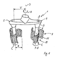
- Stirring tool 1 shown consists of a horizontal in normal position of use base 2, which is like a carrier on both sides of its vertical axis of rotation. 3 extends. In the region of the axis of rotation 3, the base part 2 is driven by means of a drive shaft, not shown, in the direction of the arrow A.
- the drive shaft can for example be integrally formed on the base part 2 or rotatably inserted into this.
- the base part 2 is preferably made by injection molding of plastic, e.g. a material of 65 wt .-% PA66, 20 wt .-% carbon fiber and 15 wt .-% PTFE, optionally with a reinforcing metal insert.
- plastic e.g. a material of 65 wt .-% PA66, 20 wt .-% carbon fiber and 15 wt .-% PTFE, optionally with a reinforcing metal insert.
- the bearing of the shaft 6 is formed so that it can rotate freely around its parallel axis of rotation 8, that is as low-friction as possible and without direct drive.
- Such a bearing can be formed for example by two ball bearings, which are coaxial with the axis of rotation 8, but axially spaced from each other, are arranged in the respective extension 5. Since a drive means for the paddle 7 is not provided, the design effort is relatively low.
- the agitator blades 11 are preferably made in one piece with the shaft 6 also by injection molding of plastic, eg a material of 65 wt .-% PA66, 20 wt .-% carbon fiber and 15 wt .-% PTFE, optionally with a reinforcing metal insert.
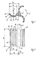
- the stirring vanes 11 have in lateral view, as from Fig.
- each stirring blade 11 deletes a circle with the radius R when the shaft 6 rotates about the axis of rotation 8.
- the radius R of the paddle 7 corresponds, as in Fig. 1 shown, about 0.6 times the offset V between the axis of rotation 3 of the base part 2 and the axis of rotation 8 of the paddle 7.
- the respective inner paddles 11 are thus clearly spaced from one another.
- the radius r of the arcuate curvature of each impeller 11 is about 0.6 times the width B of the lateral projection of the impeller 11, so that the impellers 11 form in cross-section a circular ring sector which is made slightly smaller than a semicircle, the edge 12 protrudes like a scraper.
- the height H of the impeller 11 is measured in dependence on the recommended level in the mixing vessel, not shown.
- the impellers 11 are further provided with a number of mutually parallel spaced vertical slots 13 which extend over a substantial part of the height H of the impellers 11.
- the slots 13 are not designed open edge, so that above and below the slots 13 each have a web 14 of the stirring blade 11 remains.
- the agitator blades 11 thereby still have a relatively high rigidity despite the weakening.
- the stirring tool 1 placed on a food processor is introduced from above into a preferably cylindrical mixing vessel until the vane stirrers 7 are only spaced from the bottom of the stirring vessel by a gap.
- the level of the mixing vessel is chosen so that the material to be stirred reaches above the height H of the stirring blades 11.
- the food processor is turned on, whereby the not immersed in the stirring material base 2 of the stirring tool 1 is rotated in the direction of arrow A in rotation.
- the rotation of the paddle 7 agitating be promoted in the direction of the center of the non-swept by the impellers 11 volume of the mixing vessel, so that there already displaced stirring material is re-supplied to the stirring process.
- the speed for the drive of the base part is preferably between 600 and 900 revolutions per minute.
Landscapes
- Chemical & Material Sciences (AREA)
- Chemical Kinetics & Catalysis (AREA)
- Engineering & Computer Science (AREA)
- Mechanical Engineering (AREA)
- Food Science & Technology (AREA)
- Mixers Of The Rotary Stirring Type (AREA)
- Food-Manufacturing Devices (AREA)
Claims (14)
- Agitateur (1) pour un appareil ménager, comprenant une pièce de base (2) rotative autour d'un axe de rotation (3) et au moins un agitateur à ailettes (7) qui est logé en tournant librement dans la pièce de base (2) et dont l'axe de rotation (8), par rapport à l'axe de rotation (3) de la pièce de base (2), est disposé de manière radialement décalée, au moins deux ailettes d'agitation (11) s'étendant radialement de l'axe de rotation (8) de l'agitateur à ailettes (7) vers l'extérieur, et le coefficient de résistance à l'écoulement des ailettes d'agitation (11) étant différent lors du soufflage du côté avant et du côté arrière, le contour extérieur des ailettes d'agitation (11) s'étendant essentiellement de manière équidistante par rapport à l'axe de rotation (8) de l'agitateur à ailettes (7), caractérisé en ce que les ailettes d'agitation (11) présentent des fentes (13).
- Agitateur selon la revendication 1, caractérisé en ce que les ailettes d'agitation (11) sont courbées de manière arquée dans une direction perpendiculaire à l'axe de rotation (8) de l'agitateur à ailettes (7).
- Agitateur selon la revendication 1 ou 2, caractérisé en ce que le coefficient de résistance à l'écoulement de l'ailette d'agitation (11), lors de la rotation de la pièce de base (2), dans sa position la plus éloignée possible de l'arbre d'entraînement est plus grand que dans sa position la plus proche de l'arbre d'entraînement.
- Agitateur selon l'une quelconque des revendications précédentes, caractérisé en ce que la courbure est réalisée en forme d'arc de cercle.
- Agitateur selon la revendication 4, caractérisé en ce que le rayon (r) de la courbure correspond à 0,5 jusqu'à 0,7 fois, de préférence à 0,6 fois, l'étendue radiale (largeur B) des ailettes d'agitation (11).
- Agitateur selon l'une quelconque des revendications 4 ou 6, caractérisé en ce que le point central de courbure de l'ailette d'agitation (11) respectivement située radialement à l'extérieur est disposé au-delà de son côté avant.
- Agitateur selon l'une quelconque des revendications précédentes, caractérisé en ce que les axes de rotation (8) des agitateurs à ailettes (7) sont orientés parallèlement à l'axe de rotation (3) de la pièce de base (2) de l'agitateur (1).
- Agitateur selon la revendication 7, caractérisé en ce que l'étendue radiale (largeur B) des ailettes d'agitation (11) correspond à 0,4 jusqu'à 0,8 fois, notamment à environ 0,6 fois le déport (V) entre l'axe de rotation (3) de la pièce de base (2) et l'axe de rotation (8) de l'agitateur à ailettes (7).
- Agitateur selon la revendication 1, caractérisé en ce que les fentes (13) s'étendent parallèlement à l'axe de rotation (8) de l'agitateur à ailettes (7).
- Agitateur selon l'une quelconque des revendications précédentes, caractérisé en ce que les agitateurs à ailettes (7) et/ou les ailettes d'agitation (11) sont ménagés de manière amovible et/ou interchangeable.
- Agitateur selon l'une quelconque des revendications précédentes, caractérisé en ce que les ailettes d'agitation (11) sont appliquées contre un tronc (6) dont l'extrémité en saillie est logée de manière rotative dans la pièce de base (2).
- Agitateur selon l'une quelconque des revendications précédentes, caractérisé en ce que la pièce de base (2) présente deux bras (4) diamétralement opposés l'un à l'autre, sur lesquels est respectivement disposé un agitateur à ailettes (7).
- Agitateur selon l'une quelconque des revendications précédentes, caractérisé en ce que les ailettes d'agitation (11) sont disposées en étant réparties régulièrement sur la circonférence de l'agitateur à ailettes (7).
- Agitateur selon la revendication 12, caractérisé en ce que chaque agitateur à ailettes (8) présente trois ailettes d'agitation (11).
Priority Applications (1)
| Application Number | Priority Date | Filing Date | Title |
|---|---|---|---|
| SI200930538T SI2326226T1 (sl) | 2008-07-02 | 2009-07-01 | Mešalno orodje za kuhinjski strojček |
Applications Claiming Priority (2)
| Application Number | Priority Date | Filing Date | Title |
|---|---|---|---|
| DE102008031247A DE102008031247A1 (de) | 2008-07-02 | 2008-07-02 | Rührwerkzeug, insbesondere für ein Küchengerät |
| PCT/EP2009/058249 WO2010000772A2 (fr) | 2008-07-02 | 2009-07-01 | Agitateur, en particulier pour appareil ménager |
Publications (2)
| Publication Number | Publication Date |
|---|---|
| EP2326226A2 EP2326226A2 (fr) | 2011-06-01 |
| EP2326226B1 true EP2326226B1 (fr) | 2012-12-26 |
Family
ID=41396663
Family Applications (1)
| Application Number | Title | Priority Date | Filing Date |
|---|---|---|---|
| EP09772472A Active EP2326226B1 (fr) | 2008-07-02 | 2009-07-01 | Agitateur pour appareil ménager |
Country Status (4)
| Country | Link |
|---|---|
| EP (1) | EP2326226B1 (fr) |
| DE (1) | DE102008031247A1 (fr) |
| SI (1) | SI2326226T1 (fr) |
| WO (1) | WO2010000772A2 (fr) |
Cited By (1)
| Publication number | Priority date | Publication date | Assignee | Title |
|---|---|---|---|---|
| CN107596942A (zh) * | 2017-08-01 | 2018-01-19 | 曾凡友 | 一种喷涂用喷涂液配制设备 |
Families Citing this family (7)
| Publication number | Priority date | Publication date | Assignee | Title |
|---|---|---|---|---|
| GB2497085B (en) * | 2011-11-29 | 2017-12-06 | Kenwood Ltd | Food cutter plate |
| CN103584751A (zh) * | 2012-08-17 | 2014-02-19 | 李文庆 | 一种打蛋器的改良机构 |
| CN107617355A (zh) * | 2017-10-31 | 2018-01-23 | 天津仁义合自动化技术股份有限公司 | 一种用于灌装机的混合设备 |
| FR3079125B1 (fr) | 2018-03-23 | 2023-01-20 | Seb Sa | Accessoire batteur pour un appareil electromenager de preparation culinaire, equipe de fouet(s) facilement demontable(s) |
| FR3079124B1 (fr) | 2018-03-23 | 2021-03-05 | Seb Sa | Accessoire batteur pour un appareil electromenager de preparation culinaire, adapte au melange de faibles quantites de preparation alimentaire |
| CN108772948A (zh) * | 2018-05-31 | 2018-11-09 | 浙江省建材集团建筑产业化有限公司 | 一种建筑桩基施工用泥浆搅拌器 |
| CN110479152B (zh) * | 2019-04-26 | 2024-07-02 | 天津科技大学 | 一种适用于高粘流体混合的导流式搅拌装置 |
Family Cites Families (11)
| Publication number | Priority date | Publication date | Assignee | Title |
|---|---|---|---|---|
| US2170280A (en) | 1938-10-10 | 1939-08-22 | John H Sharp | Churn |
| GB667863A (en) | 1950-01-24 | 1952-03-12 | Knud Viktor Hansen Christiense | Kneading or mixing member for use in mixing machines |
| DE906921C (de) * | 1951-01-13 | 1954-03-18 | Wilhelm Batz | Auf einen Schuesselrand aufsetzbares Ruehrgeraet |
| DE967158C (de) * | 1952-03-18 | 1957-10-10 | Fritz Hecht | Ruehrwerk fuer Einzellen-Dauererhitzer fuer milchwirtschaftliche Zwecke |
| DE2440809A1 (de) | 1974-08-26 | 1976-03-18 | Hans Kimmel | Ruehrwerkzeug fuer einen mischer oder ruehrer |
| US4148590A (en) * | 1975-09-25 | 1979-04-10 | Dr. Ing. Hans Muller | Apparatus and method of stirring fluids |
| CH597907A5 (fr) | 1975-09-25 | 1978-04-14 | Mueller Hans Maennedorf | |
| US4068832A (en) | 1975-12-08 | 1978-01-17 | Kraft, Inc. | Dasher |
| US4176970A (en) | 1975-12-08 | 1979-12-04 | Kraft, Inc. | Dasher |
| JP2833067B2 (ja) | 1989-10-31 | 1998-12-09 | 株式会社島津製作所 | 撹拌装置 |
| FR2773698B1 (fr) | 1998-01-22 | 2000-05-12 | Ronic Ind | Dispositif a fouet pour appareil de preparation culinaire |
-
2008
- 2008-07-02 DE DE102008031247A patent/DE102008031247A1/de not_active Withdrawn
-
2009
- 2009-07-01 SI SI200930538T patent/SI2326226T1/sl unknown
- 2009-07-01 WO PCT/EP2009/058249 patent/WO2010000772A2/fr not_active Ceased
- 2009-07-01 EP EP09772472A patent/EP2326226B1/fr active Active
Cited By (1)
| Publication number | Priority date | Publication date | Assignee | Title |
|---|---|---|---|---|
| CN107596942A (zh) * | 2017-08-01 | 2018-01-19 | 曾凡友 | 一种喷涂用喷涂液配制设备 |
Also Published As
| Publication number | Publication date |
|---|---|
| WO2010000772A2 (fr) | 2010-01-07 |
| EP2326226A2 (fr) | 2011-06-01 |
| DE102008031247A1 (de) | 2010-01-07 |
| WO2010000772A3 (fr) | 2011-07-07 |
| SI2326226T1 (sl) | 2013-04-30 |
Similar Documents
| Publication | Publication Date | Title |
|---|---|---|
| EP2326226B1 (fr) | Agitateur pour appareil ménager | |
| DE69704772T2 (de) | Mixbecher | |
| EP2421635B1 (fr) | Outil de cisaillement/mélange | |
| DE69932115T2 (de) | Rührwerk mit senkrechter Achse | |
| EP1639928B1 (fr) | Ensemble de lames pour un robot ménager a commande électromotrice et robot ménager correspondant | |
| DE102007056711A1 (de) | Knet- und Rührwerkzeug und Küchenmaschine | |
| EP2291104B1 (fr) | Robot ménager, en particulier pour le pétrissage de pâte | |
| EP2269491A1 (fr) | Outil de malaxage pour pâtes lourdes | |
| DE3610740C2 (fr) | ||
| DE3433008A1 (de) | Kuechenmaschine, insbesondere mehrzweck-kuechenmaschine | |
| EP0799593B1 (fr) | Outil de mixage pour un appareil de cuisine pour mélanger et mousser de la nourriture | |
| EP0678269B1 (fr) | Batteur-mélangeur | |
| DE102019124886A1 (de) | Rührorganvorrichtung | |
| EP3342480A1 (fr) | Outil de mélange pour un mélangeur et mélangeur | |
| DD141780A6 (de) | Ruehrgeraet mit zugehoeriger strangpresse zur herstellung von teigen | |
| DE1140440B (de) | Zerkleinerungs-, Ruehr- und Mischvorrichtung | |
| DE19504033C2 (de) | Flügelscheibe für Rührwellen | |
| DE1554642A1 (de) | Mehrarmiges Ruehr- und Knetwerkzeug fuer die Ruehrschuessel einer elektrisch angetriebenen Haushalt-Kuechenmaschine | |
| DE202009009041U1 (de) | Drehmomentgünstiges Rührwerkzeug | |
| DE3144438A1 (de) | Kuechenmaschine mit motorischem antrieb | |
| DE69404633T2 (de) | Mixgerät für lebensmittel | |
| DE69628047T2 (de) | Rührvorrchtung für ein automatisches kochgerät | |
| DE1300213B (de) | Knet- und Ruehrgeraet | |
| DE202024101064U1 (de) | Küchenmaschine | |
| EP2269494A1 (fr) | Elément de tête pour un outil de malaxage |
Legal Events
| Date | Code | Title | Description |
|---|---|---|---|
| PUAI | Public reference made under article 153(3) epc to a published international application that has entered the european phase |
Free format text: ORIGINAL CODE: 0009012 |
|
| AK | Designated contracting states |
Kind code of ref document: A2 Designated state(s): AT BE BG CH CY CZ DE DK EE ES FI FR GB GR HR HU IE IS IT LI LT LU LV MC MK MT NL NO PL PT RO SE SI SK SM TR |
|
| AX | Request for extension of the european patent |
Extension state: AL BA RS |
|
| 17P | Request for examination filed |
Effective date: 20120109 |
|
| RBV | Designated contracting states (corrected) |
Designated state(s): AT BE BG CH CY CZ DE DK EE ES FI FR GB GR HR HU IE IS IT LI LT LU LV MC MK MT NL NO PL PT RO SE SI SK SM TR |
|
| DAX | Request for extension of the european patent (deleted) | ||
| GRAP | Despatch of communication of intention to grant a patent |
Free format text: ORIGINAL CODE: EPIDOSNIGR1 |
|
| GRAS | Grant fee paid |
Free format text: ORIGINAL CODE: EPIDOSNIGR3 |
|
| GRAA | (expected) grant |
Free format text: ORIGINAL CODE: 0009210 |
|
| AK | Designated contracting states |
Kind code of ref document: B1 Designated state(s): AT BE BG CH CY CZ DE DK EE ES FI FR GB GR HR HU IE IS IT LI LT LU LV MC MK MT NL NO PL PT RO SE SI SK SM TR |
|
| REG | Reference to a national code |
Ref country code: GB Ref legal event code: FG4D Free format text: NOT ENGLISH |
|
| REG | Reference to a national code |
Ref country code: CH Ref legal event code: EP |
|
| REG | Reference to a national code |
Ref country code: AT Ref legal event code: REF Ref document number: 590001 Country of ref document: AT Kind code of ref document: T Effective date: 20130115 |
|
| REG | Reference to a national code |
Ref country code: DE Ref legal event code: R096 Ref document number: 502009005814 Country of ref document: DE Effective date: 20130228 |
|
| PG25 | Lapsed in a contracting state [announced via postgrant information from national office to epo] |
Ref country code: HR Free format text: LAPSE BECAUSE OF FAILURE TO SUBMIT A TRANSLATION OF THE DESCRIPTION OR TO PAY THE FEE WITHIN THE PRESCRIBED TIME-LIMIT Effective date: 20121226 Ref country code: LT Free format text: LAPSE BECAUSE OF FAILURE TO SUBMIT A TRANSLATION OF THE DESCRIPTION OR TO PAY THE FEE WITHIN THE PRESCRIBED TIME-LIMIT Effective date: 20121226 Ref country code: SE Free format text: LAPSE BECAUSE OF FAILURE TO SUBMIT A TRANSLATION OF THE DESCRIPTION OR TO PAY THE FEE WITHIN THE PRESCRIBED TIME-LIMIT Effective date: 20121226 Ref country code: FI Free format text: LAPSE BECAUSE OF FAILURE TO SUBMIT A TRANSLATION OF THE DESCRIPTION OR TO PAY THE FEE WITHIN THE PRESCRIBED TIME-LIMIT Effective date: 20121226 Ref country code: NO Free format text: LAPSE BECAUSE OF FAILURE TO SUBMIT A TRANSLATION OF THE DESCRIPTION OR TO PAY THE FEE WITHIN THE PRESCRIBED TIME-LIMIT Effective date: 20130326 |
|
| REG | Reference to a national code |
Ref country code: LT Ref legal event code: MG4D |
|
| REG | Reference to a national code |
Ref country code: NL Ref legal event code: VDEP Effective date: 20121226 |
|
| PG25 | Lapsed in a contracting state [announced via postgrant information from national office to epo] |
Ref country code: LV Free format text: LAPSE BECAUSE OF FAILURE TO SUBMIT A TRANSLATION OF THE DESCRIPTION OR TO PAY THE FEE WITHIN THE PRESCRIBED TIME-LIMIT Effective date: 20121226 Ref country code: GR Free format text: LAPSE BECAUSE OF FAILURE TO SUBMIT A TRANSLATION OF THE DESCRIPTION OR TO PAY THE FEE WITHIN THE PRESCRIBED TIME-LIMIT Effective date: 20130327 |
|
| REG | Reference to a national code |
Ref country code: HU Ref legal event code: AG4A Ref document number: E015885 Country of ref document: HU |
|
| PG25 | Lapsed in a contracting state [announced via postgrant information from national office to epo] |
Ref country code: ES Free format text: LAPSE BECAUSE OF FAILURE TO SUBMIT A TRANSLATION OF THE DESCRIPTION OR TO PAY THE FEE WITHIN THE PRESCRIBED TIME-LIMIT Effective date: 20130406 Ref country code: EE Free format text: LAPSE BECAUSE OF FAILURE TO SUBMIT A TRANSLATION OF THE DESCRIPTION OR TO PAY THE FEE WITHIN THE PRESCRIBED TIME-LIMIT Effective date: 20121226 Ref country code: SK Free format text: LAPSE BECAUSE OF FAILURE TO SUBMIT A TRANSLATION OF THE DESCRIPTION OR TO PAY THE FEE WITHIN THE PRESCRIBED TIME-LIMIT Effective date: 20121226 Ref country code: CZ Free format text: LAPSE BECAUSE OF FAILURE TO SUBMIT A TRANSLATION OF THE DESCRIPTION OR TO PAY THE FEE WITHIN THE PRESCRIBED TIME-LIMIT Effective date: 20121226 Ref country code: BG Free format text: LAPSE BECAUSE OF FAILURE TO SUBMIT A TRANSLATION OF THE DESCRIPTION OR TO PAY THE FEE WITHIN THE PRESCRIBED TIME-LIMIT Effective date: 20130326 Ref country code: IS Free format text: LAPSE BECAUSE OF FAILURE TO SUBMIT A TRANSLATION OF THE DESCRIPTION OR TO PAY THE FEE WITHIN THE PRESCRIBED TIME-LIMIT Effective date: 20130426 |
|
| PG25 | Lapsed in a contracting state [announced via postgrant information from national office to epo] |
Ref country code: NL Free format text: LAPSE BECAUSE OF FAILURE TO SUBMIT A TRANSLATION OF THE DESCRIPTION OR TO PAY THE FEE WITHIN THE PRESCRIBED TIME-LIMIT Effective date: 20121226 Ref country code: PT Free format text: LAPSE BECAUSE OF FAILURE TO SUBMIT A TRANSLATION OF THE DESCRIPTION OR TO PAY THE FEE WITHIN THE PRESCRIBED TIME-LIMIT Effective date: 20130426 Ref country code: RO Free format text: LAPSE BECAUSE OF FAILURE TO SUBMIT A TRANSLATION OF THE DESCRIPTION OR TO PAY THE FEE WITHIN THE PRESCRIBED TIME-LIMIT Effective date: 20121226 Ref country code: PL Free format text: LAPSE BECAUSE OF FAILURE TO SUBMIT A TRANSLATION OF THE DESCRIPTION OR TO PAY THE FEE WITHIN THE PRESCRIBED TIME-LIMIT Effective date: 20121226 |
|
| PG25 | Lapsed in a contracting state [announced via postgrant information from national office to epo] |
Ref country code: DK Free format text: LAPSE BECAUSE OF FAILURE TO SUBMIT A TRANSLATION OF THE DESCRIPTION OR TO PAY THE FEE WITHIN THE PRESCRIBED TIME-LIMIT Effective date: 20121226 |
|
| PLBE | No opposition filed within time limit |
Free format text: ORIGINAL CODE: 0009261 |
|
| STAA | Information on the status of an ep patent application or granted ep patent |
Free format text: STATUS: NO OPPOSITION FILED WITHIN TIME LIMIT |
|
| PG25 | Lapsed in a contracting state [announced via postgrant information from national office to epo] |
Ref country code: CY Free format text: LAPSE BECAUSE OF FAILURE TO SUBMIT A TRANSLATION OF THE DESCRIPTION OR TO PAY THE FEE WITHIN THE PRESCRIBED TIME-LIMIT Effective date: 20121226 |
|
| 26N | No opposition filed |
Effective date: 20130927 |
|
| REG | Reference to a national code |
Ref country code: DE Ref legal event code: R097 Ref document number: 502009005814 Country of ref document: DE Effective date: 20130927 |
|
| BERE | Be: lapsed |
Owner name: BSH BOSCH UND SIEMENS HAUSGERATE G.M.B.H. Effective date: 20130731 |
|
| PG25 | Lapsed in a contracting state [announced via postgrant information from national office to epo] |
Ref country code: MC Free format text: LAPSE BECAUSE OF FAILURE TO SUBMIT A TRANSLATION OF THE DESCRIPTION OR TO PAY THE FEE WITHIN THE PRESCRIBED TIME-LIMIT Effective date: 20121226 |
|
| REG | Reference to a national code |
Ref country code: CH Ref legal event code: PL |
|
| GBPC | Gb: european patent ceased through non-payment of renewal fee |
Effective date: 20130701 |
|
| REG | Reference to a national code |
Ref country code: IE Ref legal event code: MM4A |
|
| PG25 | Lapsed in a contracting state [announced via postgrant information from national office to epo] |
Ref country code: GB Free format text: LAPSE BECAUSE OF NON-PAYMENT OF DUE FEES Effective date: 20130701 Ref country code: BE Free format text: LAPSE BECAUSE OF NON-PAYMENT OF DUE FEES Effective date: 20130731 Ref country code: CH Free format text: LAPSE BECAUSE OF NON-PAYMENT OF DUE FEES Effective date: 20130731 Ref country code: LI Free format text: LAPSE BECAUSE OF NON-PAYMENT OF DUE FEES Effective date: 20130731 |
|
| PG25 | Lapsed in a contracting state [announced via postgrant information from national office to epo] |
Ref country code: IE Free format text: LAPSE BECAUSE OF NON-PAYMENT OF DUE FEES Effective date: 20130701 |
|
| REG | Reference to a national code |
Ref country code: DE Ref legal event code: R081 Ref document number: 502009005814 Country of ref document: DE Owner name: BSH HAUSGERAETE GMBH, DE Free format text: FORMER OWNER: BSH BOSCH UND SIEMENS HAUSGERAETE GMBH, 81739 MUENCHEN, DE Effective date: 20150407 |
|
| PG25 | Lapsed in a contracting state [announced via postgrant information from national office to epo] |
Ref country code: SM Free format text: LAPSE BECAUSE OF FAILURE TO SUBMIT A TRANSLATION OF THE DESCRIPTION OR TO PAY THE FEE WITHIN THE PRESCRIBED TIME-LIMIT Effective date: 20121226 |
|
| PG25 | Lapsed in a contracting state [announced via postgrant information from national office to epo] |
Ref country code: MT Free format text: LAPSE BECAUSE OF FAILURE TO SUBMIT A TRANSLATION OF THE DESCRIPTION OR TO PAY THE FEE WITHIN THE PRESCRIBED TIME-LIMIT Effective date: 20121226 |
|
| REG | Reference to a national code |
Ref country code: SI Ref legal event code: SP73 Owner name: BSH HAUSGERAETE GMBH; DE Effective date: 20150529 |
|
| REG | Reference to a national code |
Ref country code: FR Ref legal event code: PLFP Year of fee payment: 7 |
|
| PG25 | Lapsed in a contracting state [announced via postgrant information from national office to epo] |
Ref country code: MK Free format text: LAPSE BECAUSE OF FAILURE TO SUBMIT A TRANSLATION OF THE DESCRIPTION OR TO PAY THE FEE WITHIN THE PRESCRIBED TIME-LIMIT Effective date: 20121226 Ref country code: LU Free format text: LAPSE BECAUSE OF NON-PAYMENT OF DUE FEES Effective date: 20130701 |
|
| REG | Reference to a national code |
Ref country code: HU Ref legal event code: HC9C Owner name: BSH HAUSGERAETE GMBH, DE Free format text: FORMER OWNER(S): BSH BOSCH UND SIEMENS HAUSGERAETE GMBH, DE |
|
| REG | Reference to a national code |
Ref country code: AT Ref legal event code: MM01 Ref document number: 590001 Country of ref document: AT Kind code of ref document: T Effective date: 20140701 |
|
| REG | Reference to a national code |
Ref country code: FR Ref legal event code: CD Owner name: BSH HAUSGERATE GMBH, DE Effective date: 20151022 |
|
| PG25 | Lapsed in a contracting state [announced via postgrant information from national office to epo] |
Ref country code: AT Free format text: LAPSE BECAUSE OF NON-PAYMENT OF DUE FEES Effective date: 20140701 |
|
| REG | Reference to a national code |
Ref country code: FR Ref legal event code: PLFP Year of fee payment: 8 |
|
| REG | Reference to a national code |
Ref country code: FR Ref legal event code: PLFP Year of fee payment: 9 |
|
| REG | Reference to a national code |
Ref country code: FR Ref legal event code: PLFP Year of fee payment: 10 |
|
| PGFP | Annual fee paid to national office [announced via postgrant information from national office to epo] |
Ref country code: TR Payment date: 20220624 Year of fee payment: 14 |
|
| PGFP | Annual fee paid to national office [announced via postgrant information from national office to epo] |
Ref country code: IT Payment date: 20220729 Year of fee payment: 14 Ref country code: DE Payment date: 20220731 Year of fee payment: 14 |
|
| PGFP | Annual fee paid to national office [announced via postgrant information from national office to epo] |
Ref country code: SI Payment date: 20220623 Year of fee payment: 14 Ref country code: HU Payment date: 20220625 Year of fee payment: 14 Ref country code: FR Payment date: 20220725 Year of fee payment: 14 |
|
| REG | Reference to a national code |
Ref country code: DE Ref legal event code: R119 Ref document number: 502009005814 Country of ref document: DE |
|
| PG25 | Lapsed in a contracting state [announced via postgrant information from national office to epo] |
Ref country code: HU Free format text: LAPSE BECAUSE OF NON-PAYMENT OF DUE FEES Effective date: 20230702 Ref country code: DE Free format text: LAPSE BECAUSE OF NON-PAYMENT OF DUE FEES Effective date: 20240201 |
|
| PG25 | Lapsed in a contracting state [announced via postgrant information from national office to epo] |
Ref country code: SI Free format text: LAPSE BECAUSE OF NON-PAYMENT OF DUE FEES Effective date: 20230702 |
|
| PG25 | Lapsed in a contracting state [announced via postgrant information from national office to epo] |
Ref country code: SI Free format text: LAPSE BECAUSE OF NON-PAYMENT OF DUE FEES Effective date: 20230702 Ref country code: FR Free format text: LAPSE BECAUSE OF NON-PAYMENT OF DUE FEES Effective date: 20230731 |
|
| REG | Reference to a national code |
Ref country code: SI Ref legal event code: KO00 Effective date: 20240423 |
|
| PG25 | Lapsed in a contracting state [announced via postgrant information from national office to epo] |
Ref country code: IT Free format text: LAPSE BECAUSE OF NON-PAYMENT OF DUE FEES Effective date: 20230701 |