EP2226440A2 - Elément de ferrure - Google Patents
Elément de ferrure Download PDFInfo
- Publication number
- EP2226440A2 EP2226440A2 EP10154971A EP10154971A EP2226440A2 EP 2226440 A2 EP2226440 A2 EP 2226440A2 EP 10154971 A EP10154971 A EP 10154971A EP 10154971 A EP10154971 A EP 10154971A EP 2226440 A2 EP2226440 A2 EP 2226440A2
- Authority
- EP
- European Patent Office
- Prior art keywords
- fitting
- counter
- element according
- passage
- cone
- Prior art date
- Legal status (The legal status is an assumption and is not a legal conclusion. Google has not performed a legal analysis and makes no representation as to the accuracy of the status listed.)
- Withdrawn
Links
- 229910052751 metal Inorganic materials 0.000 description 24
- 239000002184 metal Substances 0.000 description 18
- 239000002023 wood Substances 0.000 description 11
- 238000011161 development Methods 0.000 description 4
- 230000018109 developmental process Effects 0.000 description 4
- 229910000831 Steel Inorganic materials 0.000 description 2
- 230000005540 biological transmission Effects 0.000 description 2
- 230000000295 complement effect Effects 0.000 description 2
- 238000010276 construction Methods 0.000 description 2
- 239000010959 steel Substances 0.000 description 2
- 230000007704 transition Effects 0.000 description 2
- FGRBYDKOBBBPOI-UHFFFAOYSA-N 10,10-dioxo-2-[4-(N-phenylanilino)phenyl]thioxanthen-9-one Chemical compound O=C1c2ccccc2S(=O)(=O)c2ccc(cc12)-c1ccc(cc1)N(c1ccccc1)c1ccccc1 FGRBYDKOBBBPOI-UHFFFAOYSA-N 0.000 description 1
- TVEXGJYMHHTVKP-UHFFFAOYSA-N 6-oxabicyclo[3.2.1]oct-3-en-7-one Chemical compound C1C2C(=O)OC1C=CC2 TVEXGJYMHHTVKP-UHFFFAOYSA-N 0.000 description 1
- 229910052729 chemical element Inorganic materials 0.000 description 1
- 210000003608 fece Anatomy 0.000 description 1
- 239000007787 solid Substances 0.000 description 1
Images


Classifications
-
- E—FIXED CONSTRUCTIONS
- E04—BUILDING
- E04B—GENERAL BUILDING CONSTRUCTIONS; WALLS, e.g. PARTITIONS; ROOFS; FLOORS; CEILINGS; INSULATION OR OTHER PROTECTION OF BUILDINGS
- E04B1/00—Constructions in general; Structures which are not restricted either to walls, e.g. partitions, or floors or ceilings or roofs
- E04B1/18—Structures comprising elongated load-supporting parts, e.g. columns, girders, skeletons
- E04B1/26—Structures comprising elongated load-supporting parts, e.g. columns, girders, skeletons the supporting parts consisting of wood
-
- F—MECHANICAL ENGINEERING; LIGHTING; HEATING; WEAPONS; BLASTING
- F16—ENGINEERING ELEMENTS AND UNITS; GENERAL MEASURES FOR PRODUCING AND MAINTAINING EFFECTIVE FUNCTIONING OF MACHINES OR INSTALLATIONS; THERMAL INSULATION IN GENERAL
- F16B—DEVICES FOR FASTENING OR SECURING CONSTRUCTIONAL ELEMENTS OR MACHINE PARTS TOGETHER, e.g. NAILS, BOLTS, CIRCLIPS, CLAMPS, CLIPS OR WEDGES; JOINTS OR JOINTING
- F16B43/00—Washers or equivalent devices; Other devices for supporting bolt-heads or nuts
- F16B43/02—Washers or equivalent devices; Other devices for supporting bolt-heads or nuts with special provisions for engaging surfaces which are not perpendicular to a bolt axis or do not surround the bolt
-
- E—FIXED CONSTRUCTIONS
- E04—BUILDING
- E04B—GENERAL BUILDING CONSTRUCTIONS; WALLS, e.g. PARTITIONS; ROOFS; FLOORS; CEILINGS; INSULATION OR OTHER PROTECTION OF BUILDINGS
- E04B1/00—Constructions in general; Structures which are not restricted either to walls, e.g. partitions, or floors or ceilings or roofs
- E04B1/18—Structures comprising elongated load-supporting parts, e.g. columns, girders, skeletons
- E04B1/26—Structures comprising elongated load-supporting parts, e.g. columns, girders, skeletons the supporting parts consisting of wood
- E04B1/2604—Connections specially adapted therefor
-
- E—FIXED CONSTRUCTIONS
- E04—BUILDING
- E04B—GENERAL BUILDING CONSTRUCTIONS; WALLS, e.g. PARTITIONS; ROOFS; FLOORS; CEILINGS; INSULATION OR OTHER PROTECTION OF BUILDINGS
- E04B1/00—Constructions in general; Structures which are not restricted either to walls, e.g. partitions, or floors or ceilings or roofs
- E04B1/18—Structures comprising elongated load-supporting parts, e.g. columns, girders, skeletons
- E04B1/26—Structures comprising elongated load-supporting parts, e.g. columns, girders, skeletons the supporting parts consisting of wood
- E04B1/2604—Connections specially adapted therefor
- E04B2001/2652—Details of nailing, screwing, or bolting
Definitions
- the invention relates to a fitting part similar to a washer.
- the invention is based on the object to provide a fitting element by means of which it is possible to attach metal parts to wood in such a way that a load of the pin-shaped fasteners takes place predominantly in the pulling direction.
- the invention proposes a fitting element with the features of claim 1.
- the invention also proposes a fitting counter-element, which can be attached to the fitting element on a wooden component.
- the invention further proposes the use of a fitting element.
- the fitting element proposed by the invention thus has one Outer circumference, which lies in a conical surface.
- the passage for a screw runs obliquely with respect to the axis of the cone.
- a to be fastened to a wooden component metal element with a bore is now provided with a countersink.
- the countersink must have the same angle as the fitting element.
- the fitting element which acts like a washer, now the metal element is screwed to the wood, the screw then also runs obliquely to the surface of the timber component. If a force is now exerted on the metal element in the direction of the surface of the wooden component, this results in a loading of the screw in the axial direction and not to a load on shear.
- any conical shapes are possible, however, for reasons of simplicity in a further development, a straight circular cone is preferred. This is especially true when a countersinking is to be performed by means of a drill on the metal component to be screwed.
- the contact surface is sunk for the underside of the screw head in the fitting element.
- a countersunk screw is preferred.
- the fitting element proposed by the invention may have approximately the shape of a disk, ie have a flat bottom and a flat top.
- the fitting element can also be simplified, since only the contact surface for the underside of the screw head and on the other hand, the contact surface between the outside of the fitting element and the inside of the countersink in the metal parts is used for power transmission.
- the fitting element can be designed asymmetrically and where the load is greater, stronger.
- the apex angle of the cone, on the conical surface of which lies the outer contour of the fitting element is in the range of approximately 90 °.
- the fitting element can serve, for example, to screw a metal profile to a wood element having holes provided with countersinks.
- the fitting element can be used for screwing any counter-elements, which must be given as the only requirement that this counter-element counterbores with the same point angle as the fitting element.
- this counter-fitting element has a rear side intended for engagement with a component consisting of wood, a front side opposite the rear side, and a passage between the front side and the rear side, which is delimited by a surface lying in a conical surface.
- a kind of funnel is formed with straight walls. The apex angle of this funnel must correspond to the tip wrench of the cone of the shell surface of the fitting element, so that the fitting element into the passage of the fitting counter element can be used. With the aid of the screw, the fitting element can therefore be inserted into the passage and thus screw the fitting counter-element tightly to the timber component.
- fitting counter-element may be formed according to the invention in the manner of a disc, in which case a rectangular or square shape is preferred to facilitate the alignment.
- the fitting counter element may also have a plurality of such funnel-shaped passages, in particular when a certain angular orientation of the fitting counter-element is to be achieved.
- the fitting counter-element can be made by the factory, its passage may also have other conical shapes than the shape of a straight circular cone.
- the fitting counter element in a further development can have an alignment device with the aid of which it is aligned with an adjacent fitting counter element.
- the adjacent fitting counter-element can be fastened to the same wooden component, or else to another wooden component.
- the alignment device can be realized for example by a complementary shape of facing boundary surfaces, or by additional aids such as holes and pins.
- the invention also proposes a combination of a fitting element and a fitting counter element.
- the two parts can be specially matched to each other.
- two wooden beams fitting elements and fittings counter elements according to the invention can be used according to the invention.
- a fitting counter element is screwed by means of a fitting element.
- the fitting counter element of a timber carrier can be placed on the fitting counter-element of the other wood support, wherein the alignment is a safeguard against lateral slipping.
- the weight of a timber carrier then acts on the fitting counter-element of the other timber carrier.
- the Figures 1 and 2 show the side view and the section of a fitting element according to the invention.
- the fitting element is formed as a disc. It contains a planar outer side 1 and a likewise flat inner side 2 running parallel to the latter. Between these two sides 1 and 2 extends the lateral surface 3, which lies in a conical surface and is closed in the exemplary embodiment shown.
- the conical surface is the conical surface of a circular cone.
- the fitting element extends a passage 4, which passes from the outside 1 to the inside 2 and extends obliquely.
- the passage 4 has a circular cross section everywhere.
- the axis of the passage 4 extends obliquely to the imaginary axis of the cone, on the lateral surface of the lateral surface 3 of the fitting element is located.
- the outlet opening 5 of the passage 4 is in the illustrated embodiment completely in the plane of the inner side of the second
- the passage 4 has a section 4 a with a larger diameter extending from the outside 1 and a section 4 b opening in the inside 2 with a smaller diameter. Between both sections 4a, 4b, a conical transition 6 is formed. The cone angle of this transition region 6 corresponds to the underside of a conventional screw head.
- the cone angle of the cone in whose lateral surface the lateral surface 3 of the fitting element is 90 ° in the illustrated embodiment.
- the axis of the passage 4 extends in the section of the FIG. 1 parallel to the generatrix so that the axis of the passage 4 on the opposite side is perpendicular to the generatrix.
- fitting element is intended to screw another element to a wooden structure.
- the other element for example a metal perforated belt or the like, must have an opening 10 into which the fitting element can be inserted.
- the opening must therefore be designed to be complementary to the outside of the fitting element. In the simplest case, it must be a passage opening with a countersink of the same angle, which corresponds to the cone angle of the lateral surface 3 of the fitting element.
- FIG. 3 shown in section.
- a metallic element 11 has the frusto-conical opening 10 into which the fitting element can be inserted.
- the fitting element abuts with its lateral surface against the inner surface 12 of the opening 10.
- a load occurs when tightening but only at certain points of the lateral surface 3, so that the fitting element not as a complete conical disk accordingly FIG. 1 and FIG. 2 must be trained. It is sufficient to form the fitting element only as a part of the conical disk. This is in FIG. 3 also shown.
- both the lateral surface 3 of the fitting element and the wall 12 of the recess 10 can be arranged on a conical surface which deviates from a circular cone, for example an elliptical cone.
- FIGS. 4 and 5 show a plan view and a section through an embodiment of such a fitting counter element. It's the simplest Fall in the FIGS. 4 and 5 is formed, designed as a flat disc, with a flat front side 15 and a parallel to this extending flat back 16. In this disc, the recess 10 is arranged, which does not differ in shape from the embodiment of Figure three. This continuous opening thus has a wall 12 which lies in a conical surface. How to get the FIG. 4 can be removed, it is also a circular cone, and the opening in the front 15 of the fitting counter-element opening of this recess 10 is bounded by an edge 17 in the form of a circle.
- This fitting counter-element can be screwed with a fitting element to a wooden structure, similar to the embodiment according to FIG. 3 ,
- the holes 18 can be arranged on two opposite end faces 19, 20. These holes serve to receive pins, with which two fitting counter-elements can be aligned with each other.
- These stud-aligned fitting counterparts may be attached to the same component, or to two different components. Examples of this will be described later.
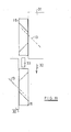
- FIG. 6 shows a top view of a fitting counter-element, in which one of the two lateral end edges 21 is offset stepwise. The step is exactly in the middle of the front edge, so that a second fitting counter element can be inserted in a 180 ° offset arrangement here.
- bores 18 are formed, which pass, for example, through the entire fitting counter element. The left bore 18 thus exits at the step 22.
- the fitting counter element of FIGS. 6 and 7 is slightly less thick than the fitting counter-element FIGS. 4 and 5 , so that the conical surface 12 limiting line 17 is only partially in the top 15. In other words, the conical surface 12 is formed only incomplete.
- FIGS. 6 and 7 on one side has a step 21, 22, shows the FIG. 8 and the FIG. 9 an embodiment in which an identical step 21, 22 is formed on two opposite lateral end edges.
- FIG. 10 shows a plan view of two fitting counter-elements of FIG. 6 , which are arranged side by side with the way that the steps 21, 22 intermesh. If these fittings counter elements with two fitting elements of FIGS. 1 and 2 bolted to a substructure and secured by a pin in the holes 18, both fitting counter-elements are secured against rotation about the axis of the hole 10.
- FIG. 11 shows a use case for fitting elements and fitting counterparts from the previous figures.
- another wood construction 31 is to be attached to a wooden structure 30.
- the load of the wooden structure 31 acts in the direction of the arrow 32.
- a fitting counter element is attached by means of a fitting element.
- the fitting element is inserted into the recess 10 in such a way that the passage 4 is oriented so that the fastening screw 13 is screwed in obliquely upward from the outside.
- the fitting counter-element is fixed to the wooden structure 30.
- the determination is made in such a way that the upper end face 19 of the fitting counter-element extends horizontally.
- a pin 33 is used at the wooden beam 31, which is to be connected to the construction 30, an identical or similar constructed counter-locking element is screwed with a fitting element.
- the fitting element is oriented in such a way that the screwed through the passage 4 screw 13, which is only indicated, is screwed from above obliquely downwards.
- the fitting counter-element of the beam 31 is aligned so that the pin 33 engages in the corresponding bore 18 of the upper fitting counter-element.
- the two wooden components 30, 31 are connected to each other.
- the load is absorbed by the screws 13, both of which are essentially stressed.
- the slipping of the upper beam 31 in a direction perpendicular to the plane of the paper or to the right is made by the engagement of the connecting pin 33 prevented in the bore 18.
Landscapes
- Engineering & Computer Science (AREA)
- Architecture (AREA)
- General Engineering & Computer Science (AREA)
- Physics & Mathematics (AREA)
- Electromagnetism (AREA)
- Civil Engineering (AREA)
- Structural Engineering (AREA)
- Mechanical Engineering (AREA)
- Joining Of Building Structures In Genera (AREA)
- Furniture Connections (AREA)
- Mutual Connection Of Rods And Tubes (AREA)
- Connection Of Plates (AREA)
Applications Claiming Priority (1)
| Application Number | Priority Date | Filing Date | Title |
|---|---|---|---|
| DE102009013146A DE102009013146A1 (de) | 2009-03-05 | 2009-03-05 | Beschlagelement |
Publications (2)
| Publication Number | Publication Date |
|---|---|
| EP2226440A2 true EP2226440A2 (fr) | 2010-09-08 |
| EP2226440A3 EP2226440A3 (fr) | 2011-03-30 |
Family
ID=42227721
Family Applications (1)
| Application Number | Title | Priority Date | Filing Date |
|---|---|---|---|
| EP10154971A Withdrawn EP2226440A3 (fr) | 2009-03-05 | 2010-02-27 | Elément de ferrure |
Country Status (2)
| Country | Link |
|---|---|
| EP (1) | EP2226440A3 (fr) |
| DE (1) | DE102009013146A1 (fr) |
Cited By (3)
| Publication number | Priority date | Publication date | Assignee | Title |
|---|---|---|---|---|
| DE102016125008A1 (de) * | 2016-12-20 | 2018-06-21 | Fischer Italia S.R.L. | Holz-Beton-Verbinder und Befestigungsanordnung |
| US10253801B2 (en) | 2015-09-29 | 2019-04-09 | Simpson Strong-Tie Company Inc. | Washer with shear tube |
| US12168992B2 (en) | 2021-08-05 | 2024-12-17 | The Hillman Group, Inc. | Hardware assembly |
Family Cites Families (12)
| Publication number | Priority date | Publication date | Assignee | Title |
|---|---|---|---|---|
| US3006443A (en) * | 1954-12-20 | 1961-10-31 | Joseph T Siler | Method and apparatus for attaching juxtaposed members |
| JPH044616Y2 (fr) * | 1985-10-14 | 1992-02-10 | ||
| IT1232572B (it) * | 1989-02-10 | 1992-02-26 | Calderale Pasquale Mario | Mezzi di osteosintesi per il collegamento di segmenti di fratture ossee |
| AT402597B (de) * | 1994-12-07 | 1997-06-25 | Blum Gmbh Julius | Möbelbeschlag, insbesondere verbindungsbeschlag möbelbeschlag, insbesondere verbindungsbeschlag |
| DE19505311C2 (de) * | 1995-02-17 | 2002-04-11 | Lautenschlaeger Mepla Werke | Befestigungsanordnung von Beschlägen, insbesondere Möbelbeschlägen an Möbelstücken |
| US5906466A (en) * | 1995-04-05 | 1999-05-25 | Eandi; Roger E. | Plug washer |
| DE29818605U1 (de) * | 1998-08-05 | 1998-12-24 | Arturo Salice S.P.A., Novedrate, Como | Beschlagteil |
| AT406895B (de) * | 1999-03-18 | 2000-10-25 | Blum Gmbh Julius | Beschlag zur lösbaren befestigung an einem möbelteil |
| DE20022759U1 (de) * | 2000-09-22 | 2002-05-23 | Sorg, Hartmut, 65375 Oestrich-Winkel | Beschlag für ein Möbelstück |
| DE202004017025U1 (de) * | 2004-11-02 | 2006-03-16 | Rehau Ag + Co. | Montagebeschlag zur Festlegung eines zu montierenden Gegenstandes an einem Tragelement sowie Baugruppe mit einem derartigen Montagebeschlag |
| ITBG20050045A1 (it) * | 2005-08-30 | 2007-02-28 | Matteo Gotti | Dispositivo per il collegamento di componenti di una struttura a pannelli. |
| DE202008017215U1 (de) * | 2008-12-22 | 2009-04-16 | Simpson Strong-Tie Gmbh | Zwischenelement für eine Schrägschraubverbindung |
-
2009
- 2009-03-05 DE DE102009013146A patent/DE102009013146A1/de not_active Withdrawn
-
2010
- 2010-02-27 EP EP10154971A patent/EP2226440A3/fr not_active Withdrawn
Non-Patent Citations (1)
| Title |
|---|
| None |
Cited By (4)
| Publication number | Priority date | Publication date | Assignee | Title |
|---|---|---|---|---|
| US10253801B2 (en) | 2015-09-29 | 2019-04-09 | Simpson Strong-Tie Company Inc. | Washer with shear tube |
| US11137016B2 (en) | 2015-09-29 | 2021-10-05 | Simpson Strong-Tie Company, Inc. | Washer with shear tube |
| DE102016125008A1 (de) * | 2016-12-20 | 2018-06-21 | Fischer Italia S.R.L. | Holz-Beton-Verbinder und Befestigungsanordnung |
| US12168992B2 (en) | 2021-08-05 | 2024-12-17 | The Hillman Group, Inc. | Hardware assembly |
Also Published As
| Publication number | Publication date |
|---|---|
| DE102009013146A1 (de) | 2010-09-09 |
| EP2226440A3 (fr) | 2011-03-30 |
Similar Documents
| Publication | Publication Date | Title |
|---|---|---|
| EP1961976B1 (fr) | Dispositif de fixation | |
| EP2873792B1 (fr) | Penture | |
| DE3701530A1 (de) | Gezahnte ankerschiene | |
| WO2008000668A1 (fr) | Rondelle et assemblage à vis pourvu de ladite rondelle | |
| EP3132146B1 (fr) | Dispositif de fixation | |
| DE102012209267A1 (de) | Montageanordnung | |
| DE202012013475U1 (de) | Profilverbindung | |
| DE102009037820B4 (de) | Anordnung zur Verbindung von Holzbauteilen | |
| EP2226440A2 (fr) | Elément de ferrure | |
| DE102011111064A1 (de) | Anordnung zur, insbesondere distanzierten, Befestigung zumindest einer Dammstoffplatte an einem Gebäude | |
| EP2243887B1 (fr) | Elément de ferrure | |
| DE102005003472B4 (de) | Befestigung von Bohlen, Platten oder Latten aus Holz oder Holzwerkstoffen an einem metallischen Unterbau mittels Schrauben | |
| EP3029241A1 (fr) | Ferrure d'angle à force de serrage accrue | |
| DE102008032696A1 (de) | Befestigungselement | |
| EP2216452B1 (fr) | Elément de ferrure | |
| DE10210627C1 (de) | Vorrichtung zum Verbinden wenigstens zweier Bauteile | |
| DE202009012713U1 (de) | Anordnung zur Verbindung von Holzbauteilen | |
| DE202010000086U1 (de) | Schubkasten mit zwei Seitenzargen und einer Frontblende | |
| DE10004902A1 (de) | Werkzeug zur Befestigung von Toilettensitzen | |
| WO2017036579A1 (fr) | Visseuse dynamométrique | |
| DE202025102997U1 (de) | Haltevorrichtung für Solarmodule | |
| DE1188378B (de) | Befestigungsvorrichtung | |
| EP1854376B1 (fr) | Espacement individuel d'étagères | |
| DE202009009486U1 (de) | Fußsäule mit Befestigungsvorrichtung für eine Tischplatte | |
| DE202018001335U1 (de) | Bandaufnahmeelement für Holzzargen mit Anschraubplatte |
Legal Events
| Date | Code | Title | Description |
|---|---|---|---|
| PUAI | Public reference made under article 153(3) epc to a published international application that has entered the european phase |
Free format text: ORIGINAL CODE: 0009012 |
|
| AK | Designated contracting states |
Kind code of ref document: A2 Designated state(s): AT BE BG CH CY CZ DE DK EE ES FI FR GB GR HR HU IE IS IT LI LT LU LV MC MK MT NL NO PL PT RO SE SI SK SM TR |
|
| AX | Request for extension of the european patent |
Extension state: AL BA RS |
|
| PUAL | Search report despatched |
Free format text: ORIGINAL CODE: 0009013 |
|
| AK | Designated contracting states |
Kind code of ref document: A3 Designated state(s): AT BE BG CH CY CZ DE DK EE ES FI FR GB GR HR HU IE IS IT LI LT LU LV MC MK MT NL NO PL PT RO SE SI SK SM TR |
|
| AX | Request for extension of the european patent |
Extension state: AL BA RS |
|
| STAA | Information on the status of an ep patent application or granted ep patent |
Free format text: STATUS: THE APPLICATION IS DEEMED TO BE WITHDRAWN |
|
| 18D | Application deemed to be withdrawn |
Effective date: 20111001 |