EP2226445A2 - Mauerstein aus Porenbeton - Google Patents
Mauerstein aus Porenbeton Download PDFInfo
- Publication number
- EP2226445A2 EP2226445A2 EP10155531A EP10155531A EP2226445A2 EP 2226445 A2 EP2226445 A2 EP 2226445A2 EP 10155531 A EP10155531 A EP 10155531A EP 10155531 A EP10155531 A EP 10155531A EP 2226445 A2 EP2226445 A2 EP 2226445A2
- Authority
- EP
- European Patent Office
- Prior art keywords
- brick
- dämmöffnungen
- brick according
- openings
- rows
- Prior art date
- Legal status (The legal status is an assumption and is not a legal conclusion. Google has not performed a legal analysis and makes no representation as to the accuracy of the status listed.)
- Withdrawn
Links
- 239000004567 concrete Substances 0.000 title claims description 9
- 239000011490 mineral wool Substances 0.000 claims abstract description 3
- 239000011449 brick Substances 0.000 claims description 63
- 238000009413 insulation Methods 0.000 claims description 12
- 239000012774 insulation material Substances 0.000 claims description 5
- 239000000463 material Substances 0.000 claims description 4
- 239000002557 mineral fiber Substances 0.000 claims description 4
- 239000004575 stone Substances 0.000 abstract description 2
- 239000011810 insulating material Substances 0.000 abstract 1
- 239000011456 concrete brick Substances 0.000 description 4
- 230000000694 effects Effects 0.000 description 3
- 230000005540 biological transmission Effects 0.000 description 2
- 238000010276 construction Methods 0.000 description 2
- 239000011381 foam concrete Substances 0.000 description 2
- 239000004566 building material Substances 0.000 description 1
- 230000001419 dependent effect Effects 0.000 description 1
- 239000004570 mortar (masonry) Substances 0.000 description 1
- 239000011148 porous material Substances 0.000 description 1
- 239000007787 solid Substances 0.000 description 1
Images


Classifications
-
- E—FIXED CONSTRUCTIONS
- E04—BUILDING
- E04C—STRUCTURAL ELEMENTS; BUILDING MATERIALS
- E04C1/00—Building elements of block or other shape for the construction of parts of buildings
- E04C1/40—Building elements of block or other shape for the construction of parts of buildings built-up from parts of different materials, e.g. composed of layers of different materials or stones with filling material or with insulating inserts
- E04C1/41—Building elements of block or other shape for the construction of parts of buildings built-up from parts of different materials, e.g. composed of layers of different materials or stones with filling material or with insulating inserts composed of insulating material and load-bearing concrete, stone or stone-like material
-
- E—FIXED CONSTRUCTIONS
- E04—BUILDING
- E04B—GENERAL BUILDING CONSTRUCTIONS; WALLS, e.g. PARTITIONS; ROOFS; FLOORS; CEILINGS; INSULATION OR OTHER PROTECTION OF BUILDINGS
- E04B2/00—Walls, e.g. partitions, for buildings; Wall construction with regard to insulation; Connections specially adapted to walls
- E04B2/02—Walls, e.g. partitions, for buildings; Wall construction with regard to insulation; Connections specially adapted to walls built-up from layers of building elements
- E04B2002/0202—Details of connections
- E04B2002/0204—Non-undercut connections, e.g. tongue and groove connections
- E04B2002/0208—Non-undercut connections, e.g. tongue and groove connections of trapezoidal shape
-
- E—FIXED CONSTRUCTIONS
- E04—BUILDING
- E04B—GENERAL BUILDING CONSTRUCTIONS; WALLS, e.g. PARTITIONS; ROOFS; FLOORS; CEILINGS; INSULATION OR OTHER PROTECTION OF BUILDINGS
- E04B2/00—Walls, e.g. partitions, for buildings; Wall construction with regard to insulation; Connections specially adapted to walls
- E04B2/02—Walls, e.g. partitions, for buildings; Wall construction with regard to insulation; Connections specially adapted to walls built-up from layers of building elements
- E04B2002/0202—Details of connections
- E04B2002/0204—Non-undercut connections, e.g. tongue and groove connections
- E04B2002/0228—Non-undercut connections, e.g. tongue and groove connections with tongues next to each other on one end surface and grooves next to each other on opposite end surface
-
- E—FIXED CONSTRUCTIONS
- E04—BUILDING
- E04B—GENERAL BUILDING CONSTRUCTIONS; WALLS, e.g. PARTITIONS; ROOFS; FLOORS; CEILINGS; INSULATION OR OTHER PROTECTION OF BUILDINGS
- E04B2/00—Walls, e.g. partitions, for buildings; Wall construction with regard to insulation; Connections specially adapted to walls
- E04B2/02—Walls, e.g. partitions, for buildings; Wall construction with regard to insulation; Connections specially adapted to walls built-up from layers of building elements
- E04B2002/0256—Special features of building elements
- E04B2002/0289—Building elements with holes filled with insulating material
- E04B2002/0293—Building elements with holes filled with insulating material solid material
-
- Y—GENERAL TAGGING OF NEW TECHNOLOGICAL DEVELOPMENTS; GENERAL TAGGING OF CROSS-SECTIONAL TECHNOLOGIES SPANNING OVER SEVERAL SECTIONS OF THE IPC; TECHNICAL SUBJECTS COVERED BY FORMER USPC CROSS-REFERENCE ART COLLECTIONS [XRACs] AND DIGESTS
- Y02—TECHNOLOGIES OR APPLICATIONS FOR MITIGATION OR ADAPTATION AGAINST CLIMATE CHANGE
- Y02A—TECHNOLOGIES FOR ADAPTATION TO CLIMATE CHANGE
- Y02A30/00—Adapting or protecting infrastructure or their operation
- Y02A30/24—Structural elements or technologies for improving thermal insulation
- Y02A30/244—Structural elements or technologies for improving thermal insulation using natural or recycled building materials, e.g. straw, wool, clay or used tires
Definitions
- the invention relates to a brick made of aerated concrete.
- Such bricks have basically been known for a long time. They are characterized by a uniform material structure of a load-bearing concrete material, which is intimately interspersed with usually fine pores. As a result of these air inclusions, such an aerated concrete block already has per se a good thermal insulation capacity.
- Wall building materials, especially for housing, are now increasingly demanding.
- the classic solid construction with a high load capacity of the masonry and an excellent fire and noise control behavior with minimum wall thicknesses should be feasible.
- the highest possible thermal insulation should be achieved.
- the heat transfer through the wall should be kept so low that high standards, such as those required for the construction of a so-called passive house, are complied with.
- the invention is based on the issue to make a brick of aerated concrete such that a high load capacity of the masonry is ensured at the same time the highest possible thermal insulation.
- an improved thermal insulation compared to a conventional brick of aerated concrete is achieved in that in the brick several transverse to a heat transfer direction rows of vertical Dämmö réelleen are provided, are used in the Dämmein algorithms of thermal insulation material. Due to the fact that both the insulating openings and the insulation inserts are arranged cylindrically and in adjacent rows offset from one another, a honeycomb-shaped structure is created in the brick. This structure is characterized by a plurality of regularly arranged nodes, by means of which the cellular concrete brick withstand a high wall pressure, as voltage peaks mechanical stress on the brick due to notch effect caused by a sudden change in cross section or sharp corners and edges are avoided.
- the brick shown in the figures consists of conventional aerated concrete and is in its basic structure cuboid with an inner side 1, an outer side 2, an unrecognizable base, a top surface 3 and the two lateral joint surfaces 4, 5.
- the latter are centered with a vertically continuous, in horizontal section semi-circular mortar groove 6, and a nut and spring-like fitting system with trapezoidal in horizontal section, vertically continuous web projections 7 and 8 corresponding recesses.
- a plurality of rows of vertical through holes 10 are arranged, in each of which an insulating insert 11 is inserted from mineral fiber.
- insulating openings 10 without insulating insert 11 are also shown in the figures, wherein in the brick according to the invention all the insulating openings 10 have a corresponding insulating insert 11.
- the Dämmö réelleen are cylindrical and have a diameter d in a range of 40 mm to 50 mm, whereby also diameters of 30 mm to 60 mm are conceivable.
- the insulating openings 10 of adjacent rows are arranged offset from one another in such a way that there is a uniform grid center spacing a R between two adjacent insulating openings 10 in one row and essentially also between two adjacent rows.
- the Dämmö réelleen 10 are arranged in the uniform grid center distance a R of 50 mm to 85 mm.
- a row spacing d R of the insulating openings 10 between two adjacent rows is 3 mm to 15 mm.
- the row spacing d R set so that the grid center distance a R for all adjacent Dämmötechnischen 10 is identical. This results in a uniform arrangement of the Dämmö réelleen 10, which include interconnected by connecting webs 13 nodes 12.
- the Dämmconnect 11 is rod-shaped and formed corresponding to the designed as a through hole Dämmö réelle 10, so that the Dämmö réelle 10 is completely filled by the Dämmclient 11 used.
- the brick in both embodiments has a length L of 624 mm, a width B varies in the embodiments.
- the honeycomb-shaped structure of the Dämmö réelleen 10 is arranged to the joint surfaces 4, 5, the inner side 1 and the outer side 2 at intervals a 1 to a 4 .
- Between the Dämmö réelleen 10 and the outer side 2 is an outer weathering zone with a width corresponding to the distance a 1 , provided to protect the brick on the outside sufficiently, in particular against weathering.
- the distances a 2 and a 4 to the joint surfaces 4, 5 are substantially the same size, so that the insulating openings 10 are arranged in a direction perpendicular to the heat transfer direction 9 approximately centered.
- the top surface 3 has a surface area F, the sum of the individual cross-sectional areas of the insulating openings 11 results in a sum-insulating surface D.
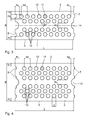
- the in FIG. 1 brick shown has nineteen Dämmö réelleen 10 in two rows with a diameter of 45 mm.
- the distance a 3 to the inside 1 is significantly greater than the distance a 1 to the outside 2.
- the insulating openings 10 are arranged in the heat transmission direction 9 in the vicinity of the outside 2, wherein the row oriented with ten Dämmö réelleen 10 closer to the outside 2 is as the series with nine Dämmö réelleen 10. According to this arrangement, the brick seventeen node 12 on.
- the arrangement of the insulating openings 10 in the brick according to FIG. 2 is similar to that in the brick according to FIG. 1 , wherein a third row of eight Dämmö Maschinenen 10 on the inner side 1 facing side of the row is supplemented with the nine Dämmö réelleen 10, so that a total of twenty-seven Dämmö réelleen 10 are present. Through the third row Dämmö Maschinenen 10 more fifteen nodes 12 are created so that this brick comprises a total of thirty-two nodes 12.
- the rows of Dämmö réelleen 10 are overall in the embodiment according to Fig. 1 and 2 positioned in the side of the brick facing the outside 2 of the brick, that the rows of insulating holes 10 are arranged in a thickness zone Z a , which extends to the outside 2 beyond the longitudinal center plane LM of the brick.
- the stone is due to the undisturbed by openings inner layer Z i statically particularly viable, but met by the Dämmein accounts 11 high demands on the insulating ability.
- grid center distance a R within a row 58 mm, the row spacing d R is set at 5 mm. This results in the grid center distance a R for adjacent dam openings 10 between two adjacent rows of 57.8 mm, so that substantially a uniform grid center distance a R is created between two adjacent dam openings 10 within a row and over two rows.
- the brick according to Fig. 3 has a total of thirty-four insulating apertures 10 with a diameter of 40 mm, which are arranged in pairs in two identical series groups. In each case a row with nine Dämmö réelleen is arranged from the inside 1 and the outer side 2 of the brick with a distance a 1 and a 3 of 35 mm. The rows with eight dam openings are oriented to the brick interior, opposite each other. The distance between the row groups d G is 50 mm. Overall, one results in a symmetry plane fourteen symmetrical arrangement of the insulating openings 10 on the top surface. 3
- the raster pitch a R within a row is 63.4 mm, with the row spacing d R being set at 10 mm. This results in the grid center distance a R for adjacent Dämmö réelleen 10 between two adjacent rows of 59.2 mm.
- the brick according to Fig. 3 has a total of thirty-two nodes 12.
- the arrangement of the insulating openings 10 in the brick according to FIG. 4 is similar to that in the brick according to FIG. 3 , wherein a third row of eight Dämmö Maschinenen 10 connects to the row with the nine Dämmö réelleen 10, so that twenty-five Dämmö réelleen 10 per row group and a total of fifty Dämmö réelleen 10 are present. By the third row of the Dämmötechnischen 10 more thirty-two nodes 12 are created so that this brick comprises a total of sixty-four nodes 12.
- the arrangement of the insulating openings 10 in the brick according to FIG. 5 is also similar to that in the brick according to FIG. 3 , wherein a total of twenty-six Dämmö réelleen 10 are provided with a diameter of 50 mm.
- the two outer rows each have seven Dämmö réelleen 10 and two inner rows, which are arranged with a distance between the row groups d G of 75 mm, each have six Dämmötechnischen 10.
- the raster pitch a R within a row is 82.8 mm, with the row spacing d R being set at 5 mm. This results in the grid center distance a R for adjacent Dämmö réelleen 10 between two adjacent rows of 68.9 mm.
- the brick according to Fig. 4 has a total of twenty-four nodes 12.
- the arrangement of the insulating openings 10 in the brick according to FIG. 6 is similar to that in the brick according to FIG. 5 , wherein a third row of six Dämmö Maschinenen 10 connected to the series with the seven Dämmö Maschinenen 10, so that there are nineteen Dämmö réelleen 10 per row group and a total of thirty-eight Dämmö réelleen 10. Through the third row of Dämmö Maschinenen 10 are another twenty four Node 12 is created so that this brick comprises a total of forty eight knots 12.
- the following dimension table gives the concrete dimensions of the bricks shown FIGS. 1 to 6 at. dimension table Fig. 1 Fig. 2 Fig. 3 Fig. 4 Fig. 5 Fig. 6 L in mm 624 624 624 624 624 624 B in mm 300 365 300 400 365 500 d in mm 45 45 40 40 50 50 a 1 in mm 30 30 35 35 40 52.5 a 2 in mm 21 21 30 30 30 30 30 a 3 in mm 175 190 35 35 40 52.5 a 4 in mm 36 36 47 47 47 47 F in mm 2 1831 2236 1831 2452 2236 3075 D in mm 2 302 429 427 628 510 746
- the thermal conductivity ⁇ which is 0.09 W / mK for a classic porous concrete brick to 0.079 W / mK for the brick according to FIG. 1 and to 0.076 W / mK for the brick according to FIG. 2 is reduced.
- This follows, in particular, from the increase in the sum-insulating area of 302 mm 2 in the first exemplary embodiment 429 mm 2 in the second embodiment, so that the insulation effect is further improved.
- This is not only an improved thermal insulation compared to the known aerated concrete brick but also against a porous concrete brick type YTONG, which has a thermal conductivity of 0.08 W / mK.
- the improvement of the thermal insulation compared to the YTONG brick is low, but the brick according to the invention is also superior due to its increased mechanical strength.
Landscapes
- Engineering & Computer Science (AREA)
- Architecture (AREA)
- Civil Engineering (AREA)
- Structural Engineering (AREA)
- Building Environments (AREA)
Abstract
Description
- Die Erfindung betrifft einen Mauerstein aus Porenbeton.
- Derartige Mauersteine sind grundsätzlich seit langem bekannt. Sie zeichnen sich durch einen materialeinheitlichen Aufbau aus einem tragendem Betonmaterial aus, das mit in der Regel feinen Poren innig durchsetzt ist. Durch diese Lufteinschlüsse weist ein solcher Porenbetonstein bereits an sich ein gutes Wärmedämmvermögen auf.
- An Mauerbaustoffe, insbesondere für den Wohnungsbau, werden nun zunehmend anspruchsvollere Anforderungen gestellt. So soll die klassische massive Bauweise mit einer hohen Belastbarkeit des Mauerwerks und einem ausgezeichneten Brand- und Lärmschutzverhalten bei möglichst geringen Wanddicken realisierbar sein. Dabei soll eine möglichst hohe Wärmedämmung erreicht werden. Optimalerweise soll der Wärmedurchgang durch die Wand so niedrig gehalten werden, dass hohe Standards, wie sie beispielsweise für den Bau eines sogenannten Passivhauses gefordert werden, eingehalten sind.
- Durch offenkundige Vorbenutzung sind Mauersteine aus Porenbeton mit zusätzlichen Dämmeinsätzen zur Erhöhung der Dämmwirkung bekannt. Derartige Mauersteine weisen eine reduzierte Belastbarkeit des Mauerwerks auf.
- Davon ausgehend liegt der Erfindung die Ausgabe zugrunde, einen Mauerstein aus Porenbeton derart zu gestalten, dass eine hohe Belastbarkeit des Mauerwerks bei gleichzeitig möglichst hoher Wärmedämmung gewährleistet ist.
- Diese Aufgabe wird durch einen Porenbeton-Mauerstein mit den im Anspruch 1 angegebenen Merkmalen gelöst.
- Demnach wird eine verbesserte Wärmedämmung gegenüber einem herkömmlichen Mauerstein aus Porenbeton dadurch erreicht, dass in dem Mauerstein mehrere quer zu einer Wärmedurchgangsrichtung verlaufende Reihen vertikaler Dämmöffnungen vorgesehen sind, in die Dämmeinsätze aus Wärmedämmmaterial eingesetzt werden. Dadurch, dass sowohl die Dämmöffnungen als auch die Dämmeinsätze zylindrisch und in benachbarten Reihen versetzt zueinander angeordnet sind, entsteht eine wabenförmige Struktur in dem Mauerstein. Diese Struktur zeichnet sich durch eine Vielzahl von regelmäßig angeordneten Knoten aus, mittels derer der Porenbeton-Mauerstein einer hohen Mauerdruckspannung standhält, da Spannungsspitzen einer mechanischen Belastung des Mauersteins in Folge von Kerbwirkung hervorgerufen durch eine sprunghafte Querschnittsänderung oder scharfe Ecken und Kanten vermieden werden. Die Verwendung von Dämmeinsätzen in einem Mauerstein ist zwar bereits aus der Ziegelindustrie bekannt, jedoch werden dort quaderförmige Einsätze verwendet, die aufgrund ihrer Anordnung im Mauerstein im Belastungsfall eine ungünstige Beanspruchung des Mauerwerks hervorrufen und damit insgesamt die Belastbarkeit des Mauerwerks reduzieren.
- In den abhängigen Ansprüchen sind bevorzugte Ausführungsformen des Mauersteins angegeben. Deren Merkmale, Einzelheiten und Vorteile werden aus der nachfolgenden Beschreibung anhand der beigefügten Zeichnung klar. Es zeigen:
- Fig. 1 bis 6
- Draufsichten auf Mauersteine in unterschiedlichen Ausführungsformen.
- Der in den Figuren dargestellte Mauerstein besteht aus üblichem Porenbeton und ist in seinem Grundaufbau quaderförmig mit einer Innenseite 1, einer Außenseite 2, einer nicht erkennbaren Grundfläche, einer Deckfläche 3 und den beiden seitlichen Fugenflächen 4, 5. Letztere sind mittig mit einer vertikal durchgehenden, im Horizontalschnitt halbkreisförmigen Mörtelnut 6, sowie einem nut- und federartigen Passsystem mit im Horizontalschnitt trapezförmigen, vertikal durchgehenden Stegvorsprüngen 7 und korrespondierenden Ausnehmungen 8 versehen.
- Quer zu einer Wärmedurchgangsrichtung 9 sind mehrere Reihen vertikaler Durchgangsbohrungen 10 angeordnet, in die jeweils ein Dämmeinsatz 11 aus Mineralfaser eingesetzt ist. Aus Darstellungsgründen sind in den Figuren auch Dämmöffnungen 10 ohne Dämmeinsatz 11 gezeigt, wobei bei dem erfindungsgemäßen Mauerstein alle Dämmöffnungen 10 einen korrespondierenden Dämmeinsatz 11 aufweisen. Die Dämmöffnungen sind zylindrisch und haben einen Durchmesser d in einem Bereich von 40 mm bis 50 mm, wobei auch Durchmesser von 30 mm bis 60 mm denkbar sind.
- Aus den Figuren ist weiterhin zu erkennen, dass die Dämmöffnungen 10 benachbarter Reihen derart versetzt zueinander angeordnet sind, dass ein gleichmäßiger Rastermittenabstand aR zwischen zwei benachbarten Dämmöffnungen 10 in einer Reihe und im Wesentlichen auch zwischen zwei benachbarten Reihen vorliegt. Die Dämmöffnungen 10 sind in dem gleichmäßigen Rastermittenabstand aR von 50 mm bis 85 mm angeordnet. Weiterhin beträgt ein Reihenabstand dR der Dämmöffnungen 10 zwischen zwei benachbarten Reihen 3 mm bis 15 mm. Es ist auch denkbar, den Reihenabstand dR derart festzulegen, dass der Rastermittenabstand aR für alle benachbarten Dämmöffnungen 10 identisch ist. Dadurch ergibt sich eine gleichmäßige Anordnung der Dämmöffnungen 10, die durch Verbindungsstege 13 miteinander verbundene Knoten 12 einschließen. Durch diese wabenförmige Struktur der Dämmöffnungen 10 mit den dazwischen angeordneten Knoten 12 wird ein Mauerstein mit einer hohen Belastbarkeit geschaffen.
- Der Dämmeinsatz 11 ist stabförmig und korrespondierend zu der als Durchgangsbohrung gestalteten Dämmöffnung 10 ausgebildet, sodass die Dämmöffnung 10 durch den eingesetzten Dämmeinsatz 11 vollständig ausgefüllt ist. Der Dämmeinsatz 11 ist aus Wärmedämmmaterial, insbesondere Mineralfasermaterial in Form von Mineralfaserplatten, insbesondere Steinwolleplatten mit einer Wärmeleitfähigkeit λ = 0,035 W/mK, hergestellt. Es können aber auch andere Wärmedämmmaterialien verwendet werden.
- Der Mauerstein weist bei beiden Ausführungsformen eine Länge L von 624 mm auf, eine Breite B variiert bei den Ausführungsformen. Die wabenförmige Struktur der Dämmöffnungen 10 ist zu den Fugenflächen 4, 5, der Innenseite 1 und der Außenseite 2 in Abständen a1 bis a4 angeordnet. Zwischen den Dämmöffnungen 10 und der Außenseite 2 ist eine äußere Bewitterungszone mit einer Breite, die dem Abstand a1 entspricht, vorgesehen, um den Mauerstein auf der Außenseite ausreichend, insbesondere gegen Witterungseinflüsse, zu schützen. Die Abstände a2 und a4 zu den Fugenflächen 4, 5 sind im Wesentlichen gleich groß, sodass die Dämmöffnungen 10 in einer Richtung senkrecht zur Wärmedurchgangsrichtung 9 in etwa zentriert angeordnet sind.
- Die Deckfläche 3 hat einen Flächeninhalt F, die Summe der Einzel-Querschnittsflächen der Dämmöffnungen 11 ergibt eine Summen-Dämmfläche D.
- Der in
Figur 1 gezeigte Mauerstein weist neunzehn Dämmöffnungen 10 in zwei Reihen mit einem Durchmesser von 45 mm auf. Der Abstand a3 zur Innenseite 1 ist dabei deutlich größer als der Abstand a1 zur Außenseite 2. Also sind die Dämmöffnungen 10 in der Wärmedurchgangsrichtung 9 in der Nähe der Außenseite 2 angeordnet, wobei die Reihe mit zehn Dämmöffnungen 10 näher an der Außenseite 2 orientiert ist als die Reihe mit neun Dämmöffnungen 10. Gemäß dieser Anordnung weist der Mauerstein siebzehn Knoten 12 auf. - Die Anordnung der Dämmöffnungen 10 in dem Mauerstein gemäß
Figur 2 ist ähnlich der in dem Mauerstein gemäßFigur 1 , wobei eine dritte Reihe von acht Dämmöffnungen 10 auf der der Innenseite 1 zugewandten Seite der Reihe mit den neun Dämmöffnungen 10 ergänzt ist, sodass insgesamt siebenundzwanzig Dämmöffnungen 10 vorliegen. Durch die dritte Reihe Dämmöffnungen 10 werden weitere fünfzehn Knoten 12 geschaffen, sodass dieser Mauerstein insgesamt zweiunddreißig Knoten 12 umfasst. - Die Reihen von Dämmöffnungen 10 sind insgesamt bei der Ausführungsform gemäß
Fig. 1 und 2 so in der zur Außenseite 2 des Mauersteins hin gelegenen Seite des Mauersteins positioniert, dass die Reihen von Dämmöffnungen 10 in einer Dickenzone Za angeordnet ist, die sich zur Außenseite 2 jenseits der Längsmittelebene LM des Mauersteins erstreckt. Damit ist der Stein aufgrund der durch Öffnungen ungestörten inneren Lage Zi statisch besonders tragfähig, erfüllt allerdings durch die Dämmeinsätze 11 hohe Anforderungen an die Dämmfähigkeit. - Für die in den
Figuren 1 und 2 dargestellten Ausführungsformen beträgt Rastermittenabstand aR innerhalb einer Reihe 58 mm, wobei der Reihenabstand dR mit 5 mm festgelegt ist. Daraus folgt der Rastermittenabstand aR für benachbarte Dämmöffnungen 10 zwischen zwei benachbarten Reihen von 57,8 mm, so dass im Wesentlichen ein einheitlicher Rastermittenabstand aR zwischen zwei benachbarten Dämmöffnungen 10 innerhalb einer Reihe und über zwei Reihen hinweg geschaffen ist. - Der Mauerstein gemäß
Fig. 3 weist insgesamt vierunddreißig Dämmöffnungen 10 mit einem Durchmesser von 40 mm auf, die paarweise in zwei identischen Reihengruppen angeordnet sind. Jeweils eine Reihe mit neun Dämmöffnungen ist von der Innenseite 1 bzw. der Außenseite 2 des Mauersteins mit einem Abstand a1 bzw. a3 von 35 mm angeordnet. Die Reihen mit acht Dämmöffnungen sind zum Mauersteininneren, einander gegenüberliegend orientiert. Der Abstand zwischen den Reihengruppen dG beträgt 50 mm. Insgesamt resultiert eine zu einer Symmetrieebene vierzehn symmetrische Anordnung der Dämmöffnungen 10 auf der Deckfläche 3. - Der Rastermittenabstand aR innerhalb einer Reihe beträgt 63,4 mm, wobei der Reihenabstand dR mit 10 mm festgelegt ist. Daraus folgt der Rastermittenabstand aR für benachbarte Dämmöffnungen 10 zwischen zwei benachbarten Reihen von 59,2 mm. Der Mauerstein gemäß
Fig. 3 weist insgesamt zweiunddreißig Knoten 12 auf. - Die Anordnung der Dämmöffnungen 10 in dem Mauerstein gemäß
Figur 4 ist ähnlich der in dem Mauerstein gemäßFigur 3 , wobei sich eine dritte Reihe von acht Dämmöffnungen 10 an die Reihe mit den neun Dämmöffnungen 10 anschließt, so dass fünfundzwanzig Dämmöffnungen 10 je Reihengruppe und insgesamt fünfzig Dämmöffnungen 10 vorliegen. Durch die dritte Reihe der Dämmöffnungen 10 werden weitere zweiunddreißig Knoten 12 geschaffen, so dass dieser Mauerstein insgesamt vierundsechzig Knoten 12 umfasst. - Weiterhin weist der Mauerstein gemäß
Fig. 4 zwei zusätzliche, identisch ausgebildete Stegvorsprünge 7 sowie dazu korrespondierende Ausnehmungen 8 auf. - Die Anordnung der Dämmöffnungen 10 in dem Mauerstein gemäß
Figur 5 ist ebenfalls ähnlich der in dem Mauerstein gemäßFigur 3 , wobei insgesamt sechsundzwanzig Dämmöffnungen 10 mit einem Durchmesser von 50 mm vorgesehen sind. Die zwei äußeren Reihen weisen jeweils sieben Dämmöffnungen 10 und zwei inneren Reihen, die mit einem Abstand zwischen den Reihengruppen dG von 75 mm angeordnet sind, weisen jeweils sechs Dämmöffnungen 10 auf. - Der Rastermittenabstand aR innerhalb einer Reihe beträgt 82,8 mm, wobei der Reihenabstand dR mit 5 mm festgelegt ist. Daraus folgt der Rastermittenabstand aR für benachbarte Dämmöffnungen 10 zwischen zwei benachbarten Reihen von 68,9 mm. Der Mauerstein gemäß
Fig. 4 weist insgesamt vierundzwanzig Knoten 12 auf. - Die Anordnung der Dämmöffnungen 10 in dem Mauerstein gemäß
Figur 6 ist ähnlich der in dem Mauerstein gemäßFigur 5 , wobei sich eine dritte Reihe von sechs Dämmöffnungen 10 an die Reihe mit den sieben Dämmöffnungen 10 anschließt, so dass neunzehn Dämmöffnungen 10 je Reihengruppe und insgesamt achtunddreißig Dämmöffnungen 10 vorliegen. Durch die dritte Reihe der Dämmöffnungen 10 werden weitere vierundzwanzig Knoten 12 geschaffen, so dass dieser Mauerstein insgesamt achtundvierzig Knoten 12 umfasst. - Weiterhin weist der Mauerstein gemäß
Fig. 6 analog zu dem gemäßFig. 4 zwei zusätzliche Stegvorsprünge 7 sowie dazu korrespondierende Ausnehmungen 8 auf. - Die folgende Dimensionstabelle gibt die konkreten Maße der gezeigten Mauersteine gemäß
Figuren 1 bis 6 an.
DimensionstabelleFig. 1 Fig. 2 Fig. 3 Fig. 4 Fig. 5 Fig. 6 L in mm 624 624 624 624 624 624 B in mm 300 365 300 400 365 500 d in mm 45 45 40 40 50 50 a1 in mm 30 30 35 35 40 52,5 a2 in mm 21 21 30 30 30 30 a3 in mm 175 190 35 35 40 52,5 a4 in mm 36 36 47 47 47 47 F in mm2 1831 2236 1831 2452 2236 3075 D in mm2 302 429 427 628 510 746 - Aufgrund der erfindungsgemäßen Verwendung der Dämmeinsätze 11 in den Dämmöffnungen 10 wird die Wärmeleitfähigkeit λ, die für einen klassischen Porenbeton-Mauerstein 0,09 W/mK beträgt, auf 0,079 W/mK für den Mauerstein gemäß
Figur 1 und auf 0,076 W/mK für den Mauerstein gemäßFigur 2 reduziert wird. Dies folgt vor allem aus der Erhöhung der Summen-Dämmfläche von 302 mm2 im ersten Ausführungsbeispiel auf 429 mm2 im zweiten Ausführungsbeispiel, sodass die Dämmwirkung zusätzlich verbessert wird. Damit wird nicht nur eine verbesserte Wärmedämmung gegenüber dem bekannten Porenbeton-Mauerstein sondern auch gegenüber einem Porenbeton-Mauerstein vom Typ YTONG, der eine Wärmeleitfähigkeit von 0,08 W/mK aufweist. Zwar ist die Verbesserung der Wärmedämmung gegenüber dem YTONG-Mauerstein nur gering, jedoch ist der erfindungsgemäße Mauerstein aufgrund seiner erhöhten mechanischen Belastbarkeit zusätzlich überlegen.
Claims (11)
- Mauerstein aus Porenbeton umfassend- mehrere quer zu einer Wärmedurchgangsrichtung (9) verlaufende Reihen vertikaler Dämmöffnungen (10) und- jeweils in die Dämmöffnungen (10) eingesetzte Dämmeinsätze (11) aus einem Wärmedämmmaterial,wobei die Dämmöffnungen (10) benachbarter Reihen versetzt zueinander angeordnet sind,
dadurch gekennzeichnet, dass
die Dämmöffnungen (10) und die jeweils darin befindlichen Dämmeinsätze (11) zylindrisch geformt sind. - Mauerstein nach Anspruch 1, dadurch gekennzeichnet, dass die Dämmöffnungen (10) einen Durchmesser (d) von 30 mm bis 60 mm, insbesondere von 35 mm bis 55 mm, aufweisen.
- Mauerstein nach einem der vorgenannten Ansprüche, dadurch gekennzeichnet, dass die Dämmöffnungen (10) in einem gleichmäßigen Rastermittenabstand (aR) in einer Reihe angeordnet sind.
- Mauerstein nach Anspruch 3, gekennzeichnet durch einen Rastermittenabstand (aR) von 50 mm bis 85 mm.
- Mauerstein nach einem der vorgenannten Ansprüche, dadurch gekennzeichnet, dass ein Reihenabstand (dR) der Dämmöffnungen (10) zwischen zwei benachbarten Reihen 3 mm bis 15 mm beträgt.
- Mauerstein nach einem der Ansprüche 3 bis 5, gekennzeichnet durch den Reihenabstand (dR) derart, dass alle benachbarten Dämmöffnungen (10) im gleichmäßigen Rastermittenabstand (aR) angeordnet sind.
- Mauerstein nach einem der vorgenannten Ansprüche, gekennzeichnet durch eine bezüglich einer Symmetrieebene (14) des Mauersteins symmetrische Anordnung der Dämmöffnungen (10).
- Mauerstein nach einem der Ansprüche 1 bis 7, dadurch gekennzeichnet, dass mehrere Reihen von Dämmöffnungen (10) in der zur Außenseite (2) des Mauersteins hin gelegenen Seite des Mauersteins mit einem Abstand (a3) zur Innenseite (1) angeordnet sind, der deutlich größer als der Abstand (a1) zur Außenseite ist.
- Mauerstein nach Anspruch 8, dadurch gekennzeichnet, dass die mehreren Reihen von Dämmöffnungen (10) in einer Dickenzone (Za) angeordnet ist, die sich zur Außenseite (2) jenseits der Längsmittelebene (LM) des Mauersteins erstreckt.
- Mauerstein nach einem der vorgenannten Ansprüche, dadurch gekennzeichnet, dass die Dämmöffnungen (10) Durchgangsbohrungen sind.
- Mauerstein nach einem der vorgenannten Ansprüche, dadurch gekennzeichnet, dass das Wärmedämmmaterial ein Mineralfasermaterial, insbesondere Steinwolle ist.
Applications Claiming Priority (1)
| Application Number | Priority Date | Filing Date | Title |
|---|---|---|---|
| DE102009011992A DE102009011992A1 (de) | 2009-03-05 | 2009-03-05 | Mauerstein aus Porenbeton |
Publications (2)
| Publication Number | Publication Date |
|---|---|
| EP2226445A2 true EP2226445A2 (de) | 2010-09-08 |
| EP2226445A3 EP2226445A3 (de) | 2013-10-09 |
Family
ID=42309522
Family Applications (1)
| Application Number | Title | Priority Date | Filing Date |
|---|---|---|---|
| EP10155531.6A Withdrawn EP2226445A3 (de) | 2009-03-05 | 2010-03-04 | Mauerstein aus Porenbeton |
Country Status (2)
| Country | Link |
|---|---|
| EP (1) | EP2226445A3 (de) |
| DE (2) | DE102009011992A1 (de) |
Family Cites Families (6)
| Publication number | Priority date | Publication date | Assignee | Title |
|---|---|---|---|---|
| DE1771853B1 (de) * | 1968-07-20 | 1971-11-25 | Heinz Dennert | Aussenwandstein mit Waermedaemmung |
| EP0045047B1 (de) * | 1980-07-25 | 1985-07-17 | Adams, EngelbertIng.VDI | Verfahren und Vorrichtung zur Herstellung eines wärmedämmenden Hohlblocksteins |
| DE3216080A1 (de) * | 1982-04-30 | 1983-11-03 | Paul Dahm Bimsbaustoffwerke, 5450 Neuwied | Hohlblockstein |
| DE4432387A1 (de) * | 1993-07-23 | 1996-03-14 | Hans Herberger | Bauelement |
| DE212004000002U1 (de) * | 2003-03-07 | 2005-01-20 | Roitmair, Helmut | Bausteinverbund |
| DE102007024380B4 (de) * | 2007-05-23 | 2009-02-26 | Ziegelwerk Bellenberg Wiest Gmbh & Co. Kg | Verfahren zum Herstellen eines Formsteins und Formsteinfüllvorrichtung |
-
2009
- 2009-03-05 DE DE102009011992A patent/DE102009011992A1/de not_active Withdrawn
-
2010
- 2010-03-04 EP EP10155531.6A patent/EP2226445A3/de not_active Withdrawn
- 2010-03-04 DE DE202010018146.1U patent/DE202010018146U1/de not_active Expired - Lifetime
Non-Patent Citations (1)
| Title |
|---|
| None |
Also Published As
| Publication number | Publication date |
|---|---|
| EP2226445A3 (de) | 2013-10-09 |
| DE202010018146U1 (de) | 2014-05-15 |
| DE102009011992A1 (de) | 2010-09-09 |
Similar Documents
| Publication | Publication Date | Title |
|---|---|---|
| DE3901897A1 (de) | Gummifederelement | |
| DE102007061451A1 (de) | Hochlochziegel | |
| AT524923B1 (de) | Profilelement | |
| EP3385462A1 (de) | Thermisch isolierendes bauelement | |
| DE1708765B1 (de) | Hohlblockstein | |
| EP2208833B1 (de) | Mauerstein aus Porenbeton | |
| EP2080845B1 (de) | Holzfertigbauelement | |
| DE69709803T2 (de) | Lochziegel | |
| DE102012008771A1 (de) | Modul aus verleimten Massivholzlamellenstäben zur Herstellung von Einrichtungsgegenständen oder Bauteilen | |
| DE202010018146U1 (de) | Mauerstein aus Porenbeton | |
| EP0606625B1 (de) | Hintermauerziegel | |
| AT520195B1 (de) | Dämmmaterialfreier Hochlochziegel mit tragender Lamellenstruktur zur Gebäudekonstruktion | |
| EP2092132B1 (de) | Strukturteil für holzbauten | |
| DE202007016864U1 (de) | Mauerstein | |
| DE1484213C3 (de) | ||
| DE102015122919A1 (de) | Holzmauerstein | |
| DE3023238C2 (de) | Anordnung der Heizelemente in einem elektrisch beheizten Ofen mit stabförmigen Heizelementen | |
| DE3030846A1 (de) | Hochlochziegel | |
| DE3615247C2 (de) | ||
| DE806482C (de) | Mauer aus in Abstand voneinander stehenden, durch Bauplatten gebildeten Schichten | |
| AT309759B (de) | Hohlblockstein | |
| DE866382C (de) | Baustein und Bausteinanordnung | |
| DE19804729A1 (de) | Baustein, insbesondere auf der Basis zementgebundenen Blähtons | |
| EP1428954A1 (de) | Leicht-Hochlochziegel | |
| DE202012007558U1 (de) | Mauerstein |
Legal Events
| Date | Code | Title | Description |
|---|---|---|---|
| PUAI | Public reference made under article 153(3) epc to a published international application that has entered the european phase |
Free format text: ORIGINAL CODE: 0009012 |
|
| AK | Designated contracting states |
Kind code of ref document: A2 Designated state(s): AT BE BG CH CY CZ DE DK EE ES FI FR GB GR HR HU IE IS IT LI LT LU LV MC MK MT NL NO PL PT RO SE SI SK SM TR |
|
| AX | Request for extension of the european patent |
Extension state: AL BA ME RS |
|
| PUAL | Search report despatched |
Free format text: ORIGINAL CODE: 0009013 |
|
| AK | Designated contracting states |
Kind code of ref document: A3 Designated state(s): AT BE BG CH CY CZ DE DK EE ES FI FR GB GR HR HU IE IS IT LI LT LU LV MC MK MT NL NO PL PT RO SE SI SK SM TR |
|
| AX | Request for extension of the european patent |
Extension state: AL BA ME RS |
|
| RIC1 | Information provided on ipc code assigned before grant |
Ipc: E04B 2/16 20060101AFI20130904BHEP |
|
| STAA | Information on the status of an ep patent application or granted ep patent |
Free format text: STATUS: THE APPLICATION IS DEEMED TO BE WITHDRAWN |
|
| 18D | Application deemed to be withdrawn |
Effective date: 20140410 |