EP2227636B1 - Pompe aspirante à membrane à plusieurs étages - Google Patents
Pompe aspirante à membrane à plusieurs étages Download PDFInfo
- Publication number
- EP2227636B1 EP2227636B1 EP20080853296 EP08853296A EP2227636B1 EP 2227636 B1 EP2227636 B1 EP 2227636B1 EP 20080853296 EP20080853296 EP 20080853296 EP 08853296 A EP08853296 A EP 08853296A EP 2227636 B1 EP2227636 B1 EP 2227636B1
- Authority
- EP
- European Patent Office
- Prior art keywords
- pump
- line
- valve
- valves
- inlet
- Prior art date
- Legal status (The legal status is an assumption and is not a legal conclusion. Google has not performed a legal analysis and makes no representation as to the accuracy of the status listed.)
- Active
Links
Images


Classifications
-
- F—MECHANICAL ENGINEERING; LIGHTING; HEATING; WEAPONS; BLASTING
- F04—POSITIVE - DISPLACEMENT MACHINES FOR LIQUIDS; PUMPS FOR LIQUIDS OR ELASTIC FLUIDS
- F04B—POSITIVE-DISPLACEMENT MACHINES FOR LIQUIDS; PUMPS
- F04B45/00—Pumps or pumping installations having flexible working members and specially adapted for elastic fluids
- F04B45/04—Pumps or pumping installations having flexible working members and specially adapted for elastic fluids having plate-like flexible members, e.g. diaphragms
- F04B45/043—Pumps or pumping installations having flexible working members and specially adapted for elastic fluids having plate-like flexible members, e.g. diaphragms two or more plate-like pumping flexible members in parallel
-
- F—MECHANICAL ENGINEERING; LIGHTING; HEATING; WEAPONS; BLASTING
- F04—POSITIVE - DISPLACEMENT MACHINES FOR LIQUIDS; PUMPS FOR LIQUIDS OR ELASTIC FLUIDS
- F04B—POSITIVE-DISPLACEMENT MACHINES FOR LIQUIDS; PUMPS
- F04B25/00—Multi-stage pumps
-
- F—MECHANICAL ENGINEERING; LIGHTING; HEATING; WEAPONS; BLASTING
- F04—POSITIVE - DISPLACEMENT MACHINES FOR LIQUIDS; PUMPS FOR LIQUIDS OR ELASTIC FLUIDS
- F04B—POSITIVE-DISPLACEMENT MACHINES FOR LIQUIDS; PUMPS
- F04B37/00—Pumps having pertinent characteristics not provided for in, or of interest apart from, groups F04B25/00 - F04B35/00
- F04B37/10—Pumps having pertinent characteristics not provided for in, or of interest apart from, groups F04B25/00 - F04B35/00 for special use
- F04B37/14—Pumps having pertinent characteristics not provided for in, or of interest apart from, groups F04B25/00 - F04B35/00 for special use to obtain high vacuum
-
- F—MECHANICAL ENGINEERING; LIGHTING; HEATING; WEAPONS; BLASTING
- F04—POSITIVE - DISPLACEMENT MACHINES FOR LIQUIDS; PUMPS FOR LIQUIDS OR ELASTIC FLUIDS
- F04B—POSITIVE-DISPLACEMENT MACHINES FOR LIQUIDS; PUMPS
- F04B41/00—Pumping installations or systems specially adapted for elastic fluids
- F04B41/06—Combinations of two or more pumps
-
- F—MECHANICAL ENGINEERING; LIGHTING; HEATING; WEAPONS; BLASTING
- F04—POSITIVE - DISPLACEMENT MACHINES FOR LIQUIDS; PUMPS FOR LIQUIDS OR ELASTIC FLUIDS
- F04B—POSITIVE-DISPLACEMENT MACHINES FOR LIQUIDS; PUMPS
- F04B49/00—Control, e.g. of pump delivery, or pump pressure of, or safety measures for, machines, pumps, or pumping installations, not otherwise provided for, or of interest apart from, groups F04B1/00 - F04B47/00
- F04B49/007—Installations or systems with two or more pumps or pump cylinders, wherein the flow-path through the stages can be changed, e.g. from series to parallel
-
- Y—GENERAL TAGGING OF NEW TECHNOLOGICAL DEVELOPMENTS; GENERAL TAGGING OF CROSS-SECTIONAL TECHNOLOGIES SPANNING OVER SEVERAL SECTIONS OF THE IPC; TECHNICAL SUBJECTS COVERED BY FORMER USPC CROSS-REFERENCE ART COLLECTIONS [XRACs] AND DIGESTS
- Y10—TECHNICAL SUBJECTS COVERED BY FORMER USPC
- Y10T—TECHNICAL SUBJECTS COVERED BY FORMER US CLASSIFICATION
- Y10T137/00—Fluid handling
- Y10T137/8593—Systems
- Y10T137/85978—With pump
- Y10T137/86131—Plural
- Y10T137/86139—Serial
Definitions
- the invention relates to a multi-stage membrane suction pump having at least two pump chambers, each having a, at least one inlet valve having fluid inlet and a, at least one outlet valve having fluid outlet, and with a, the fluid inlets of the pumping chambers connecting suction line, each successive pumping spaces each at least a connecting line are connected to each other such that the diaphragm pump on reaching / exceeding a differential pressure in the suction line of a parallel operating operation of their pumping chambers in at least also serially operating operation of these pumping rooms, wherein in the inflow and outflow of the at least one connecting line at least one , the check valve opening to the subsequent pumping stage is interposed, and wherein the check valves provided in the inflow and outflow region of the connecting line (s) in comparison with the inlet and outlet v Are made of the pumping spaces smaller.
- micro-vacuum pump that holds two, each by an oscillating pumping diaphragm limited pumping spaces.
- Each of these pump rooms has one, an inlet valve having fluid inlet and a, an outlet valve exhibiting fluid outlet, wherein a suction line connecting the fluid inlets of the pumping chambers and a, the fluid outlets connecting pressure line is provided.
- the pump chambers are connected to one another via a connecting line in such a way that the previously known micro-vacuum pump, upon reaching and exceeding a defined differential pressure in the suction line, transitions from a parallel operating operation of its pumping chambers into a series-operating operation of these pumping chambers.
- a check valve which opens for the subsequent pumping stage is interposed in each case.
- the check valves interposed in the connecting line have a size comparable to the inlet and outlet valves of the two pumping chambers. Accordingly, the line section of the connecting line provided between one of the check valves, on the one hand, and the adjacent pump chamber, on the other hand, is dimensioned comparably large.
- a throttle is interposed in the connecting line, which loses its throttling effect only when a corresponding pressure difference and a reduced pumping capacity are reached.
- the previously known micro-vacuum pump adopts a parallel configuration of its pumping chambers, because the throttle provided in the connecting line causes the system to be able to initially work more easily in parallel due to the still lacking obstructions in the air circulation.
- the fluid can much easier flow through the throttle located in the connecting line, so that it is also configured in a serial operation of their pumping rooms, now to To achieve the highest possible ultimate vacuum.
- an at least two-stage superheated steam vacuum pump which has push-pull membranes as pumping members.
- the inlets and outlets of the pump chambers of this multi-stage hot steam vacuum pump are connected in parallel via lines.
- a control line connecting the pumping chambers is provided which has a check valve arrangement with one control valve arranged at the beginning and at the end of the control line.
- the two stages of the pump work in parallel, because the control line is shut off by the vacuum control valves. From a certain pressure difference opens the vacuum control valves and the two pumps operate substantially in series.
- the valve members of the control valves provided in the control line at least 30% lower mass than the valve members of the provided in the pump inlet and in the pump outlet check valves.
- a valve-controlled operating mode control for multi-stage gas feed pumps.
- the known operating mode control which comprises the combination of two check valves and an overpressure and / or a diaphragm-controlled vacuum valve
- an automatic switching of the operating mode is accomplished by opening the overpressure or diaphragm-controlled vacuum valve when a defined pressure or vacuum is reached. Close the check valves and the volume flow is passed from the pressure side of a pumping stage in the suction side of another pumping stage. Thus, the pump stages are shifted from parallel to serial mode.
- the inventive solution to this problem is in particular in that the non-return valves provided in the inflow and outflow regions of the connecting line (s) are each assigned a line section of the connecting line open to the adjacent pumping chamber with a smaller line cross section than the inlet and outlet valves, and in that between the first and the last pump stage of the membrane suction pump remaining or middle pumping stages each open at least one inlet, one outlet and two check valves.
- the membrane suction pump according to the invention which has at least one middle pumping stage between the first and the last pumping stage, is configured at least in three stages. While at the out DE 10 2006 043 159 B3 Prior art hot steam vacuum pump only at the beginning and at the end of the control line, a negative pressure control valve is to be provided in the membrane suction pump according to the invention in each provided between the pumping stages connecting line inflow and outflow side each provided a check valve. In order to further reduce the harmful space, it is provided according to the invention that at least one inlet, one outlet and two check valves each open into the pump stages remaining between the first and the last pump stage of the membrane suction pump.
- the membrane pump according to the invention has both in the at least one connecting line connecting their pumping spaces inflow as well as outflow check valves, which are dimensioned much smaller compared to the inlet and outlet valves of these pump chambers. Since the movable valve body of these check valves thus also have lower masses and can react faster, an approximation to the optimal switching point between parallel and serial operation is substantially favored. Since the connecting line is effective only in the region of the optimal switching point, and since the connecting lines in this pumping phase have to handle only comparatively low flow rates, the clear cross section of the connecting lines can be made relatively small compared to the suction and the pressure line.
- the membrane pump according to the invention therefore allows the generation of the lowest possible final vacuum in the shortest possible time with comparatively simple technical means.
- an embodiment is preferred in which the non-return valves each associated with the adjacent pumping space line section of the connecting channel is assigned, which is dimensioned in comparison to the inlet and outlet valves such that these line sections form a smaller contrast harmful space.
- non-return valves are dimensioned and / or designed such that the inlet and outlet valves operate in the starting phase of a pumping operation and the non-return valves are activated in a subsequent phase of the pumping operation, preferably approximately at the optimum switching point.
- the suction line and / or the pressure line compared to at least one connecting line has a larger clear line cross-section.
- the exhaust valves are optionally formed open to the atmosphere with the interposition of at least one noise damper. In such an embodiment, a pressure line connecting the exhaust valves is avoided.
- the non-return valves each have a valve disk as a valve or blocking body, and when the changeover to the serial mode triggering pressure range of the differential pressure by setting the disc diameter and / or tuning the mass of the valve discs is preselected or fixed.
- a preferred embodiment according to the invention provides that the membranes associated with subsequent pump stages are clocked by 180 ° relative to one another with regard to their suction or ejection movements.
- the harmful space between the pumping stages can be additionally reduced if two non-return valves are interposed in each connecting line, one of which is arranged on the inflow side and the other outflow side.
- the membrane pump according to the invention can be designed in three stages or otherwise multi-stage. It is advantageous if in each case at least one inlet, one outlet and one check valve opens in the first and last pump stages.
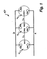
- FIG. 1 a multi-stage membrane suction pump 10 is shown.
- the membrane suction pump 10 has at least two, in particular three pump chambers H 1 , H 2 and H 3 .
- the pump chambers H 1 , H 2 and H 3 each have one, at least one inlet valve SV1, SV2 and SV3 having fluid inlet and one, at least one outlet valve DV1, DV2 or DV3 fluid outlet.
- the membrane suction pump 10 has a, the fluid inlets of the pump chambers H 1 , H 2 and H 3 connecting suction line A and a, the fluid outlets connecting pressure line B.
- each successive pumping rooms D 1 , H 2 and H 3 are each at least one connecting line C1 or C2 connected to one another in such a way that the diaphragm suction pump 1 on reaching and in particular when a differential pressure in the suction line A from a parallel operation of their pump chambers H 1 , H 2 and H 3 in a serially operating operation of these pumping rooms D 1st , H 2 and H 3 passes.
- each successive pump chambers interconnecting connecting lines C1 and C2 have a smaller in comparison to the suction line A and the pressure line B smaller line cross-section.
- the subsequent pumping stage D 1 , H 2 and H 3 opening check valve is interposed.
- two check valves RV1, RV2 and RV3, RV4 are interposed, one of which is arranged upstream and the other outflow side.
- diaphragm suction pump 10 has in its at least one, subsequent pumping stages D 1 , H 2 and H 3 interconnecting connecting line C1, C2 at least one check valve RV1, RV2 and RV3, RV4.
- a harmful space is possibly limited to the remaining to the check valve portion of the connecting line C1 or C2. Since the at least one check valve RV1, RV2 or RV3, RV4 makes a throttle in the connecting line C1 or C2 dispensable, is an undesirable performance-reducing condensate formation during conveying damp vapors counteracted.
- connecting lines C1 and C2 take effect only in the region of the final vacuum and since the connecting lines C1 and C2 have to handle only comparatively low flow rates in this pumping phase, the clear cross section of these connecting lines C1 and C2 compared to the suction line A and the pressure line B comparatively be carried out small.
- This also makes it possible to design the check valves RV1, RV2 or RV3, RV4 provided in the connecting line C1 or C2 with a very small flow cross-section and correspondingly small diameter compared to the suction valves SV1, SV2, SV3 and pressure valves DV1, DV2, DV3.
- the at least one check valve due to the low mass of its movable valve or locking body when closing the suction and pressure valves react quickly and thereby prevents the diaphragm pump 1 promotes insufficient or insufficient in a transition region of the pressure differences.
- the diaphragm pump 10 therefore allows with relatively simple technical means to generate the highest possible final vacuum in the shortest possible time.
- the diaphragm pump 10 has in the, the pump chambers H 1 , H 2 and H 3 interconnecting connecting lines C1 and C2 both inflow and outflow check valves RV1, RV2 and RV3, RV4, compared to the inlet and outlet valves SV1 , SV2, SV3 and DV1, DV2, DV3 of these pumping rooms are much smaller dimensions. Since the movable valve body of these check valves RV1, RV2, RV3 and RV4 thus also have lower moving masses and can respond accordingly faster, an approximation to the optimal switching point between parallel and serial operation is much favored.
- each of the check valves associated with the adjacent pump space H 1 , H 2 and H 3 line section associated, compared to the inlet and outlet valves has a much smaller clear line cross-section.
- the heads suck together via the line A and push out together via the line B.
- the valves DV1, DV2, SV2 and SV3 work as check valves and close the flow.
- the heads are thereby connected in series. Gas flow is now via: A-SV1-RV1-C1-RV2-RV3-C2-RV4-DV3-B.
- diaphragm suction pump can not only be designed in two or three stages - but can also have more than three pump stages.
- FIG. 2 is a four-stage diaphragm suction pump with four pump chambers H 1 , H 2 , H 3 and H 4 shown.
- the pump rooms H 1 , H 2 , H 3 , H 4 of in FIG. 2 shown diaphragm suction pump 10 each have one, at least one inlet valve SV1, SV2, SV3 and SV4 having fluid inlet and a, at least one outlet valve DV1, DV2, DV3 and DV4 having fluid outlet.
- the successive pumping spaces D 1 , H 2 , H 3 , H 4 are each via a connecting line C1, C2, C3 connected to each other such that the membrane suction pump 10 in FIG.
- a check valve RV1, RV2, RV3, RV4, RV5, RV6 are interposed in the connecting spaces H 1 , H 2 , H 3 , H 4 interconnecting connecting lines C1, C2, C3 both on the inlet side and on the outlet side.
- the membrane suction pump 10 can also have more than four pump chambers H 1 , H 2 , H 3 , H 4 , H 5 .
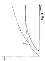
- FIG. 3 is the capacity or the pumping speed in the FIGS. 1 and 2 illustrated membrane suction pump 10 shown as a function of the achieved vacuum. While the solid line shows the pumping speed of a single-headed pump, which is limited in the achievable ultimate vacuum, it is indicated by a dot-dash line that parallel-switched pump chambers do not differ in the achievable ultimate vacuum, but rather in the delivery rate. If the pump chambers of a multi-head diaphragm suction pump are connected in series, the pumping speed is comparable with a single-headed diaphragm pump, but the pump chambers connected in series can reach a much lower ultimate vacuum (see dashed line in FIG Fig. 3 ).
- FIG. 4 is the first pumping stage H 1 one with FIG. 1 or 2 comparable multi-head diaphragm suction pump shown. While the fluid inlet located outside the cutting plane is not shown, the outlet valve DV1 interposed in the fluid outlet and the check valve RV1 provided in the connection line C1 are clearly visible. From a comparison of the valves DV1 and RV1 is clear that the here provided in the inflow region of the connecting line C1 check valve RV1 is formed smaller in comparison to the intake and exhaust valves of the pump chambers, and that this check valve RV1 to the adjacent pump chamber H 1 open towards the line section L a of the connecting line C1 is associated with a smaller compared to the inlet and outlet valves clear line cross-section.
- the connecting line C1 becomes effective only in the region of the optimum switching point, and since the connecting line C1 only has to handle comparatively low flow rates in this pumping phase, the clear cross section of this connecting line C1 can be made comparatively small in comparison with the suction line and the pressure line.
- This also makes it possible, inter alia, to carry out the check valve RV1 provided in the connection line C1 with a very small flow cross-section and correspondingly small diameter compared to the suction and pressure valves. But this also allows the check valve RV1 react quickly due to the low mass of its disk-shaped valve or locking body when closing the suction and pressure valves.
- the line section L a compared to the inlet and outlet valves has a much smaller clear line cross-section, the remaining between the check valve RV1 on the one hand and the adjacent pump chamber H 1 harmful space can be kept so low that the generation of a very low final vacuum is possible. While the line section L a leading to the adjacent pump space H 1 has a comparatively small clear line cross section, the line section L b provided between the check valves RV 1 and RV 2 may possibly also have a larger line cross section.
- the line sections L a and L b comparable clear line cross sections.
Landscapes
- Engineering & Computer Science (AREA)
- Mechanical Engineering (AREA)
- General Engineering & Computer Science (AREA)
- Reciprocating Pumps (AREA)
- Static Random-Access Memory (AREA)
- External Artificial Organs (AREA)
Claims (9)
- Pompe aspirante à membrane (10) à plusieurs étages, avec au moins deux chambres de pompe (H1, H2, H3) qui possèdent chacune une admission de fluide présentant au moins une soupape d'admission (SV1, SV2, SV3) et une évacuation de fluide présentant au moins une soupape d'évacuation (DV1, DV2, DV3), et avec une conduite d'aspiration (A) reliant les admissions de fluide des chambres de pompe (H1, H2, H3), sachant que des chambres de pompe successives (H1, H2, H3) sont respectivement reliées entre elles par l'intermédiaire d'au moins une conduite de liaison (C1, C2) de telle sorte que la pompe à membrane (10), à l'atteinte/au dépassement d'une pression différentielle dans la conduite d'aspiration (A), passe d'un fonctionnement en parallèle de ses chambres de pompe (H1, H2, H3) à un fonctionnement au moins également en série de ces chambres de pompe (H1, H2, H3), sachant qu'est respectivement intercalé, dans la région de flux entrant et dans la région de flux sortant de la conduite de liaison au moins unique (C1, C2), au moins un clapet antiretour (RV1, RV2, RV3, RV4) s'ouvrant vers l'étage de pompe suivant, et sachant que les clapets antiretour (RV1, RV2, RV3, RV4) prévus dans la région de flux entrant et dans la région de flux sortant de la ou des conduites de liaison (C1, C2) sont réalisés plus petits que les soupapes d'admission et d'évacuation (SV1, SV2, SV3 ; DV1, DV2, DV3) des chambres de pompe (H1, H2, H3),
caractérisée en ce qu'à ces clapets antiretour (RV1, RV2, RV3, RV4) est respectivement associé un tronçon de conduite de la conduite de liaison (C1, C2) qui est ouvert en direction de la chambre de pompe voisine (H1, H2, H3) et qui est doté d'une section de passage plus petite que les soupapes d'admission et d'évacuation (SV1, SV2, SV3 ; DV1, DV2, DV3), et en ce qu'au moins une soupape d'admission (SV2), une soupape d'évacuation (DV2) et deux clapets antiretour (RV2, RV3) débouchent respectivement dans les étages de pompe restants ou encore intermédiaires entre le premier et le dernier étage de pompe de la pompe aspirante à membrane. - Pompe aspirante selon la revendication 1, caractérisée en ce que les clapets antiretour (RV1, RV2, RV3, RV4) sont dimensionnés et/ou conçus de telle sorte que les soupapes d'admission et les soupapes d'évacuation (SV1, SV2, SV3 ; DV1, DV2, DV3) fonctionnent dans la phase de démarrage d'un processus de pompage et que les clapets antiretour (RV1, RV2, RV3, RV4) sont activés dans la phase suivante du processus de pompage, de préférence environ au point de commutation optimal.
- Pompe aspirante selon la revendication 1 ou 2, caractérisée en ce qu'un tronçon de conduite de la conduite de liaison (C1, C2) qui est relié à la chambre de pompe voisine (H1, H2, H3) est respectivement associé aux clapets antiretour (RV1, RV2, RV3, RV4), tronçon qui est dimensionné, par rapport aux soupapes d'admission et d'évacuation (SV1, SV2, SV3 ; DV1, DV2, DV3), de telle sorte que ces tronçons de conduite forment une chambre morte plus petite que ces soupapes.
- Pompe aspirante selon l'une des revendications 1 à 3, caractérisée en ce que la conduite d'aspiration (A) et/ou la conduite de refoulement (B) possèdent une plus grande section de passage que la conduite de liaison au moins unique (C1, C2).
- Pompe aspirante selon l'une des revendications 1 à 4, caractérisée en ce que les soupapes d'évacuation (DV1, DV2, DV3) sont conçues pour s'ouvrir vers l'atmosphère, éventuellement avec intercalation d'un silencieux.
- Pompe aspirante selon l'une des revendications 1 à 5, caractérisée en ce que les clapets antiretour (RV1, RV2, RV3, RV4) présentent chacun un disque de clapet comme corps de clapet ou d'obturation, et en ce que la plage de pression de la pression différentielle qui déclenche le passage au mode de fonctionnement en série peut être présélectionnée ou définie en définissant le diamètre du disque et/ou en adaptant le poids des disques de clapet.
- Pompe aspirante selon l'une des revendications 1 à 6, caractérisée en ce que les membranes associées à des étages de pompe consécutifs sont cadencées en décalage mutuel en ce qui concerne leurs mouvements d'aspiration et d'expulsion.
- Pompe aspirante selon l'une des revendications 1 à 7, caractérisée en ce que les membranes associées à des étages de pompe consécutifs sont cadencées en décalage mutuel de 180° en ce qui concerne leurs mouvements d'aspiration et d'expulsion.
- Pompe aspirante selon l'une des revendications 1 à 8, caractérisée en ce qu'au moins une soupape d'admission (SV1, SV3), une soupape d'évacuation (DV1, DV3) et un clapet antiretour (RV1, RV4) débouchent respectivement dans le premier et le dernier étages de pompe de la pompe aspirante à membrane.
Applications Claiming Priority (2)
| Application Number | Priority Date | Filing Date | Title |
|---|---|---|---|
| DE200710057945 DE102007057945B4 (de) | 2007-12-01 | 2007-12-01 | Mehrstufige Membran-Saugpumpe |
| PCT/EP2008/009493 WO2009068180A1 (fr) | 2007-12-01 | 2008-11-11 | Pompe aspirante à membrane à plusieurs étages |
Publications (2)
| Publication Number | Publication Date |
|---|---|
| EP2227636A1 EP2227636A1 (fr) | 2010-09-15 |
| EP2227636B1 true EP2227636B1 (fr) | 2011-04-13 |
Family
ID=39877522
Family Applications (1)
| Application Number | Title | Priority Date | Filing Date |
|---|---|---|---|
| EP20080853296 Active EP2227636B1 (fr) | 2007-12-01 | 2008-11-11 | Pompe aspirante à membrane à plusieurs étages |
Country Status (8)
| Country | Link |
|---|---|
| US (1) | US8628304B2 (fr) |
| EP (1) | EP2227636B1 (fr) |
| JP (1) | JP5312470B2 (fr) |
| CN (1) | CN101883924B (fr) |
| AT (1) | ATE505648T1 (fr) |
| DE (3) | DE102007057945B4 (fr) |
| ES (1) | ES2364231T3 (fr) |
| WO (1) | WO2009068180A1 (fr) |
Families Citing this family (10)
| Publication number | Priority date | Publication date | Assignee | Title |
|---|---|---|---|---|
| DE102009043644B4 (de) | 2009-09-29 | 2011-07-07 | KNF Neuberger GmbH, 79112 | Mehrstufige Membran-Saugpumpe |
| DE202009013127U1 (de) | 2009-09-29 | 2011-02-17 | Knf Neuberger Gmbh | Mehrstufige Membran-Saugpumpe |
| DE102010039829A1 (de) * | 2010-08-26 | 2012-03-01 | Prominent Dosiertechnik Gmbh | Membranpumpe mit trägheitsgesteuertem Leckergänzungsventil |
| KR101374048B1 (ko) | 2012-06-14 | 2014-03-13 | 한국과학기술연구원 | 유체 펌핑 장치, 이를 이용하는 연료전지 장치 및 연료 가스 재순환 방법 |
| DE102014217897A1 (de) * | 2014-09-08 | 2016-03-10 | Pressure Wave Systems Gmbh | Kompressorvorrichtung, eine damit ausgerüstete Kühlvorrichtung und ein Verfahren zum Betreiben der Kompressorvorrichtung und der Kühlvorrichtung |
| JP6273418B2 (ja) * | 2016-08-18 | 2018-02-07 | 株式会社メトラン | ポンプユニット、呼吸補助装置 |
| CN113042471A (zh) * | 2021-04-27 | 2021-06-29 | 深圳市卓润生物科技有限公司 | 清洗装置和清洗方法 |
| WO2024126324A1 (fr) * | 2022-12-13 | 2024-06-20 | Koninklijke Philips N.V. | Systèmes de pompe à fluide à configurations dynamiques et appareils comprenant de tels systèmes |
| CN116428159A (zh) * | 2023-04-20 | 2023-07-14 | 上海裕达实业有限公司 | 多级串并联组合隔膜泵 |
| DE202024101702U1 (de) | 2024-04-09 | 2024-04-16 | Vacuubrand Gmbh + Co Kg | Membran-Vakuumpumpe |
Family Cites Families (9)
| Publication number | Priority date | Publication date | Assignee | Title |
|---|---|---|---|---|
| US2246932A (en) * | 1939-09-21 | 1941-06-24 | Chicago Pneumatic Tool Co | Combination single and two stage vacuum pump |
| DE1829277U (de) * | 1959-07-21 | 1961-04-06 | Halbergerhuette G M B H | Vorrichtung zum selbsttaetigen umschalten von parallel- zum reihenbetrieb bei mehreren pumpen. |
| US5167837A (en) * | 1989-03-28 | 1992-12-01 | Fas-Technologies, Inc. | Filtering and dispensing system with independently activated pumps in series |
| US5135361A (en) * | 1991-03-06 | 1992-08-04 | William W. Gotherman | Pumping station in a water flow system |
| US5577390A (en) * | 1994-11-14 | 1996-11-26 | Carrier Corporation | Compressor for single or multi-stage operation |
| DE20202190U1 (de) * | 2002-02-14 | 2002-07-04 | Müller, Günter, 82110 Germering | Ventilgesteuerte Betriebsartregelung für mehrstufige Gasförderpumpen |
| AU2003216931A1 (en) | 2003-04-04 | 2004-10-25 | Electro Ad, Sl | Dual-head micro vacuum pump |
| KR101308784B1 (ko) * | 2005-11-21 | 2013-09-17 | 엔테그리스, 아이엔씨. | 소형 폼 팩터를 갖는 펌프용 시스템 및 방법 |
| DE102006043159B3 (de) * | 2006-09-14 | 2007-11-29 | Hyco-Vakuumtechnik Gmbh | Heißdampfvakuumpumpe |
-
2007
- 2007-12-01 DE DE200710057945 patent/DE102007057945B4/de active Active
- 2007-12-01 DE DE202007018538U patent/DE202007018538U1/de not_active Expired - Lifetime
-
2008
- 2008-11-11 ES ES08853296T patent/ES2364231T3/es active Active
- 2008-11-11 US US12/744,576 patent/US8628304B2/en active Active
- 2008-11-11 WO PCT/EP2008/009493 patent/WO2009068180A1/fr not_active Ceased
- 2008-11-11 DE DE200850003230 patent/DE502008003230D1/de active Active
- 2008-11-11 AT AT08853296T patent/ATE505648T1/de active
- 2008-11-11 JP JP2010535264A patent/JP5312470B2/ja active Active
- 2008-11-11 CN CN2008801184895A patent/CN101883924B/zh active Active
- 2008-11-11 EP EP20080853296 patent/EP2227636B1/fr active Active
Also Published As
| Publication number | Publication date |
|---|---|
| DE202007018538U1 (de) | 2008-10-23 |
| CN101883924A (zh) | 2010-11-10 |
| DE502008003230D1 (de) | 2011-05-26 |
| ES2364231T3 (es) | 2011-08-29 |
| WO2009068180A1 (fr) | 2009-06-04 |
| CN101883924B (zh) | 2013-06-05 |
| JP2011505515A (ja) | 2011-02-24 |
| US20100263750A1 (en) | 2010-10-21 |
| JP5312470B2 (ja) | 2013-10-09 |
| EP2227636A1 (fr) | 2010-09-15 |
| DE102007057945B4 (de) | 2009-11-05 |
| ATE505648T1 (de) | 2011-04-15 |
| DE102007057945A1 (de) | 2009-06-04 |
| US8628304B2 (en) | 2014-01-14 |
Similar Documents
| Publication | Publication Date | Title |
|---|---|---|
| EP2227636B1 (fr) | Pompe aspirante à membrane à plusieurs étages | |
| EP0723080B1 (fr) | Système de pompage à vide | |
| DE3225626A1 (de) | Membranpumpe | |
| DE19940498A1 (de) | Membranpumpe | |
| EP1710435B2 (fr) | Compresseur de réfrigérant | |
| EP2483560B1 (fr) | Pompe pour appareil de nettoyage haute pression | |
| EP2483559B1 (fr) | Pompe d'aspiration à membrane à plusieurs stages | |
| DE102021110042A1 (de) | Hydrauliksystem und Verfahren zum Betreiben eines Hydrauliksystems | |
| DE10021454C2 (de) | Vorrichtung zum Fördern feuchter Gase | |
| EP2597337A2 (fr) | Agencement hydraulique | |
| DE102014202265A1 (de) | Verdichter für ein Druckluftsystem insbesondere eines Kraftfahrzeugs | |
| EP3762638B1 (fr) | Soupape à plaque ainsi que son procédé de fonctionnement | |
| DE1089231B (de) | Selbsttaetiges, schnell umschaltendes Steuerventil | |
| DE102005040921B4 (de) | Trockenlaufender Schraubenverdichter mit pneumatisch gesteuertem Entlüftungsventil | |
| DE202009013127U1 (de) | Mehrstufige Membran-Saugpumpe | |
| DE102010042755B4 (de) | Mit Druckluft betriebener Unterdruckerzeuger | |
| EP2541073A2 (fr) | Cylindre pneumatique avec amortissement de fin de course à auto-ajustage | |
| DE1249040B (de) | Dreiwege-Doppelventil in Sicherheitsschaltung | |
| DE10148384B4 (de) | Sekundärluftventil | |
| DE102006043159B3 (de) | Heißdampfvakuumpumpe | |
| CH688287A5 (de) | Kombination von Verdraengerpumpe und Verdraengermotor, dessen Einlass- und Auslass-Ventilaggregat durch Druckpulsationen der Verdraengerpumpe gesteuert und betaetigt wird. | |
| DE102010032578B4 (de) | Ansteueranordnung für ein Sekundärluftventil | |
| DE102011018240A1 (de) | Radialpumpe mit einem in einem Gehäuse drehbar gelagerten Laufrad | |
| DE29618911U1 (de) | Pumpenanordnung | |
| DE19535677A1 (de) | Einrichtung zur Steuerung eines hydraulischen Motors |
Legal Events
| Date | Code | Title | Description |
|---|---|---|---|
| PUAI | Public reference made under article 153(3) epc to a published international application that has entered the european phase |
Free format text: ORIGINAL CODE: 0009012 |
|
| 17P | Request for examination filed |
Effective date: 20100701 |
|
| AK | Designated contracting states |
Kind code of ref document: A1 Designated state(s): AT BE BG CH CY CZ DE DK EE ES FI FR GB GR HR HU IE IS IT LI LT LU LV MC MT NL NO PL PT RO SE SI SK TR |
|
| AX | Request for extension of the european patent |
Extension state: AL BA MK RS |
|
| GRAP | Despatch of communication of intention to grant a patent |
Free format text: ORIGINAL CODE: EPIDOSNIGR1 |
|
| GRAS | Grant fee paid |
Free format text: ORIGINAL CODE: EPIDOSNIGR3 |
|
| DAX | Request for extension of the european patent (deleted) | ||
| GRAA | (expected) grant |
Free format text: ORIGINAL CODE: 0009210 |
|
| AK | Designated contracting states |
Kind code of ref document: B1 Designated state(s): AT BE BG CH CY CZ DE DK EE ES FI FR GB GR HR HU IE IS IT LI LT LU LV MC MT NL NO PL PT RO SE SI SK TR |
|
| REG | Reference to a national code |
Ref country code: GB Ref legal event code: FG4D Free format text: NOT ENGLISH |
|
| REG | Reference to a national code |
Ref country code: CH Ref legal event code: EP |
|
| REG | Reference to a national code |
Ref country code: IE Ref legal event code: FG4D Free format text: LANGUAGE OF EP DOCUMENT: GERMAN |
|
| REF | Corresponds to: |
Ref document number: 502008003230 Country of ref document: DE Date of ref document: 20110526 Kind code of ref document: P |
|
| REG | Reference to a national code |
Ref country code: DE Ref legal event code: R096 Ref document number: 502008003230 Country of ref document: DE Effective date: 20110526 |
|
| REG | Reference to a national code |
Ref country code: CH Ref legal event code: NV Representative=s name: HANS RUDOLF GACHNANG PATENTANWALT |
|
| REG | Reference to a national code |
Ref country code: NL Ref legal event code: VDEP Effective date: 20110413 |
|
| REG | Reference to a national code |
Ref country code: ES Ref legal event code: FG2A Ref document number: 2364231 Country of ref document: ES Kind code of ref document: T3 Effective date: 20110829 |
|
| LTIE | Lt: invalidation of european patent or patent extension |
Effective date: 20110413 |
|
| PG25 | Lapsed in a contracting state [announced via postgrant information from national office to epo] |
Ref country code: PT Free format text: LAPSE BECAUSE OF FAILURE TO SUBMIT A TRANSLATION OF THE DESCRIPTION OR TO PAY THE FEE WITHIN THE PRESCRIBED TIME-LIMIT Effective date: 20110816 Ref country code: HR Free format text: LAPSE BECAUSE OF FAILURE TO SUBMIT A TRANSLATION OF THE DESCRIPTION OR TO PAY THE FEE WITHIN THE PRESCRIBED TIME-LIMIT Effective date: 20110413 Ref country code: NO Free format text: LAPSE BECAUSE OF FAILURE TO SUBMIT A TRANSLATION OF THE DESCRIPTION OR TO PAY THE FEE WITHIN THE PRESCRIBED TIME-LIMIT Effective date: 20110713 Ref country code: SE Free format text: LAPSE BECAUSE OF FAILURE TO SUBMIT A TRANSLATION OF THE DESCRIPTION OR TO PAY THE FEE WITHIN THE PRESCRIBED TIME-LIMIT Effective date: 20110413 Ref country code: LT Free format text: LAPSE BECAUSE OF FAILURE TO SUBMIT A TRANSLATION OF THE DESCRIPTION OR TO PAY THE FEE WITHIN THE PRESCRIBED TIME-LIMIT Effective date: 20110413 |
|
| REG | Reference to a national code |
Ref country code: IE Ref legal event code: FD4D |
|
| PG25 | Lapsed in a contracting state [announced via postgrant information from national office to epo] |
Ref country code: GR Free format text: LAPSE BECAUSE OF FAILURE TO SUBMIT A TRANSLATION OF THE DESCRIPTION OR TO PAY THE FEE WITHIN THE PRESCRIBED TIME-LIMIT Effective date: 20110714 Ref country code: IS Free format text: LAPSE BECAUSE OF FAILURE TO SUBMIT A TRANSLATION OF THE DESCRIPTION OR TO PAY THE FEE WITHIN THE PRESCRIBED TIME-LIMIT Effective date: 20110813 Ref country code: SI Free format text: LAPSE BECAUSE OF FAILURE TO SUBMIT A TRANSLATION OF THE DESCRIPTION OR TO PAY THE FEE WITHIN THE PRESCRIBED TIME-LIMIT Effective date: 20110413 Ref country code: CY Free format text: LAPSE BECAUSE OF FAILURE TO SUBMIT A TRANSLATION OF THE DESCRIPTION OR TO PAY THE FEE WITHIN THE PRESCRIBED TIME-LIMIT Effective date: 20110413 Ref country code: LV Free format text: LAPSE BECAUSE OF FAILURE TO SUBMIT A TRANSLATION OF THE DESCRIPTION OR TO PAY THE FEE WITHIN THE PRESCRIBED TIME-LIMIT Effective date: 20110413 Ref country code: FI Free format text: LAPSE BECAUSE OF FAILURE TO SUBMIT A TRANSLATION OF THE DESCRIPTION OR TO PAY THE FEE WITHIN THE PRESCRIBED TIME-LIMIT Effective date: 20110413 |
|
| PG25 | Lapsed in a contracting state [announced via postgrant information from national office to epo] |
Ref country code: NL Free format text: LAPSE BECAUSE OF FAILURE TO SUBMIT A TRANSLATION OF THE DESCRIPTION OR TO PAY THE FEE WITHIN THE PRESCRIBED TIME-LIMIT Effective date: 20110413 |
|
| PG25 | Lapsed in a contracting state [announced via postgrant information from national office to epo] |
Ref country code: CZ Free format text: LAPSE BECAUSE OF FAILURE TO SUBMIT A TRANSLATION OF THE DESCRIPTION OR TO PAY THE FEE WITHIN THE PRESCRIBED TIME-LIMIT Effective date: 20110413 Ref country code: EE Free format text: LAPSE BECAUSE OF FAILURE TO SUBMIT A TRANSLATION OF THE DESCRIPTION OR TO PAY THE FEE WITHIN THE PRESCRIBED TIME-LIMIT Effective date: 20110413 Ref country code: IE Free format text: LAPSE BECAUSE OF FAILURE TO SUBMIT A TRANSLATION OF THE DESCRIPTION OR TO PAY THE FEE WITHIN THE PRESCRIBED TIME-LIMIT Effective date: 20110413 |
|
| PLBE | No opposition filed within time limit |
Free format text: ORIGINAL CODE: 0009261 |
|
| STAA | Information on the status of an ep patent application or granted ep patent |
Free format text: STATUS: NO OPPOSITION FILED WITHIN TIME LIMIT |
|
| PG25 | Lapsed in a contracting state [announced via postgrant information from national office to epo] |
Ref country code: SK Free format text: LAPSE BECAUSE OF FAILURE TO SUBMIT A TRANSLATION OF THE DESCRIPTION OR TO PAY THE FEE WITHIN THE PRESCRIBED TIME-LIMIT Effective date: 20110413 Ref country code: RO Free format text: LAPSE BECAUSE OF FAILURE TO SUBMIT A TRANSLATION OF THE DESCRIPTION OR TO PAY THE FEE WITHIN THE PRESCRIBED TIME-LIMIT Effective date: 20110413 Ref country code: DK Free format text: LAPSE BECAUSE OF FAILURE TO SUBMIT A TRANSLATION OF THE DESCRIPTION OR TO PAY THE FEE WITHIN THE PRESCRIBED TIME-LIMIT Effective date: 20110413 Ref country code: PL Free format text: LAPSE BECAUSE OF FAILURE TO SUBMIT A TRANSLATION OF THE DESCRIPTION OR TO PAY THE FEE WITHIN THE PRESCRIBED TIME-LIMIT Effective date: 20110413 |
|
| 26N | No opposition filed |
Effective date: 20120116 |
|
| REG | Reference to a national code |
Ref country code: DE Ref legal event code: R097 Ref document number: 502008003230 Country of ref document: DE Effective date: 20120116 |
|
| BERE | Be: lapsed |
Owner name: KNF NEUBERGER G.M.B.H. Effective date: 20111130 |
|
| PG25 | Lapsed in a contracting state [announced via postgrant information from national office to epo] |
Ref country code: MC Free format text: LAPSE BECAUSE OF NON-PAYMENT OF DUE FEES Effective date: 20111130 |
|
| PG25 | Lapsed in a contracting state [announced via postgrant information from national office to epo] |
Ref country code: BE Free format text: LAPSE BECAUSE OF NON-PAYMENT OF DUE FEES Effective date: 20111130 |
|
| PG25 | Lapsed in a contracting state [announced via postgrant information from national office to epo] |
Ref country code: MT Free format text: LAPSE BECAUSE OF FAILURE TO SUBMIT A TRANSLATION OF THE DESCRIPTION OR TO PAY THE FEE WITHIN THE PRESCRIBED TIME-LIMIT Effective date: 20110413 |
|
| PG25 | Lapsed in a contracting state [announced via postgrant information from national office to epo] |
Ref country code: LU Free format text: LAPSE BECAUSE OF NON-PAYMENT OF DUE FEES Effective date: 20111111 |
|
| PG25 | Lapsed in a contracting state [announced via postgrant information from national office to epo] |
Ref country code: BG Free format text: LAPSE BECAUSE OF FAILURE TO SUBMIT A TRANSLATION OF THE DESCRIPTION OR TO PAY THE FEE WITHIN THE PRESCRIBED TIME-LIMIT Effective date: 20110713 |
|
| PG25 | Lapsed in a contracting state [announced via postgrant information from national office to epo] |
Ref country code: TR Free format text: LAPSE BECAUSE OF FAILURE TO SUBMIT A TRANSLATION OF THE DESCRIPTION OR TO PAY THE FEE WITHIN THE PRESCRIBED TIME-LIMIT Effective date: 20110413 |
|
| PG25 | Lapsed in a contracting state [announced via postgrant information from national office to epo] |
Ref country code: HU Free format text: LAPSE BECAUSE OF FAILURE TO SUBMIT A TRANSLATION OF THE DESCRIPTION OR TO PAY THE FEE WITHIN THE PRESCRIBED TIME-LIMIT Effective date: 20110413 |
|
| REG | Reference to a national code |
Ref country code: CH Ref legal event code: NV Representative=s name: GACHNANG AG PATENTANWAELTE, CH |
|
| REG | Reference to a national code |
Ref country code: AT Ref legal event code: MM01 Ref document number: 505648 Country of ref document: AT Kind code of ref document: T Effective date: 20131111 |
|
| PG25 | Lapsed in a contracting state [announced via postgrant information from national office to epo] |
Ref country code: AT Free format text: LAPSE BECAUSE OF NON-PAYMENT OF DUE FEES Effective date: 20131111 |
|
| REG | Reference to a national code |
Ref country code: FR Ref legal event code: PLFP Year of fee payment: 9 |
|
| REG | Reference to a national code |
Ref country code: FR Ref legal event code: PLFP Year of fee payment: 10 |
|
| P01 | Opt-out of the competence of the unified patent court (upc) registered |
Effective date: 20230601 |
|
| REG | Reference to a national code |
Ref country code: CH Ref legal event code: PK Free format text: BERICHTIGUNGEN |
|
| REG | Reference to a national code |
Ref country code: CH Ref legal event code: U11 Free format text: ST27 STATUS EVENT CODE: U-0-0-U10-U11 (AS PROVIDED BY THE NATIONAL OFFICE) Effective date: 20251201 |
|
| PGFP | Annual fee paid to national office [announced via postgrant information from national office to epo] |
Ref country code: GB Payment date: 20251120 Year of fee payment: 18 |
|
| PGFP | Annual fee paid to national office [announced via postgrant information from national office to epo] |
Ref country code: IT Payment date: 20251128 Year of fee payment: 18 |
|
| PGFP | Annual fee paid to national office [announced via postgrant information from national office to epo] |
Ref country code: FR Payment date: 20251120 Year of fee payment: 18 |
|
| PGFP | Annual fee paid to national office [announced via postgrant information from national office to epo] |
Ref country code: CH Payment date: 20251201 Year of fee payment: 18 |
|
| PGFP | Annual fee paid to national office [announced via postgrant information from national office to epo] |
Ref country code: ES Payment date: 20251216 Year of fee payment: 18 |
|
| PGFP | Annual fee paid to national office [announced via postgrant information from national office to epo] |
Ref country code: DE Payment date: 20251223 Year of fee payment: 18 |