EP2228046B1 - Modulare fluidisierbare Insassenstütze und kompaktes fluidisierbares Modul - Google Patents
Modulare fluidisierbare Insassenstütze und kompaktes fluidisierbares Modul Download PDFInfo
- Publication number
- EP2228046B1 EP2228046B1 EP20100250471 EP10250471A EP2228046B1 EP 2228046 B1 EP2228046 B1 EP 2228046B1 EP 20100250471 EP20100250471 EP 20100250471 EP 10250471 A EP10250471 A EP 10250471A EP 2228046 B1 EP2228046 B1 EP 2228046B1
- Authority
- EP
- European Patent Office
- Prior art keywords
- fluidizable
- module
- support
- occupant
- occupant support
- Prior art date
- Legal status (The legal status is an assumption and is not a legal conclusion. Google has not performed a legal analysis and makes no representation as to the accuracy of the status listed.)
- Not-in-force
Links
- 239000000945 filler Substances 0.000 claims description 3
- 239000000463 material Substances 0.000 description 15
- 239000003570 air Substances 0.000 description 8
- 239000011324 bead Substances 0.000 description 8
- 239000006260 foam Substances 0.000 description 7
- 238000010276 construction Methods 0.000 description 4
- 238000005192 partition Methods 0.000 description 4
- 208000017520 skin disease Diseases 0.000 description 4
- 210000004712 air sac Anatomy 0.000 description 3
- 239000012530 fluid Substances 0.000 description 3
- 230000036541 health Effects 0.000 description 3
- 238000002955 isolation Methods 0.000 description 3
- 230000013011 mating Effects 0.000 description 3
- 230000005012 migration Effects 0.000 description 3
- 238000013508 migration Methods 0.000 description 3
- VYPSYNLAJGMNEJ-UHFFFAOYSA-N Silicium dioxide Chemical compound O=[Si]=O VYPSYNLAJGMNEJ-UHFFFAOYSA-N 0.000 description 2
- 239000012080 ambient air Substances 0.000 description 2
- 230000008901 benefit Effects 0.000 description 2
- 238000012423 maintenance Methods 0.000 description 2
- 230000009286 beneficial effect Effects 0.000 description 1
- 230000008878 coupling Effects 0.000 description 1
- 238000010168 coupling process Methods 0.000 description 1
- 238000005859 coupling reaction Methods 0.000 description 1
- 230000001747 exhibiting effect Effects 0.000 description 1
- 238000005243 fluidization Methods 0.000 description 1
- 210000000245 forearm Anatomy 0.000 description 1
- 230000005484 gravity Effects 0.000 description 1
- 230000007246 mechanism Effects 0.000 description 1
- 239000011236 particulate material Substances 0.000 description 1
- 230000035699 permeability Effects 0.000 description 1
- 239000011148 porous material Substances 0.000 description 1
- 230000009467 reduction Effects 0.000 description 1
- 238000000926 separation method Methods 0.000 description 1
- 235000012239 silicon dioxide Nutrition 0.000 description 1
- 239000000377 silicon dioxide Substances 0.000 description 1
Images


Classifications
-
- A—HUMAN NECESSITIES
- A61—MEDICAL OR VETERINARY SCIENCE; HYGIENE
- A61G—TRANSPORT, PERSONAL CONVEYANCES, OR ACCOMMODATION SPECIALLY ADAPTED FOR PATIENTS OR DISABLED PERSONS; OPERATING TABLES OR CHAIRS; CHAIRS FOR DENTISTRY; FUNERAL DEVICES
- A61G7/00—Beds specially adapted for nursing; Devices for lifting patients or disabled persons
- A61G7/05—Parts, details or accessories of beds
- A61G7/057—Arrangements for preventing bed-sores or for supporting patients with burns, e.g. mattresses specially adapted therefor
- A61G7/05738—Arrangements for preventing bed-sores or for supporting patients with burns, e.g. mattresses specially adapted therefor with fluid-like particles, e.g. sand, mud, seeds, gel, beads
- A61G7/05746—Arrangements for preventing bed-sores or for supporting patients with burns, e.g. mattresses specially adapted therefor with fluid-like particles, e.g. sand, mud, seeds, gel, beads fluidised by air flow
-
- A—HUMAN NECESSITIES
- A61—MEDICAL OR VETERINARY SCIENCE; HYGIENE
- A61G—TRANSPORT, PERSONAL CONVEYANCES, OR ACCOMMODATION SPECIALLY ADAPTED FOR PATIENTS OR DISABLED PERSONS; OPERATING TABLES OR CHAIRS; CHAIRS FOR DENTISTRY; FUNERAL DEVICES
- A61G7/00—Beds specially adapted for nursing; Devices for lifting patients or disabled persons
- A61G7/05—Parts, details or accessories of beds
- A61G7/057—Arrangements for preventing bed-sores or for supporting patients with burns, e.g. mattresses specially adapted therefor
- A61G7/05769—Arrangements for preventing bed-sores or for supporting patients with burns, e.g. mattresses specially adapted therefor with inflatable chambers
Definitions
- the subject matter described herein relates to fluidizable occupant supports and particularly to a modular fluidizable occupant support and a compact fluidizable module for use as a component of the modular occupant support or as a stand-alone unit.
- a typical fluidizable bed includes a vessel and a porous diffuser board or plate separating the interior volume of the vessel into a supply plenum and a fluidizable medium receptacle.
- the supply plenum is connected to a source of pressurized gas, usually ambient air that has been compressed by a compressor.
- a fluidizable particulate material usually in the form of small beads, resides in the fluidizable medium receptacle.
- a liner is secured to the containment vessel near a rim thereof.
- a filter sheet is joined to the liner at a seam.
- the seam is tight enough to resist migration of the beads through the seam and ideally is also substantially fluid-tight.
- a gas permeable vent region of the filter sheet extends across the top of the containment vessel. The vent region has pores that are small enough to resist migration of the beads through the filter sheet. When the fluidizable bed is not in a state of fluidized operation, the vent region of the filter sheet is in a slack or relaxed state.
- pressurized air enters the air distribution chamber, flows through the diffuser partition and the fluidizable material, and exhausts through the filter sheet.
- the velocity of the air flowing through the material "fluidizes" the material so that the material and air, taken together, exhibit fluid-like properties.
- the occupant of the bed is supported on a quasi-fluid having a specific gravity greater than that of the occupant.
- Such a system of support is beneficial for occupants suffering from skin disorders or at significant risk of developing skin disorders.
- Fluidizable beds typically weigh about 1000-1600 pounds (455-727 kg.), a considerable portion of which is the weight of the fluidizable material. Because of the specialized nature of fluidizable beds, they are frequently rented, rather than owned, and must therefore be frequently transported from one site to another. Even if a bed is owned, for example by a health care facility, it may need to be regularly transported from room to room. The weight is obviously a disadvantage in a frequently transported product. In addition, fluidizable beds may be used in a home care setting where the building structure may not be designed to support such heavy weight.
- fluidizable material must be periodically cleaned, usually at a site remote from the bed.
- the large volume and weight of the fluidizable material contributes to the cost, time and effort required to carry out the cleansing.
- the above drawbacks are amplified in fluidizable beds designed for heavier occupants, including bariatric occupants.
- US5623736 discloses an occupant support including a fluizabe portion and a non-fluidizable portion.
- An occupant support in accordance with the invention comprises at least one non-fluidizable module having a support structure for supporting the non-fluidizable module on a ground surface and at least one fluidizable module also having a support structure for supporting the fluidizable module on the ground surface.
- the fluidizable module and the non-fluidizable module are cooperable with each other to support an occupant.
- the support structure for the non-fluidizable module is designed to bear less than all of the weight of the fluidizable module.
- an occupant support including at least one non-fluidizable module and at least one fluidizable module cooperable with the non-fluidizable module to support an occupant.
- the fluidizable module is sized to support less than the full length of an adult human body.
- Also disclosed herein is a compact fluidizable module useable as a component of the occupant support or as a stand-alone unit.
- the subject matter disclosed herein reflects a recognition that not all patients require fluidized support across their entire body length and that providing support over less than the full length of the patient's body can yield noteworthy reductions in the weight and maintenance cost of a fluidizable occupant support as well as improvements in transportability of the support.
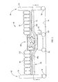
- FIG. 1 is a schematic end view of a fluidizable bed in a rest or non-fluidized state.
- FIG. 2 is a view similar to that of FIG. 1 showing the bed in a powered or fluidized state.
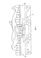
- Fig. 3 is a schematic, side elevation view of a bed having a fluidizable module and a non-fluidizable module, the support for the non-fluidizable module bearing less than all of the weight of the fluidizable module.
- Fig. 4 is a view in the direction 4--4 of FIG. 3 .
- Fig. 4A is a view in the direction 4A--4A of FIG. 4
- Fig. 5 is a view similar to FIG. 3 showing the bed with its upper body deck angularly displaced from the frame.
- Fig. 6 is a view similar to FIG. 3 showing the bed with its frame elevated to facilitate mating or unmating of the fluidizable module with the non-fluidizable module.
- Fig. 7 is a view of the fluidizable module in isolation.
- Fig. 8 is an enlarged view of an interface region between a fluidizable module and a non-fluidizable module showing an inter-cushion filler.
- Fig. 9 is a schematic, side elevation view showing a bed having a fluidizable module and a pair of non-fluidizable modules.
- Fig. 10 is a schematic, side elevation view showing an arrangement in which the non-fluidizable module is a chair of conventional design.
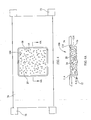
- Fig. 11 is a schematic, side elevation view of a bed having multiple stations, one of which is occupied by a fluidizable module.
- Fig. 12 is a view in the direction 12--12 of FIG 11 showing the bed frame, an opening in the frame corresponding to each of the stations and a removable cover for closing each opening.
- Fig. 12A is a view in the direction 12A--12A of FIG. 12 .
- Fig. 13 is schematic, side elevation view of an occupant support having a fluidizable module and a non-fluidizable module supported on the fluidizable module and in which the fluidizable module is sized to accommodate no more than a predefined fraction of the length of a human occupant.
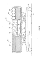
- Fig. 14 is schematic, side elevation view of a modular bed having a fluidizable module, two non-fluidizable modules, and a support structure. At least parrt of the support structure supports the combined weight of all the modules.
- FIG. 1 shows a typical non-modular fluidizable bed 10 in a rest or non-fluidized state.
- the bed includes a containment vessel 12 having a bottom 14 and a gas impermeable perimeter wall 16 extending upwardly from the vessel bottom to a wall rim 18.
- the wall 16 may be in the form of an air bladder.
- the top 22 of the vessel is open except for the presence of a filter sheet 24 described more completely below.
- a porous diffuser partition 26, often called a diffuser board or plate or simply a diffuser, cooperates with vessel wall 16 and bottom 14 to define a distribution chamber or supply plenum 28.
- a gas inlet 30 penetrates wall 16.
- the bed also includes a blower 32, which is not operating when the bed is in its rest state.
- the diffuser board and filter sheet bound a fluidizable medium receptacle 20.
- a quantity of a fluidizable material 36 such as silicon dioxide beads having a diameter on the order of about .001 inches (.0254 centimeters), occupies at least part of the volume of the receptacle 20 and may fill the vessel to a level slightly higher than the rim 18 as depicted in the illustration.
- the fluidizable material has a nominal rest depth d R .
- the bed also includes a liner 34 secured to the containment vessel.
- a snap fit seam 38 joins the filter sheet 24 to the liner.
- the seam is tight enough to resist migration of the beads past the seam.
- the seam is also fluid-tight.
- the filter sheet includes a substantially impermeable containment region 40 extending along the perimeter wall 16, and also has a permeable vent region 42 overlying the top of the vessel. When the blower is not operating, at least the vent region of the filter sheet is in a slack or relaxed state. The vent region is constructed so that, despite its permeability, the beads cannot escape through the filter sheet.
- FIG. 2 shows the bed in a powered or fluidized state.
- the blower In the fluidized state the blower is operating and pressurizes a gaseous fluid G, usually ambient air, causing the air to enter the distribution chamber by way of the gas inlet 30.
- the air then flows through the diffuser partition and the beads 36 and exhausts through the vent region 42 of the filter sheet.
- the velocity of the air flowing through the fluidizable material causes fluidization of the material so that the fluidized medium (i.e. the air and the material 36, taken together) acts as a quasi-fluid exhibiting fluid-like properties.
- the fluidized material has a fluidized depth d F which slightly exceeds its rest depth d R .
- Some beds of the type described above are constructed so that the fluidized medium supports an occupant throughout all of the occupant's length (height).
- Other beds are constructed so that the fluidized medium supports the occupant over less than all of the occupant's length, but nevertheless over a large proportion of his or her length.
- the large volume of beads gives rise to the disadvantages previously described.
- FIG. 3 shows an occupant support in the form of a hybrid bed 60 having fluidizable and non-fluidizable modules.
- the bed extends longitudinally from a head end 62 to a foot end 64 and extends laterally from a left side to a right side.
- the bed includes a non-fluidizable module 66 comprised of a head unit 70, a foot unit 72 and a frame 74 extending longitudinally between the units.
- the non-fluidizable module includes a support structure that supports the non-fluidizable module on a ground surface 76, such as a floor.
- the support structure includes the frame, portions of the head and foot units below the frame, and wheels 78.
- the frame supports a deck 84 comprising an upper body deck section 84a and a leg deck section 84b.
- One or more deck sections of the non-fluidizable module are adjustable relative to the rest of the non-fluidizable module.
- FIG. 5 illustrates the upper body deck having been angularly displaced from the frame.
- the frame 74 is elevatable relative to the floor.
- Each deck section accommodates a non-fluidizable cushion such as cushions 90 and 92.
- the deck sections may be omitted and the cushions installed directly on the frame, if desired.
- Cushions 90, 92 are illustrated as air bladders, but may be foam or any other non-fluidizable construction.
- the cushions can be built in to the deck sections or frame or may be user separable from the deck sections or frame.
- the phrase "user separable" means that the cushions can be removed from the deck section or frame without the use of special tools, skills or knowledge.
- the cushions are user separable if they can be removed and installed by the attending medical staff in a health care facility or by a home caregiver rather than requiring the intervention of maintenance or service personnel.
- the occupant support also includes a fluidizable module 100, shown in isolation in FIG. 7 , whose construction and operation is similar to that of the non-modular fluidized bed described above. That is, the module 100 has a containment vessel 12 a filter sheet 24 secured to the containment vessel and a diffuser plate 26 separating an interior volume of the vessel into a supply plenum 28 and a fluidizable medium receptacle 20. The fluidizable medium receptacle is also bounded by the filter sheet 24. A fluidizable medium 36 resides in the fluidizable medium receptacle.
- the fluidizable module includes a support structure, which may include the containment vessel 12 and wheels 102, to support the fluidizable module on a ground surface 76, such as a floor.
- the wheels also impart mobility to the fluidizable module.
- the fluidizable module when powered so that it is in its fluidized state, serves as a cushion.
- the fluidizable module is aligned with an opening 104 in the frame of the non-fluidizable module.
- the fluidizable module is sized to be able to accommodate no more than about 50% of the length of a human body, preferably no more than about 40% of the length of a human body and even more preferably no more than about 30% of the length of a human body.
- the length of the human body is the length determined from generally accepted anthropometric data.
- One source of such data is found in " The Measure of Man and Women, Human Factors in Design, Revised Edition” Alvin R. Tilley, Henry Dreyfuss Associates, John Wiley & Sons, Inc., ISBN 0-471-09955-4, 2002 .
- Another source is "PeopleSize 2000 Easy Version 2.06a", Open Ergonomics Limited.
- the length of a human body may be taken to be that of a 95th percentile male which is about 73.7 inches (approximately 187 centimeters) for a US male age 20-64 years according to the first source and about 77.8 inches (approximately 198 centimeters) for a US male age 18-64 years according to the second source.
- fluidizable and non-fluidizable modules are cooperable with each other to define a surface 110 for supporting an occupant.
- the profile of the surface is indicated by the dashed line in Fig. 3 .
- the unoccupied surface may have a nonuniform elevation to compensate for the fact that an occupant will sink into the bladders (or foam if a foam medium is used) and that the surface of the fluidizable medium may be slightly higher when fluidized than when at rest.
- the illustrations are schematic, and therefore the amount of nonuniformity depicted in the illustrations is not necessarily representative of the non-uniformity that might be present in an actual occupant support.
- an inter-cushion filler 112 FIG. 8
- the support structure for the non-fluidizable module bears none of the weight of the fluidizable module. All of the weight of the fluidizable module is supported by its own support structure. In some circumstances it may be desirable to link the fluidizable module to the non-fluidizable module in a way that the support structure for the non-fluidizable module bears a portion of the weight of the fluidizable module, but nevertheless bears less than all of the weight of the fluidizable module and preferably substantially less than all of the weight of the fluidizable module.
- the fluidizable module 100 Due to the hybrid character of the modular occupant supports described above, only part of the occupant is supported by the fluidizable module. Such partial fluidized support may be satisfactory for occupants who require the benefits of the fluidized medium along only a portion of their body. Because the fluidizable module 100 is compact in comparison to prior fluidizable constructions, which are designed for all or nearly all of an occupant's length, the overall weight of the occupant support 60 is substantially reduced. Moreover, the fluidizable module 100 is separable from the non-fluidizable module, which further eases the burdens of transporting the occupant support. For example, the frame 74 of the non-fluidizable module can be raised as seen in FIG.
- the modules may then be individually transported to their next destination.
- the nonfluidizable module 66 is easily transported because it is no longer burdened by the weight of the fluidizable medium and by the longitudinally nonuniform weight distribution that would otherwise result from the presence of the fluidizable module.
- the fluidizable module is readily portable and highly maneuverable because of its compact size and relatively low weight.
- the fluidizable module is rolled underneath the non-fluidizable module.
- the nonfluidizable module is then lowered to re-constitute the occupant support as seen in FIG. 3 .
- the frame 74 and the rim of the containment vessel 12 may include piloting features that allow the modules to mate without requiring high precision pre-positioning of the fluidizable module under the non-fluidizable module.
- piloting features may include chamfers 114 along the rim of the vessel and the mating portions of the frame.
- the fluidizable module may be height adjustable relative to the floor instead of or in addition to the frame being height adjustable relative to the floor in order to facilitate mating and unmating of the fluidizable and non-fluidizable modules.
- FIG. 9 is an occupant support similar to that of FIGS. 3 , 5 and 6 .
- the occupant support of FIGS. 3 , 5 and 6 have a single fluidizable module and a single non-fluidizable module
- the occupant support of FIG. 9 has a single fluidizable module 100 and a pair of non-fluidizable modules 66a, 66b longitudinally bracketing the fluidizable module.
- the support structure for the non-fluidizable module bears less than all of the weight of the fluidizable modules and, in the limit, bears none of the weight of the fluidizable modules. All of the weight of the fluidizable modules is supported by their own support structures.
- the quantity of fluidizable modules and non-fluidizable modules is at least three and all of the at least three modules are supportable on the ground surface 76 such that less than all of the weight of the fluidizable module is supported by the support structure of the non-fluidizable module and, in the limit, none of the weight of the fluidizable module is supported by the support structure of the non-fluidizable modules.
- FIG. 10 shows a variant in which the non-fluidizable 66 module is a chair 118 of essentially conventional design.
- FIGS 11 , 12, and 12A show a variant of the occupant support.
- the nonfluidizable module includes a frame 74 with at least two stations.
- the illustrated occupant support has three stations 120, 122, 124. At least one of the stations is capable of receiving a fluidizable cushion, e.g. a fluidizable module. In the illustration all three stations are capable of accommodating a fluidizable cushion. Each of these stations includes an opening 128.
- the occupant support includes a removable cover 130 for occupying the opening when the station is not used to accommodate a fluidizable module.
- the station When the cover is in place at a station, the station cannot accommodate a fluidizable module whose weight is not borne, at least in part, by the non-fluidizable module. However the station can accommodate a non-fluidizable cushion.
- the cover might be removed from station 122 so that a fluidizable module 100 can be used at that station, and the covers might be left in place at stations 120, 124.
- Non-fluidizable cushions comprising air bladders and/or foam pads would then be installed at stations 120 and 124.
- the occupant support would still have certain advantages over non-modular fluidizable beds, namely that transportability would be easier due to the ability to separate the fluidizable modules from the rest of the occupant support (i.e. from the non-fluidizable module) and transport the modules individually.
- an occupant support comprises at least one fluidizable module 100 and at least one non-fluidizable module 66 secured to the fluidizable module.
- the modules are cooperable with each other to support an occupant.
- the fluidizable module is sized to be able to accommodate no more than about 50% of the length of a human body, preferably no more than about 40% of the length of a human body and even more preferably no more than about 30% of the length of a human body.
- the length of the human body is the length determined from generally accepted anthropometric data as noted previously.
- the occupant support of FIG. 13 has a support structure for supporting the occupant support on a ground surface 76.
- the fluidizable module and the non-fluidizable module share a common support structure as a result of the weight of the non-fluidizable module being conveyed to the vessel 12 and thence to the ground surface 76.
- the deck portion 84 of the non-fluidizable module is pivotably connected to a bracket 134 which, in turn, is connected to or is an integral part of the containment vessel 12. The weight of the non-fluidizable module is transferred to the bracket, the vessel and finally to the wheels 102 and the floor.
- the fluidizable module may also be used as a stand-alone device rather than in conjunction with a non-fluidizable module.
- the fluidizable module shown in isolation in FIG. 7 can be employed in a stand-alone role.
- the fluidizable module is sized to be able to accommodate no more than about 50% of the length of a human body, preferably no more than about 40% of the length of a human body and even more preferably no more than about 30% of the length of a human body as determined from generally accepted anthropometric data as noted previously.
- the module 100 might be sized to accommodate only the forearm and hand of a person, in which case the wheels 102 may not be necessary.
- an occupant support includes a base frame 150 with wheels 152 for supporting the base frame on ground surface 76.
- the occupant support also includes an elevatable frame 154 and a lift mechanism, for example a scissors lift 156 for changing the elevation of the elevatable frame relative to the elevation of the base frame.
- the elevatable frame supports a fluidizable module 100 of the type already described and two non-fluidizable modules 66.
- the non-fluidizable module near one longitudinal end of the occupant support is a foam cushion 158.
- the non-fluidizable module near the other longitudinal end of the occupant support is a bladder based cushion 162.
- the support structure for the modules includes the wheels 152, base frame 150, scissors lift 156 and elevatable frame 154.
- the two non-fluidizable modules could be of the same type.
- the non-fluidizable modules could also be a construction other than foam or bladders.
- two modules can be used, one fluidizable and the other non-fluidizable.
- Three or more modules can also be used, in which case at least one module is a fluidizable module and the other modules are non-fluidizable.
- Each fluidizable module is sized to be able to accommodate no more than about 50% of the length of a human body, preferably no more than about 40% of the length of a human body and even more preferably no more than about 30% of the length of a human body as determined from generally accepted anthropometric data as noted previously.
Landscapes
- Health & Medical Sciences (AREA)
- Nursing (AREA)
- Life Sciences & Earth Sciences (AREA)
- Animal Behavior & Ethology (AREA)
- General Health & Medical Sciences (AREA)
- Public Health (AREA)
- Veterinary Medicine (AREA)
- Invalid Beds And Related Equipment (AREA)
- Mattresses And Other Support Structures For Chairs And Beds (AREA)
- Air Bags (AREA)
Claims (11)
- Patientenunterstützungsvorrichtung bestehend aus:mindestens einem nicht fluidisierbaren Modul (66) mit einer Unterlage (70, 72, 74) zur Auflagerung des nicht fluidisierbaren Moduls auf einer Bodenfläche (76);mindestens einem fluidisierbaren Modul (100) mit ebenfalls einer Unterlage (12, 102) zur Auflagerung des fluidisierbaren Moduls auf einer Bodenfläche (78);wobei das fluidisierbare Modul (100) und das nicht fluidisierbare Modul (76) zur Unterstützung eines Patienten zusammenwirken können; undwobei die Unterlage für das nicht fluidisierbare Modul weniger als das volle Gewicht des fluidisierbaren Moduls zu tragen hat.
- Patientenunterstützungsvorrichtung nach Anspruch 1, wobei die Unterlage für das nicht fluidisierbare Modul überhaupt kein Gewicht des fluidisierbaren Moduls aufzunehmen hat.
- Patientenunterstützungsvorrichtung nach entweder Anspruch 1 oder Anspruch 2, wobei mindestens das fluidisierbare Modul oder das nicht fluidisierbare Modul in der Höhe verstellbar ist.
- Patientenunterstützungsvorrichtung nach irgendeinem der vorhergehenden Ansprüche, wobei das nicht fluidisierbare Modul ein Kissen aufnimmt oder wobei das nicht fluidisierbare Modul mit einem eingearbeiteten Kissen versehen ist oder wobei das nicht fluidisierbare Modul ein vom Benutzer abnehmbares Kissen umfasst.
- Patientenunterstützungsvorrichtung nach irgendeinem der Ansprüche 1 bis 3, wobei zum nicht fluidisierbaren Modul mindestens zwei Stationen gehören, wobei mindestens eine der Stationen die Möglichkeit bietet, ein fluidisierbares Kissen aufzunehmen und wobei bevorzugt in mindestens einer der Stationen die Unterbringung eines nicht fluidisierbaren Kissens möglich ist.
- Patientenunterstützungsvorrichtung nach Anspruch 5 mit Kissen in jeder Station, wobei sich zwischen den Kissen eine Füllvorrichtung von jedem Kissen zu einem angrenzenden Kissen erstreckt.
- Patientenunterstützungsvorrichtung nach entweder Anspruch 5 oder Anspruch 6, wobei jede Station, die zur Aufnahme eines fluidisierbaren Kissens in der Lage ist, eine Öffnung für das fluidisierbare Modul aufweist und wobei die Patientenunterstützungsvorrichtung eine Abdeckung für die Öffnung des fluidisierbaren Moduls umfasst, wenn die Öffnung nicht zur Unterbringung eines fluidisierbaren Moduls genutzt wird.
- Patientenunterstützungsvorrichtung nach irgendeinem der vorhergehenden Ansprüche, wobei das fluidisierbare Modul so dimensioniert ist, dass von ihm bis zu maximal 30 Prozent der Körperlänge eines erwachsenen Menschen unterstützt werden, wobei die Körperlänge eines erwachsenen Menschen auf anthropometrischen Daten für einen Erwachsenen basiert.
- Patientenunterstützungsvorrichtung nach Anspruch 8, wobei die Körperlänge eines erwachsenen Menschen den Abmaßen von 95 Prozent der Männer entspricht.
- Patientenunterstützungsvorrichtung nach irgendeinem der vorhergehenden Ansprüche, wobei das nicht fluidisierbare Modul zumindest teilweise relativ zum Rest des nicht fluidisierbaren Moduls verstellbar ist.
- Patienhtenunterstützungsvorrichtung nach irgendeinem der vorhergehenden Ansprüche, wobei es sich bei der Anzahl der fluidisierbaren Module und nicht fluidisierbaren Module um mindestens zwei handelt, wobei alle dieser mindestens zwei Module unabhängig von den anderen Modulen auf der Bodenfläche aufgelagert werden können.
Priority Applications (2)
| Application Number | Priority Date | Filing Date | Title |
|---|---|---|---|
| EP15161490.6A EP2901995A1 (de) | 2009-03-13 | 2010-03-12 | Modulare fluidisierbare Insassenstütze und kompaktes fluidisierbares Modul |
| EP17175517.6A EP3238685B1 (de) | 2009-03-13 | 2010-03-12 | Modulare fluidisierbare insassenstütze und kompaktes fluidisierbares modul |
Applications Claiming Priority (1)
| Application Number | Priority Date | Filing Date | Title |
|---|---|---|---|
| US15999609P | 2009-03-13 | 2009-03-13 |
Related Child Applications (2)
| Application Number | Title | Priority Date | Filing Date |
|---|---|---|---|
| EP17175517.6A Division EP3238685B1 (de) | 2009-03-13 | 2010-03-12 | Modulare fluidisierbare insassenstütze und kompaktes fluidisierbares modul |
| EP15161490.6A Division EP2901995A1 (de) | 2009-03-13 | 2010-03-12 | Modulare fluidisierbare Insassenstütze und kompaktes fluidisierbares Modul |
Publications (3)
| Publication Number | Publication Date |
|---|---|
| EP2228046A2 EP2228046A2 (de) | 2010-09-15 |
| EP2228046A3 EP2228046A3 (de) | 2013-05-01 |
| EP2228046B1 true EP2228046B1 (de) | 2015-04-29 |
Family
ID=42201014
Family Applications (3)
| Application Number | Title | Priority Date | Filing Date |
|---|---|---|---|
| EP17175517.6A Not-in-force EP3238685B1 (de) | 2009-03-13 | 2010-03-12 | Modulare fluidisierbare insassenstütze und kompaktes fluidisierbares modul |
| EP20100250471 Not-in-force EP2228046B1 (de) | 2009-03-13 | 2010-03-12 | Modulare fluidisierbare Insassenstütze und kompaktes fluidisierbares Modul |
| EP15161490.6A Withdrawn EP2901995A1 (de) | 2009-03-13 | 2010-03-12 | Modulare fluidisierbare Insassenstütze und kompaktes fluidisierbares Modul |
Family Applications Before (1)
| Application Number | Title | Priority Date | Filing Date |
|---|---|---|---|
| EP17175517.6A Not-in-force EP3238685B1 (de) | 2009-03-13 | 2010-03-12 | Modulare fluidisierbare insassenstütze und kompaktes fluidisierbares modul |
Family Applications After (1)
| Application Number | Title | Priority Date | Filing Date |
|---|---|---|---|
| EP15161490.6A Withdrawn EP2901995A1 (de) | 2009-03-13 | 2010-03-12 | Modulare fluidisierbare Insassenstütze und kompaktes fluidisierbares Modul |
Country Status (2)
| Country | Link |
|---|---|
| US (1) | US10231891B2 (de) |
| EP (3) | EP3238685B1 (de) |
Families Citing this family (2)
| Publication number | Priority date | Publication date | Assignee | Title |
|---|---|---|---|---|
| US8966685B2 (en) * | 2011-07-26 | 2015-03-03 | Siemens Medical Solutions Usa, Inc. | Flexible bariatric overlay |
| US9700239B2 (en) * | 2012-07-06 | 2017-07-11 | Hill-Rom Services, Inc. | Fluidizable bed with occupancy status detection and method of occupancy status detection for a fluidizable bed |
Family Cites Families (18)
| Publication number | Priority date | Publication date | Assignee | Title |
|---|---|---|---|---|
| US452304A (en) * | 1891-05-12 | moore | ||
| US933323A (en) * | 1908-08-15 | 1909-09-07 | Wallace Invalid Bed Company | Invalid-bed. |
| US4483029A (en) * | 1981-08-10 | 1984-11-20 | Support Systems International, Inc. | Fluidized supporting apparatus |
| JPS60116351A (ja) * | 1983-11-30 | 1985-06-22 | 富士電機株式会社 | ビ−ズ流動式身体支持装置 |
| JPS61290953A (ja) | 1985-06-19 | 1986-12-20 | 富士電機株式会社 | 身体支持具 |
| US4942635A (en) * | 1988-12-20 | 1990-07-24 | Ssi Medical Services, Inc. | Dual mode patient support system |
| US5134737A (en) * | 1990-05-07 | 1992-08-04 | Freedom Corporation | Patient bed system |
| US5680661A (en) * | 1990-05-16 | 1997-10-28 | Hill-Rom, Inc. | Hospital bed with user care apparatus |
| US5687437A (en) * | 1994-02-08 | 1997-11-18 | Goldsmith; Aaron | Modular high-low adjustable bed bases retrofitted within the volumes of, and cooperatively operative with, diverse existing contour-adjustable beds so as to create high-low adjustable contour-adjustable beds |
| US5729849A (en) * | 1994-12-08 | 1998-03-24 | Garakani; Mojtaba | Sectional bed apparatus |
| US5623736A (en) * | 1994-12-09 | 1997-04-29 | Suport Systems, International | Modular inflatable/air fluidized bed |
| WO1996033641A1 (en) | 1995-04-25 | 1996-10-31 | Kinetic Concepts, Inc. | Air bed with fluidized bead surface and related methods |
| AU1385399A (en) | 1997-11-07 | 1999-05-31 | Hill-Rom, Inc. | Surgical table apparatus |
| US6101647A (en) * | 1998-03-10 | 2000-08-15 | L&P Property Management Company | Adjustable bed |
| US5950262A (en) * | 1998-04-22 | 1999-09-14 | American Echo, Inc. | Rotatable examination table |
| US6158070A (en) * | 1999-08-27 | 2000-12-12 | Hill-Rom, Inc. | Coverlet for an air bed |
| US20060022504A1 (en) * | 2004-07-26 | 2006-02-02 | Johnson Timothy A | Air fluidized granular wound care wheelchair overlay |
| AU2005277535A1 (en) * | 2004-08-16 | 2006-03-02 | John P. Biondo | Dynamic cellular person support surface |
-
2010
- 2010-01-27 US US12/694,543 patent/US10231891B2/en active Active
- 2010-03-12 EP EP17175517.6A patent/EP3238685B1/de not_active Not-in-force
- 2010-03-12 EP EP20100250471 patent/EP2228046B1/de not_active Not-in-force
- 2010-03-12 EP EP15161490.6A patent/EP2901995A1/de not_active Withdrawn
Also Published As
| Publication number | Publication date |
|---|---|
| US10231891B2 (en) | 2019-03-19 |
| EP2901995A1 (de) | 2015-08-05 |
| US20100229310A1 (en) | 2010-09-16 |
| EP3238685A1 (de) | 2017-11-01 |
| EP2228046A2 (de) | 2010-09-15 |
| EP3238685B1 (de) | 2019-02-20 |
| EP2228046A3 (de) | 2013-05-01 |
Similar Documents
| Publication | Publication Date | Title |
|---|---|---|
| EP2000057B1 (de) | Selbstnachstellende Polstervorrichtung | |
| US8844075B2 (en) | Footboard with partial mattress integration | |
| US5623736A (en) | Modular inflatable/air fluidized bed | |
| EP1901635B1 (de) | Patientenliege | |
| EP1009351B1 (de) | Vorrichtung zur hebung von kopf und oberkörper auf einer flüssigkeitsgefüllten stütze | |
| US7380302B2 (en) | Bolster system and method | |
| EP1912611B1 (de) | Patientenüberführungssystem | |
| US7155766B1 (en) | Bolster system and method | |
| JPH02213346A (ja) | 2重モード式患者支持システム | |
| US20180311089A1 (en) | Portable Cushion and Method of Use | |
| CA2316461C (en) | Coverlet for an air bed | |
| US7444693B2 (en) | Inflatable lift device | |
| EP2228046B1 (de) | Modulare fluidisierbare Insassenstütze und kompaktes fluidisierbares Modul | |
| US7975337B2 (en) | Fluidized bed | |
| EP2177194B1 (de) | Fließbett mit unterstützender Filterplatte | |
| US20140007343A1 (en) | Method of transferring a patient to a jet | |
| US20070000048A1 (en) | Pneumatic lift and method for transferring an invalid patient | |
| US20110138538A1 (en) | Weight efficient fluidized bed | |
| US12520948B2 (en) | Expandable bed | |
| EP1139966B1 (de) | Bett mit fluidisierten kügelchen und aufblasbarem diffusor | |
| US20110099721A1 (en) | Weight efficient fluidized person-support apparatus | |
| SE527705C2 (sv) | Uppblåsbart hjälpmedel för att resa patient från liggande till sittande ställning |
Legal Events
| Date | Code | Title | Description |
|---|---|---|---|
| PUAI | Public reference made under article 153(3) epc to a published international application that has entered the european phase |
Free format text: ORIGINAL CODE: 0009012 |
|
| AK | Designated contracting states |
Kind code of ref document: A2 Designated state(s): AT BE BG CH CY CZ DE DK EE ES FI FR GB GR HR HU IE IS IT LI LT LU LV MC MK MT NL NO PL PT RO SE SI SK SM TR |
|
| AX | Request for extension of the european patent |
Extension state: AL BA ME RS |
|
| RAP1 | Party data changed (applicant data changed or rights of an application transferred) |
Owner name: HILL-ROM SERVICES, INC. |
|
| RIC1 | Information provided on ipc code assigned before grant |
Ipc: A61G 7/057 20060101AFI20121206BHEP |
|
| PUAL | Search report despatched |
Free format text: ORIGINAL CODE: 0009013 |
|
| AK | Designated contracting states |
Kind code of ref document: A3 Designated state(s): AT BE BG CH CY CZ DE DK EE ES FI FR GB GR HR HU IE IS IT LI LT LU LV MC MK MT NL NO PL PT RO SE SI SK SM TR |
|
| AX | Request for extension of the european patent |
Extension state: AL BA ME RS |
|
| RIC1 | Information provided on ipc code assigned before grant |
Ipc: A61G 7/057 20060101AFI20130327BHEP |
|
| 17P | Request for examination filed |
Effective date: 20131030 |
|
| RBV | Designated contracting states (corrected) |
Designated state(s): AT BE BG CH CY CZ DE DK EE ES FI FR GB GR HR HU IE IS IT LI LT LU LV MC MK MT NL NO PL PT RO SE SI SK SM TR |
|
| GRAP | Despatch of communication of intention to grant a patent |
Free format text: ORIGINAL CODE: EPIDOSNIGR1 |
|
| INTG | Intention to grant announced |
Effective date: 20141118 |
|
| GRAS | Grant fee paid |
Free format text: ORIGINAL CODE: EPIDOSNIGR3 |
|
| GRAA | (expected) grant |
Free format text: ORIGINAL CODE: 0009210 |
|
| AK | Designated contracting states |
Kind code of ref document: B1 Designated state(s): AT BE BG CH CY CZ DE DK EE ES FI FR GB GR HR HU IE IS IT LI LT LU LV MC MK MT NL NO PL PT RO SE SI SK SM TR |
|
| REG | Reference to a national code |
Ref country code: GB Ref legal event code: FG4D |
|
| REG | Reference to a national code |
Ref country code: CH Ref legal event code: EP |
|
| REG | Reference to a national code |
Ref country code: AT Ref legal event code: REF Ref document number: 724036 Country of ref document: AT Kind code of ref document: T Effective date: 20150515 |
|
| REG | Reference to a national code |
Ref country code: IE Ref legal event code: FG4D |
|
| REG | Reference to a national code |
Ref country code: DE Ref legal event code: R096 Ref document number: 602010024273 Country of ref document: DE Effective date: 20150611 |
|
| REG | Reference to a national code |
Ref country code: NL Ref legal event code: VDEP Effective date: 20150429 |
|
| REG | Reference to a national code |
Ref country code: AT Ref legal event code: MK05 Ref document number: 724036 Country of ref document: AT Kind code of ref document: T Effective date: 20150429 |
|
| REG | Reference to a national code |
Ref country code: LT Ref legal event code: MG4D |
|
| PG25 | Lapsed in a contracting state [announced via postgrant information from national office to epo] |
Ref country code: NL Free format text: LAPSE BECAUSE OF FAILURE TO SUBMIT A TRANSLATION OF THE DESCRIPTION OR TO PAY THE FEE WITHIN THE PRESCRIBED TIME-LIMIT Effective date: 20150429 |
|
| PG25 | Lapsed in a contracting state [announced via postgrant information from national office to epo] |
Ref country code: LT Free format text: LAPSE BECAUSE OF FAILURE TO SUBMIT A TRANSLATION OF THE DESCRIPTION OR TO PAY THE FEE WITHIN THE PRESCRIBED TIME-LIMIT Effective date: 20150429 Ref country code: HR Free format text: LAPSE BECAUSE OF FAILURE TO SUBMIT A TRANSLATION OF THE DESCRIPTION OR TO PAY THE FEE WITHIN THE PRESCRIBED TIME-LIMIT Effective date: 20150429 Ref country code: FI Free format text: LAPSE BECAUSE OF FAILURE TO SUBMIT A TRANSLATION OF THE DESCRIPTION OR TO PAY THE FEE WITHIN THE PRESCRIBED TIME-LIMIT Effective date: 20150429 Ref country code: NO Free format text: LAPSE BECAUSE OF FAILURE TO SUBMIT A TRANSLATION OF THE DESCRIPTION OR TO PAY THE FEE WITHIN THE PRESCRIBED TIME-LIMIT Effective date: 20150729 Ref country code: PT Free format text: LAPSE BECAUSE OF FAILURE TO SUBMIT A TRANSLATION OF THE DESCRIPTION OR TO PAY THE FEE WITHIN THE PRESCRIBED TIME-LIMIT Effective date: 20150831 Ref country code: ES Free format text: LAPSE BECAUSE OF FAILURE TO SUBMIT A TRANSLATION OF THE DESCRIPTION OR TO PAY THE FEE WITHIN THE PRESCRIBED TIME-LIMIT Effective date: 20150429 |
|
| PG25 | Lapsed in a contracting state [announced via postgrant information from national office to epo] |
Ref country code: GR Free format text: LAPSE BECAUSE OF FAILURE TO SUBMIT A TRANSLATION OF THE DESCRIPTION OR TO PAY THE FEE WITHIN THE PRESCRIBED TIME-LIMIT Effective date: 20150730 Ref country code: AT Free format text: LAPSE BECAUSE OF FAILURE TO SUBMIT A TRANSLATION OF THE DESCRIPTION OR TO PAY THE FEE WITHIN THE PRESCRIBED TIME-LIMIT Effective date: 20150429 Ref country code: LV Free format text: LAPSE BECAUSE OF FAILURE TO SUBMIT A TRANSLATION OF THE DESCRIPTION OR TO PAY THE FEE WITHIN THE PRESCRIBED TIME-LIMIT Effective date: 20150429 Ref country code: IS Free format text: LAPSE BECAUSE OF FAILURE TO SUBMIT A TRANSLATION OF THE DESCRIPTION OR TO PAY THE FEE WITHIN THE PRESCRIBED TIME-LIMIT Effective date: 20150829 |
|
| PG25 | Lapsed in a contracting state [announced via postgrant information from national office to epo] |
Ref country code: DK Free format text: LAPSE BECAUSE OF FAILURE TO SUBMIT A TRANSLATION OF THE DESCRIPTION OR TO PAY THE FEE WITHIN THE PRESCRIBED TIME-LIMIT Effective date: 20150429 Ref country code: EE Free format text: LAPSE BECAUSE OF FAILURE TO SUBMIT A TRANSLATION OF THE DESCRIPTION OR TO PAY THE FEE WITHIN THE PRESCRIBED TIME-LIMIT Effective date: 20150429 |
|
| REG | Reference to a national code |
Ref country code: DE Ref legal event code: R097 Ref document number: 602010024273 Country of ref document: DE |
|
| REG | Reference to a national code |
Ref country code: FR Ref legal event code: PLFP Year of fee payment: 7 |
|
| PG25 | Lapsed in a contracting state [announced via postgrant information from national office to epo] |
Ref country code: PL Free format text: LAPSE BECAUSE OF FAILURE TO SUBMIT A TRANSLATION OF THE DESCRIPTION OR TO PAY THE FEE WITHIN THE PRESCRIBED TIME-LIMIT Effective date: 20150429 Ref country code: SK Free format text: LAPSE BECAUSE OF FAILURE TO SUBMIT A TRANSLATION OF THE DESCRIPTION OR TO PAY THE FEE WITHIN THE PRESCRIBED TIME-LIMIT Effective date: 20150429 Ref country code: RO Free format text: LAPSE BECAUSE OF NON-PAYMENT OF DUE FEES Effective date: 20150429 Ref country code: CZ Free format text: LAPSE BECAUSE OF FAILURE TO SUBMIT A TRANSLATION OF THE DESCRIPTION OR TO PAY THE FEE WITHIN THE PRESCRIBED TIME-LIMIT Effective date: 20150429 |
|
| PLBE | No opposition filed within time limit |
Free format text: ORIGINAL CODE: 0009261 |
|
| STAA | Information on the status of an ep patent application or granted ep patent |
Free format text: STATUS: NO OPPOSITION FILED WITHIN TIME LIMIT |
|
| 26N | No opposition filed |
Effective date: 20160201 |
|
| PG25 | Lapsed in a contracting state [announced via postgrant information from national office to epo] |
Ref country code: IT Free format text: LAPSE BECAUSE OF FAILURE TO SUBMIT A TRANSLATION OF THE DESCRIPTION OR TO PAY THE FEE WITHIN THE PRESCRIBED TIME-LIMIT Effective date: 20150429 |
|
| PG25 | Lapsed in a contracting state [announced via postgrant information from national office to epo] |
Ref country code: SI Free format text: LAPSE BECAUSE OF FAILURE TO SUBMIT A TRANSLATION OF THE DESCRIPTION OR TO PAY THE FEE WITHIN THE PRESCRIBED TIME-LIMIT Effective date: 20150429 |
|
| PG25 | Lapsed in a contracting state [announced via postgrant information from national office to epo] |
Ref country code: BE Free format text: LAPSE BECAUSE OF FAILURE TO SUBMIT A TRANSLATION OF THE DESCRIPTION OR TO PAY THE FEE WITHIN THE PRESCRIBED TIME-LIMIT Effective date: 20150429 |
|
| PG25 | Lapsed in a contracting state [announced via postgrant information from national office to epo] |
Ref country code: MC Free format text: LAPSE BECAUSE OF FAILURE TO SUBMIT A TRANSLATION OF THE DESCRIPTION OR TO PAY THE FEE WITHIN THE PRESCRIBED TIME-LIMIT Effective date: 20150429 Ref country code: LU Free format text: LAPSE BECAUSE OF FAILURE TO SUBMIT A TRANSLATION OF THE DESCRIPTION OR TO PAY THE FEE WITHIN THE PRESCRIBED TIME-LIMIT Effective date: 20160312 |
|
| REG | Reference to a national code |
Ref country code: CH Ref legal event code: PL |
|
| REG | Reference to a national code |
Ref country code: IE Ref legal event code: MM4A |
|
| PG25 | Lapsed in a contracting state [announced via postgrant information from national office to epo] |
Ref country code: LI Free format text: LAPSE BECAUSE OF NON-PAYMENT OF DUE FEES Effective date: 20160331 Ref country code: CH Free format text: LAPSE BECAUSE OF NON-PAYMENT OF DUE FEES Effective date: 20160331 Ref country code: IE Free format text: LAPSE BECAUSE OF NON-PAYMENT OF DUE FEES Effective date: 20160312 |
|
| REG | Reference to a national code |
Ref country code: FR Ref legal event code: PLFP Year of fee payment: 8 |
|
| PG25 | Lapsed in a contracting state [announced via postgrant information from national office to epo] |
Ref country code: SE Free format text: LAPSE BECAUSE OF FAILURE TO SUBMIT A TRANSLATION OF THE DESCRIPTION OR TO PAY THE FEE WITHIN THE PRESCRIBED TIME-LIMIT Effective date: 20150429 |
|
| PG25 | Lapsed in a contracting state [announced via postgrant information from national office to epo] |
Ref country code: MT Free format text: LAPSE BECAUSE OF FAILURE TO SUBMIT A TRANSLATION OF THE DESCRIPTION OR TO PAY THE FEE WITHIN THE PRESCRIBED TIME-LIMIT Effective date: 20150429 |
|
| REG | Reference to a national code |
Ref country code: FR Ref legal event code: PLFP Year of fee payment: 9 |
|
| PG25 | Lapsed in a contracting state [announced via postgrant information from national office to epo] |
Ref country code: HU Free format text: LAPSE BECAUSE OF FAILURE TO SUBMIT A TRANSLATION OF THE DESCRIPTION OR TO PAY THE FEE WITHIN THE PRESCRIBED TIME-LIMIT; INVALID AB INITIO Effective date: 20100312 Ref country code: SM Free format text: LAPSE BECAUSE OF FAILURE TO SUBMIT A TRANSLATION OF THE DESCRIPTION OR TO PAY THE FEE WITHIN THE PRESCRIBED TIME-LIMIT Effective date: 20150429 Ref country code: CY Free format text: LAPSE BECAUSE OF FAILURE TO SUBMIT A TRANSLATION OF THE DESCRIPTION OR TO PAY THE FEE WITHIN THE PRESCRIBED TIME-LIMIT Effective date: 20150429 |
|
| PG25 | Lapsed in a contracting state [announced via postgrant information from national office to epo] |
Ref country code: MK Free format text: LAPSE BECAUSE OF FAILURE TO SUBMIT A TRANSLATION OF THE DESCRIPTION OR TO PAY THE FEE WITHIN THE PRESCRIBED TIME-LIMIT Effective date: 20150429 Ref country code: MT Free format text: LAPSE BECAUSE OF FAILURE TO SUBMIT A TRANSLATION OF THE DESCRIPTION OR TO PAY THE FEE WITHIN THE PRESCRIBED TIME-LIMIT Effective date: 20160331 Ref country code: TR Free format text: LAPSE BECAUSE OF FAILURE TO SUBMIT A TRANSLATION OF THE DESCRIPTION OR TO PAY THE FEE WITHIN THE PRESCRIBED TIME-LIMIT Effective date: 20150429 |
|
| PG25 | Lapsed in a contracting state [announced via postgrant information from national office to epo] |
Ref country code: BG Free format text: LAPSE BECAUSE OF FAILURE TO SUBMIT A TRANSLATION OF THE DESCRIPTION OR TO PAY THE FEE WITHIN THE PRESCRIBED TIME-LIMIT Effective date: 20150429 |
|
| PGFP | Annual fee paid to national office [announced via postgrant information from national office to epo] |
Ref country code: DE Payment date: 20190219 Year of fee payment: 10 Ref country code: GB Payment date: 20190222 Year of fee payment: 10 |
|
| PGFP | Annual fee paid to national office [announced via postgrant information from national office to epo] |
Ref country code: FR Payment date: 20190220 Year of fee payment: 10 |
|
| REG | Reference to a national code |
Ref country code: DE Ref legal event code: R082 Ref document number: 602010024273 Country of ref document: DE Representative=s name: PRUEFER & PARTNER MBB PATENTANWAELTE RECHTSANW, DE |
|
| REG | Reference to a national code |
Ref country code: DE Ref legal event code: R119 Ref document number: 602010024273 Country of ref document: DE |
|
| PG25 | Lapsed in a contracting state [announced via postgrant information from national office to epo] |
Ref country code: FR Free format text: LAPSE BECAUSE OF NON-PAYMENT OF DUE FEES Effective date: 20200331 Ref country code: DE Free format text: LAPSE BECAUSE OF NON-PAYMENT OF DUE FEES Effective date: 20201001 |
|
| GBPC | Gb: european patent ceased through non-payment of renewal fee |
Effective date: 20200312 |
|
| PG25 | Lapsed in a contracting state [announced via postgrant information from national office to epo] |
Ref country code: GB Free format text: LAPSE BECAUSE OF NON-PAYMENT OF DUE FEES Effective date: 20200312 |