EP2228151A2 - Werkzeug zum Aufweiten eines Werkstücks - Google Patents
Werkzeug zum Aufweiten eines Werkstücks Download PDFInfo
- Publication number
- EP2228151A2 EP2228151A2 EP09177530A EP09177530A EP2228151A2 EP 2228151 A2 EP2228151 A2 EP 2228151A2 EP 09177530 A EP09177530 A EP 09177530A EP 09177530 A EP09177530 A EP 09177530A EP 2228151 A2 EP2228151 A2 EP 2228151A2
- Authority
- EP
- European Patent Office
- Prior art keywords
- tube
- pipe
- workpiece
- support portion
- deformation member
- Prior art date
- Legal status (The legal status is an assumption and is not a legal conclusion. Google has not performed a legal analysis and makes no representation as to the accuracy of the status listed.)
- Granted
Links
- 238000010438 heat treatment Methods 0.000 claims description 5
- 238000003754 machining Methods 0.000 description 15
- 238000003780 insertion Methods 0.000 description 14
- 230000037431 insertion Effects 0.000 description 14
- 238000005520 cutting process Methods 0.000 description 6
- 238000003825 pressing Methods 0.000 description 6
- 239000000463 material Substances 0.000 description 4
- 239000002131 composite material Substances 0.000 description 2
- 230000006835 compression Effects 0.000 description 2
- 238000007906 compression Methods 0.000 description 2
- 238000006073 displacement reaction Methods 0.000 description 2
- 239000002184 metal Substances 0.000 description 2
- 239000011324 bead Substances 0.000 description 1
- 230000005540 biological transmission Effects 0.000 description 1
- 239000013590 bulk material Substances 0.000 description 1
- 239000007788 liquid Substances 0.000 description 1
- 238000004519 manufacturing process Methods 0.000 description 1
- 210000003205 muscle Anatomy 0.000 description 1
- 239000011343 solid material Substances 0.000 description 1
- 125000006850 spacer group Chemical group 0.000 description 1
Images

Classifications
-
- B—PERFORMING OPERATIONS; TRANSPORTING
- B21—MECHANICAL METAL-WORKING WITHOUT ESSENTIALLY REMOVING MATERIAL; PUNCHING METAL
- B21D—WORKING OR PROCESSING OF SHEET METAL OR METAL TUBES, RODS OR PROFILES WITHOUT ESSENTIALLY REMOVING MATERIAL; PUNCHING METAL
- B21D41/00—Application of procedures in order to alter the diameter of tube ends
- B21D41/02—Enlarging
-
- B—PERFORMING OPERATIONS; TRANSPORTING
- B21—MECHANICAL METAL-WORKING WITHOUT ESSENTIALLY REMOVING MATERIAL; PUNCHING METAL
- B21D—WORKING OR PROCESSING OF SHEET METAL OR METAL TUBES, RODS OR PROFILES WITHOUT ESSENTIALLY REMOVING MATERIAL; PUNCHING METAL
- B21D17/00—Forming single grooves in sheet metal or tubular or hollow articles
- B21D17/02—Forming single grooves in sheet metal or tubular or hollow articles by pressing
-
- B—PERFORMING OPERATIONS; TRANSPORTING
- B21—MECHANICAL METAL-WORKING WITHOUT ESSENTIALLY REMOVING MATERIAL; PUNCHING METAL
- B21D—WORKING OR PROCESSING OF SHEET METAL OR METAL TUBES, RODS OR PROFILES WITHOUT ESSENTIALLY REMOVING MATERIAL; PUNCHING METAL
- B21D39/00—Application of procedures in order to connect objects or parts, e.g. coating with sheet metal otherwise than by plating; Tube expanders
- B21D39/08—Tube expanders
Definitions
- the present invention relates to an apparatus for processing a workpiece, in particular a pipe, with features according to the main claim.
- an O-ring whose outer diameter is greater than the inner diameter of the tube, not already pressed into the notch upon insertion into the tube, and a guided in the tube material (in particular a liquid and / or gas and / or Solid material, such as bulk material, can flow axially past the position of the O-ring, thereby ensuring that in the unpressed state there is always a leak in the connection between the fitting and the pipe to alert an installer in particular of a pressure drop during pressing For compression, the plastic deformation can then be radially outwardly deformed by applying a pressing tool to the tube outer wall, whereby the leakage produced by the notch and passing through the O-ring is produced by pressing the tube inner wall in the area of leakage to the OR ing canceled by plastic deformation of the pipe inner wall radially inward again.
- a guided in the tube material in particular a liquid and / or gas and / or Solid material, such as bulk material
- the DE 20 2008 005 983 U1 shows for this purpose a tool for expanding a workpiece with a round inner cross-section, in which a mandrel into one in the pipe inserted sleeve is introduced from one side of an open pipe end.
- the mandrel then presses on a jaw, which extends parallel to the tube longitudinal axis and then causes an at least partially deformation of the tube wall radially outward.
- the aim of the invention is therefore to provide a device for machining, in particular expansion, of workpieces, in particular pipes (ie metal pipes, plastic pipes and / or composite pipes) or workpieces which have at least rotational symmetry, which does not have any axial force during the machining of the pipe the open tube end exerts, through which the device according to the invention is introduced into the tube interior.
- pipes ie metal pipes, plastic pipes and / or composite pipes
- workpieces which have at least rotational symmetry, which does not have any axial force during the machining of the pipe the open tube end exerts, through which the device according to the invention is introduced into the tube interior.
- a radial direction is a direction perpendicular to the rotation axis of the support portion
- an axial direction is a direction parallel to the axis of symmetry of the support portion.
- the axis of symmetry of the support portion is parallel to an axis of rotational symmetry of the workpiece, in particular, the axis of symmetry of the support portion and the rotationally symmetric axis of the workpiece lie on each other.
- the axis of symmetry of the support section lies on the longitudinal axis of the device.
- the invention solves this problem by the subject of the main claim.
- the subclaims are directed to advantageous embodiments of the invention, wherein features of different embodiments can be combined.
- the apparatus for machining a workpiece in particular a tube, advantageously includes a deformation member for deforming a wall of the workpiece, a deflection portion which engages the deformation member and a support portion which is supported on a wall of the workpiece (advantageously an inner wall of a tube) and with is connected to the deflection section.
- machining of a workpiece is understood in particular to mean the deformation or change in the geometry of the workpiece, for example an at least regional radial expansion and / or round pressing and / or caking of a particular cylindrical and / or hollow cylindrical workpiece.
- the workpiece is in particular a tube, which may contain a metal and / or a plastic.
- the tube may therefore be a composite tube, for example.
- Further machining can also be understood as a deburring of the workpiece, ie, in the case of a pipe, in particular the removal of burrs at an open pipe end.
- the machining may further include calibrating a pipe, that is, in particular, adapting a wall thickness of the pipe jacket to a desired wall thickness, in particular at an open end of the pipe.
- the expansion of the tube means an enlargement of the tube diameter in at least one region of the tube wall (which is also referred to below as a partial expansion region), ie a deformation defined in its geometry and arrangement on the tube.
- the partial widening region is advantageously on the tube shell and in particular near an open end of the tube (which is also referred to below as the tube end).
- the deformation member is used for controlled deformation or deformation of a wall of the workpiece, ie in particular for partial expansion of a tube.
- a controlled deformation is to be understood as meaning, in particular, a deformation of the workpiece according to a fixed plan before the machining.
- the deformation member may be disposed on an outer surface or outer circumferential surface of an advantageously hollow cylindrical or advantageously at least rotationally symmetrical support section, wherein the cutout of the cylinder surface, on which the deformation member is arranged, during the deformation of a wall of the workpiece (in particular tube inner wall) is opposite.
- the cylinder axis of the support section is advantageously in the axial direction during machining.
- the support portion is inserted into the interior of the workpiece, for example, the support portion is then opposite in all directions of the pipe inner wall.
- the support portion is advantageously formed as a hollow cylinder and has arranged the deformation member on its outer circumferential surface.
- the support portion is arranged in its longitudinal direction within a support portion, wherein the longitudinal directions of support portion and support portion preferably lie parallel to each other.
- the hollow cylinder of the support portion thus has an outer diameter, which is advantageously smaller than the inner diameter of the support portion.
- the device according to the invention advantageously has a support section which is supported on a wall of the workpiece.
- the support portion is supported against a portion of a pipe inner wall (a support portion).
- the support region comprises at least one region which is diametrically opposed to the partial expansion region. But he can also rearrange this area, in particular be arranged around it.
- the support portion advantageously has a hollow cylindrical shape or at least a rotationally symmetrical shape and at least partially rearranges the support section.
- the support portion advantageously has an opening in its hollow cylinder shell through which the deformation member can pass to engage the workpiece.
- the hollow cylindrical support section advantageously has a cylinder axis which coincides with the axis of rotation of the deflection section or lies at least parallel thereto.
- the support portion exerts a counter force to the deformation force, wherein the deformation force is the force with which the deformation member deforms the workpiece.
- the support portion is advantageously at least partially inserted into a pipe opening and then abuts against the inner surface of the pipe (hereinafter also referred to as pipe inner surface).
- the device according to the invention advantageously includes a deflection section which moves the deformation member so that it engages the workpiece and can deform it.
- the deflection section is mounted rotatably relative to the support section in particular in the support section about an axis of rotation of the deflection section pointing in the longitudinal direction of the deflection section.
- the deflection portion is preferably cylindrical and / or hollow cylindrical and may be arranged with its part mounted in the support portion concentric with the support portion in this. In particular, the support portion in this part is therefore also cylindrical or hollow cylindrical.
- the outer diameter of the support portion is larger than the outer diameter of the Auslenkabitess in this case. If the support section is hollow-cylindrical, then the deflection section is preferably inserted into the interior of the hollow cylinder so that the longitudinal axes of the two sections are parallel to one another and in particular to one another.
- the deflection section can be driven by a control unit (in particular a motor or electric motor), for example by connection to a transmission, to rotate about its axis of rotation. This allows the machining of the workpiece without the need for an operator to spend his muscle power.
- the deflection section can also be manually driven by an operator to rotate about its axis of rotation.
- a manual drive device may be provided in particular at the open end of the deflection section lying outside the tube, which may for example take the form of a curve and / or a twist grip.
- the deflection section can be supported with a support region against the support section, so that the deformation force of the deformation element transmitted via the support section to the deflection section can be transmitted via the support section to a region of the inner wall of the pipe which is diametrically opposite to the partial expansion area.
- Deformation force is understood in this context to be, in particular, that force with which the deformation member deforms the workpiece.
- the support section can in particular have a greater wall thickness of its hollow cylinder than in its region introduced into the tube interior.
- the axis of rotation of the Auslenkabitess can coincide with the cylinder axis of a hollow cylindrical support portion or at least parallel to this.
- the deflection section comprises an eccentric, which in particular has a cylindrical and / or hollow cylindrical or at least rotationally symmetrical shape.
- This eccentric may have the shape of a shaft which has a surface in a specific part, in which eccentricity is to be effected, whose distance from the axis of rotation of the advantageously hollow-cylindrical deflection section is greater than the distance of a surface region of the shaft diametrically opposite this surface region.
- the longitudinal axis of the shaft, in the region in which the eccentric is arranged on it, not on the axis of rotation about which rotates the shaft; the two But axes are advantageously parallel to each other.
- the support section can move relative to the tube, in particular rotate about an axis of rotation which lies parallel to the tube longitudinal axis and slide along the tube inner surface.
- the shaft is rotatably mounted with the eccentric relative to the support portion, so that the deformation member can be moved radially outwardly through the opening of the support portion to engage the pipe inner wall.
- the support portion are rotated relative to the pipe wall, the eccentric are further rotated and the deformation member are applied at a different processing location than the aforementioned again to the pipe inner wall.
- the support section has at least one, advantageously two, calibrating sections which, in particular, run around the support section (ie, around the entire circumference of the support section) in the form of annular bulges and are advantageously integrally formed integrally with the support section.
- a Kalibrierabêt is interrupted or has a gap along its circumference when it hits in its course on the opening of the support portion through which the deformation member can be moved. The gap in the calibration section then coincides with the opening of the support section.
- the calibration sections advantageously form the only components of the support section which abut against the tube inner wall.
- the term inner wall of the pipe in particular does not refer to the edges of the pipe jacket at an open pipe end, but rather to the inner surface of the pipe (which is particularly close to the end of the pipe).
- the purpose of the calibration sections is to use the To calibrate geometry of the workpiece, in particular the tube shell or an end portion of the tube.
- the calibration sections serve to adapt its geometry to a desired geometry or to obtain its desired geometry during machining during the machining of the tube.
- the desired geometry may in particular be a nominal diameter of a pipe.
- the calibration sections are advantageously positively and / or precisely fitting to the inner wall of the pipe and exert a force on the inner circumference of the pipe (in particular in the area of its contact surface) on the inner wall, so that a selective pressure force of the deformation element does not affect the partial expansion area leads to a particular oval deformation of the tubular jacket in a region which is greater than the partial expansion area.
- the device according to the invention includes a deburrer for deburring an end portion of the workpiece.
- the deburrer can be formed or formed on the support portion and is advantageously during the machining of the workpiece outside of the workpiece, in particular outside the tube shell.
- the deburrer may be formed as a projecting portion of the support portion which engages the base of the tube shell and / or the edges of the tube shell at the open tube end through which the device according to the invention, in particular the deformation member is introduced into the tube or has been ,
- This protruding portion advantageously rearranges the said areas of the tubular jacket or lies opposite them.
- the deburrer advantageously has a diameter which is greater than the outer diameter of the tube, that is to say may preferably comprise the tube circumference at the tube end or may rest against it.
- the deburrer may be formed around the full circumference of the support portion or may be provided only in a sector on the circumference of the support portion.
- the deburrer can advantageously separate at a point which bears against an inner edge of the tubular jacket, a cutting section and / or a chip removal section or planer for removing burrs, which have arisen, for example, during the manufacture of the pipe to be machined from a longer pipe to cut off.
- This cutting section or Abspanabites can be designed, for example in the form of blades that separate the ridges.
- the Abspanabites to a larger diameter than the hollow cylindrical portion of the support portion, in particular, the Abspanabites has a diameter which is greater than the diameter of the annular Kalibrierabitese.
- the Abspanabites is thus also advantageously fully arranged around a portion of the support portion.
- the cutting section or Abspanabites include a groove into which the jacket of the open pipe end is inserted to oppose the deburring pressure on the inner edge of the pipe jacket a back pressure, or clamp the pipe jacket. The radially outer region of such a groove thus acts as a counterpart to the Abspanabites or cutting section. This is to prevent that during deburring the last portion of the tube shell is pressed in front of the open end radially outward beyond its nominal diameter.
- a bearing is arranged between the eccentric and the deformation member.
- the bearing is located between the eccentric and the support section.
- This bearing can be a tapered roller bearing or a ball bearing.
- a bearing runs in a space between the eccentric and support section, in particular along the entire inner circumference of a hollow cylindrical support section. This makes it possible for the eccentric to move relative to the deformation member, in particular to be able to rotate relative to it. Rotation of the eccentric with the eccentricity in a direction away from the position of the deformation member then causes the deformation member to move in an inward radial direction (ie, pull in) of the deformation member through the opening of the support portion.
- a rotation of the eccentric with the greater eccentricity in the direction of the deformation member then causes a displacement of the deformation member in a radial outward direction (ie a push-out) through the opening of the support portion.
- the deformation member is pressed against this inner wall and can deform the inner wall by the force exerted therewith, in particular radially expand to the outside and thus at least partially increase the pipe diameter (especially in the partial expansion area).
- the support portion thus advantageously has an opening through which the deformation member can be moved, in particular retracted and extended.
- a retraction is understood in the context of this invention that the deformation member is moved radially inwardly relative to the radius of the advantageously hollow cylindrical support portion.
- a movement in the opposite direction ie in particular radially outward relative to the support section.
- the movement is translational, i. in a linear direction along a radius of the support portion.
- the support section is not arranged rotatably relative to the support section.
- the support portion can then not rotate relative to the support portion, since at any time the deformation member is at least partially in the opening of the support portion and thus prevents rotation of the support portion relative to the support portion.
- the deformation member at least partially moves out of the opening radially outward, i. is at least partially more outer relative to the radius of the support portion than the outer periphery of the support portion when it is extended through the opening.
- the deformation member is formed linearly in the form of an elevation on the support portion, thus having a longitudinal axis parallel to the axis of rotation of the eccentric extension, which is greater than the transverse extent of the deformation member, wherein the direction of the transverse extension in particular perpendicular to the direction of the axis of rotation of the eccentric.
- the opening of the support portion, through which the deformation member can be moved advantageously has a geometry which allows a passage of the deformation member. In this respect, it is advantageous if the opening has a similar to the geometry of the deformation member linear configuration.
- the surface of the deformation member which faces during processing of the pipe inner wall or is applied to this, is advantageously rounded.
- This rounding may have a larger, equal or smaller curvature than the tube inner wall. This prevents a square widening area, which is angular in its base area, from being forced out of the tube wall, which could lead to greater mechanical stresses and possibly a breakage of the tube wall.
- the deformation member has a length in the axial direction, with which a deformation in the pipe inner wall, for example in the form of a notch can be formed so that the longitudinal extent of this deformation at least one, advantageously two O-rings opposite, between the pipe inner wall and a in the Pipe inserted fitting or connecting part are arranged. This ensures that in the unpressed state there is a leak in the connection between the fitting and the pipe so that material carried in the pipe can flow past the position of the O-rings.
- the length of the deformation member in the axial direction is dimensioned so that it is at least as large as the distance between the non-axially opposite each other and in particular pointing in different axial directions surfaces of two O-rings, which are arranged on a pipe to be inserted into the fitting.
- the deformation member can also be designed to advantageously form a marking notch in a front-side end of the workpiece, in particular of a tube into which the device according to the invention is inserted, during the course of or during the machining.
- the deformation member may also have a length in the axial direction, so that it is opposite to an end portion of the pipe wall (ie in particular an end portion of the pipe inner wall at the open end of the pipe through which the device according to the invention is introduced).
- This can during processing a permanent (advantageous plastic) deformation, in particular a radially outwardly protruding from the pipe wall notch (which is also referred to as a notch hereinafter) are formed in this end region of the pipe wall, in particular pressed.
- This notch is advantageously arranged to lie between the pipe end and an O-ring of a fitting inserted into the pipe, the O-ring being the closest to the pipe end in the axial direction attached to the fitting O-ring. But it may in particular extend in the axial direction to the open end of the tube and in the open-lying circumference of the tubular jacket (ie in particular frontally at the tube end) to be formed.
- the deformation member may also include a marking area, which protrudes further outwardly, in particular in the radial direction during machining than axially further away from the pipe end portions of the deformation member and / or a cutting device or separating device includes.
- this identification area can be a marking notch in the form of a recess (ie one example in the axial direction extending material-free area in the pipe wall) are formed or cut in the pipe wall.
- the marking notch advantageously serves to make an installer recognize, even after pressing the pipe with a fitting, that a deformation has been formed to create a leak prior to compression into the pipe. Finally, this deformation was plastically deformed back into the tube wall by the pressing, so that the tube can not visually recognize externally under certain circumstances, whether it has been processed or not.
- the device according to the invention may include a heating device for heating the deformation member.
- the deformation member can be heated to heat the material of the tube at least within the partial expansion range, to facilitate a deformation, in particular a plastic deformation.
- This can be applied to the deformation member, for example, an electrical resistance heating, which heats at least the attacking on the pipe inner surface of the deformation member to the temperature, which increases depending on the material of the pipe wall, the deformability of the pipe wall, for example, with respect to their deformability at room temperature.
- Part of the invention is also a system of an apparatus described above for processing a workpiece and a workpiece, in particular a pipe.
- the device described above may be introduced into the tube to allow processing, but the device and the tube may also be present separately from one another in the system.
- FIG. 1 shows a cross section through an inserted into a pipe device according to the invention.
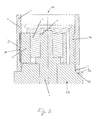
- FIG. 2 shows a longitudinal section through the device according to the invention when it is inserted into a tube.
- FIG. 1 shows a cross section through an inserted into a pipe device according to the invention, wherein the cross section intersects the deformation member 10 perpendicular to its axial extent.
- the device comprises a hollow cylindrical support section 1 with an opening in the form of a slot 13, through which a web 3 fixed to a hollow cylindrical support section 2 can be moved with a deformation member 10.
- the slot interrupts the circumference of the support portion 1 and runs in its longitudinal extent parallel to the longitudinal axis 14 of the support portion 1.
- a shaft 5 is used with an eccentric 6, whose longitudinal axis is spaced by a distance d from the longitudinal axis of the hollow cylindrical support portion 1.
- the longitudinal axis of the support section 1 advantageously comprises the axis of rotation of the shaft 5 and of the eccentric 6.
- the distance d is equal to the maximum elevation of the semi-circular deformation section 10 radially outward relative to the outer periphery of the support section 1.
- a camp 4 fully formed. So the camp has advantageous also hollow cylinder shape.
- the bearing 4 is radially outwardly adjacent to the inner surface of the hollow cylindrical support portion 2.
- the bearing 4 is also arranged rotatable about a longitudinal direction of the device according to the invention relative to the support portion 2. In FIG.
- the device according to the invention is introduced into a tube 7, wherein it can be seen that the deformation portion 10 presses into the inner wall of the tube 7.
- the processing according to the invention in particular deformation of the tubular jacket (at least on its inner side) becomes possible.
- FIG. 2 shows a longitudinal section through the device according to the invention, when it is inserted into a tube 7.
- the cut lies in a radial longitudinal plane of the web 3, on which the deformation member 10 is arranged.
- the support section 1 an insertion section 1a, which is inserted into the interior of the tube and in particular the inner surface of the tube 7 opposite, and a base portion 1b, which is located outside the tube opening and in particular integrally with the deburrer 9, its groove 9b and the outer part 9a of the groove 9b is formed comprises.
- a shaft 5 is coaxially mounted, which projects into a hollow cylindrical interior of the insertion section 1 a and has an eccentric 6.
- the longitudinal axis of the shaft 5 is spaced by a distance d from the axis of rotation of the shaft 5.
- the shaft 5 is not rotationally symmetrical to the axis of rotation 11.
- the support portion 1 is advantageously divided into two areas, wherein the base portion 1b is formed as a hollow cylinder with a thicker wall thickness than the insertion portion 1a.
- a wall portion of the base portion 1b is axially opposed to the free inner volume of the insertion portion 1a; the insertion section 1a is thus advantageously arranged on a radially outer wall region of the base section 1b.
- the insertion section 1a does not touch the inner wall of the tube 7, but has two calibrating sections 8, which for example advantageously run completely along the outer wall of the insertion section 1a as a bead or annular elevations.
- These calibration sections 8 space the outer surface of the insertion section 1a by the amount of its bead-shaped elevation over this outer surface of the inner wall of the tube 7.
- the deburrer 9 (which here comprises, for example, a rubbing surface, in particular a planer and / or a file) at least one inner surface Touched edge of the pipe end.
- the deburrer 9 comprises, for example, a rubbing surface, in particular a planer and / or a file
- the deburrer 9 By a particular rotating movement of the Entgraters 9 relative to the jacket of the tube 7 can thus be removed, in particular cutting or filing of burrs on the inner edge.
- This relative movement can take place in particular in that the support section 1 or at least the base section 1b (when this is formed rotatably about the longitudinal axis 14 relative to the insertion section 1a) take place.
- the groove 9b is adapted to receive the wall thickness of the tube 7 and thus to provide by the outer region 9a for a counter pressure during deburring.
- the calibration sections 8 take on the function of supporting sections of the support section 1 against the inner wall of the tube 7, so that a counter-pressure is created against the deformation force exerted by the deformation member 10 on the wall of the tube 7.
- the calibration sections 8 are also shown bead-like in cross-section, in order to facilitate insertion into the interior of a hollow cylindrical tube or along the inner edge of the tube end or to simplify.
- the stroke that is to say the maximum change (in particular reduction) of the distance of the longitudinal axis 12 of the eccentric 6 from the axis of rotation 11 of the shaft 5, can be limited at least in a direction of movement of the deformation member 10 pointing radially inward.
- a spacing part for example in the form of a bead-shaped or web-shaped elevation, which advantageously extends parallel to the longitudinal axis of the hollow cylindrical support section 2
- a corresponding spacer part can also be provided at the opposite point of the hollow cylindrical inner surface of the support section 1, in particular of the insertion section 1a.
- the web 13 is designed so that it can be released from the tube 7 without self-locking, when the deformation member 10 just engages in the inner surface of the tube 7.
- the outer region 9a of the groove 9b can also take over the function of the deburrer 9 for removing burrs on the outer edge of the pipe wall at the pipe opening.
- the outer region 9 a represents an outer deburrer, which may have features such as the deburrer 9. In particular, it can be constructed in the same way as the deburrer 9.
- the calibration sections 8 preferably have an outer diameter, which rests snugly on the inner wall of a tube having a pipe outer diameter of in particular 32 mm. It is also possible to construct the calibration sections 8 such that their outer diameter can rest against tubes having a different outer pipe diameter, in particular less than 32 mm or more than 32 mm.
- the base portion 1b advantageously serves as a handle for manual operation of the device according to the invention.
- the basic section 1b can have a double function as handle and carrier of the deburrer 9.
- a manual operation in particular a manual rotation of the base portion 1b for deburring and / or the shaft 5 for moving the eccentric 6 and thus the deformation member 10 is provided, in particular on the outside of the tube 7 located end of the shaft 5 may be arranged a rotating device, for example, take the form of a crank or a rotary handle.
Landscapes
- Engineering & Computer Science (AREA)
- Mechanical Engineering (AREA)
- Jigs For Machine Tools (AREA)
- Shaping Metal By Deep-Drawing, Or The Like (AREA)
- Shaping Of Tube Ends By Bending Or Straightening (AREA)
Abstract
Description
- Die vorliegende Erfindung bezieht sich auf eine Vorrichtung zur Bearbeitung eines Werkstücks, insbesondere eines Rohres, mit Merkmalen gemäß dem Hauptanspruch.
- Bei der Bearbeitung von Werkstücken, insbesondere von Rohren, ist es häufig notwendig, in ein vorgefertigtes Werkstück eine nach außen hervorstehende Verformung einzuarbeiten. Beispielsweise wird häufig in die Wand eines Rohres durch Druck auf die Rohrinnenwand eine Verformung eingebracht, die auf die Außenseite des Rohres zeigt. Insbesondere ist es häufig notwendig, zur Dichtheitsprüfung eines Rohrsystems eine Einkerbung der Rohrinnenwand nach radial außen vorzunehmen, die sich in Axialrichtung des Rohres erstreckt und vorteilhaft über die Position eines O-Rings oder mehrerer O-Ringe, der an einem in das Rohr eingeführten Fitting angebracht ist, überlagert. Dadurch wird eine Undichtigkeit der Verbindung aus Fitting und Rohr hervorgerufen. Insbesondere wird auch ein O-Ring, dessen Außendurchmesser größer als der Innendurchmesser des Rohres ist, nicht bereits beim Einschieben in das Rohr in die Kerbe hineingedrückt, und ein in dem Rohr geführtes Material (insbesondere eine Flüssigkeit und/oder ein Gas und/oder ein Feststoff, wie z.B. Schüttgut, kann in Axialrichtung über die Position des O-Rings hinwegströmen. Dadurch wird gewährleistet, dass in unverpresstem Zustand stets eine Undichtigkeit der Verbindung zwischen Fitting und Rohr vorhanden ist, um einen Installateur insbesondere über einen beim Verpressen entstehenden Druckabfall darauf hinzuweisen, dass diese Verbindung noch unverpresst ist. Zum Verpressen kann dann die plastische Verformung nach radial außen durch Anlegen eines Presswerkzeugs an die Rohraußenwand wieder nach radial innen verformt werden. Dabei wird die durch die Kerbe erzeugte über den O-Ring laufende Undichtigkeit durch Anpressen der Rohrinnenwand im Bereich der Undichtigkeit an den O-Ring durch plastische Verformung der Rohrinnenwand nach radial innen wieder aufgehoben.
- Die
DE 20 2008 005 983 U1 zeigt zu diesem Zweck ein Werkzeug zum Aufweiten eines Werkstücks mit einem runden Innenquerschnitt, bei dem ein Dorn in eine in das Rohr eingeführte Hülse von einer Seite eines offenen Rohrendes her eingeführt wird. Der Dorn drückt dann auf eine Backe, die sich parallel zur Rohrlängsachse erstreckt und dann eine zumindest bereichsweise Verformung der Rohrwand radial nach außen bewirkt. - Ziel der Erfindung ist es demzufolge, eine Vorrichtung zum Bearbeiten, insbesondere Aufweiten, von Werkstücken, insbesondere Rohren (d.h. Metallrohren, Kunststoffrohren und/oder Verbundrohren) oder Werkstücken, die wenigstens Rotationssymmetrie aufweisen, bereitzustellen, die bei der Bearbeitung des Rohres keine axiale Kraft auf das offene Rohrende ausübt, durch welches die erfindungsgemäße Vorrichtung in das Rohrinnere eingeführt wird.
- In diesem Dokument beziehen sich die Angaben "radial" und "in Axialrichtung" bzw. "axial" auf die Achse einer Rotationssymmetrie eines rotationssymmetrischen Stützabschnitts (im folgenden als Symmetrieachse des Stützabschnitts bezeichnet). Eine radiale Richtung ist demnach eine Richtung, die senkrecht auf der Rotationsachse des Stützabschnitts steht, und eine axiale Richtung ist eine Richtung, die parallel zur Symmetrieachse des Stützabschnitts verläuft. Vorteilhaft verläuft die Symmetrieachse des Stützabschnitts parallel zu einer Achse der Rotationssymmetrie des Werkstücks, insbesondere können die Symmetrieachse des Stützabschnitts und die rotationssymmetrische Achse des Werkstücks aufeinander liegen. Vorteilhaft liegt also die Symmetrieachse des Stützabschnitts auf der Längsachse der Vorrichtung.
- Die Erfindung löst diese Aufgabe durch den Gegenstand des Hauptanspruchs. Die Unteransprüche sind auf vorteilhafte Ausführungsformen der Erfindung gerichtet, wobei Merkmale unterschiedlicher Ausführungsformen kombiniert werden können.
- Die Vorrichtung zur Bearbeitung eines Werkstücks, insbesondere eines Rohres, beinhaltet vorteilhaft ein Deformationsglied zum Verformen einer Wand des Werkstücks, einen Auslenkabschnitt, der an das Deformationsglied angreift und einen Stützabschnitt, der an einer Wand des Werkstücks (vorteilhaft einer Innenwand eines Rohres) abgestützt und mit dem Auslenkabschnitt verbunden ist.
- Unter Bearbeitung eines Werkstücks wird im Folgenden insbesondere die Verformung bzw. Veränderung der Geometrie des Werkstücks, beispielsweise ein wenigstens bereichsweises radiales Aufweiten und/oder Runddrücken und/oder Aufkelchen eines insbesondere zylindrischen und/oder hohlzylindrischen Werkstücks verstanden. Das Werkstück stellt insbesondere ein Rohr dar, das ein Metall und/oder einen Kunststoff enthalten kann. Das Rohr kann also beispielsweise ein Verbundrohr sein. Unter Bearbeitung kann ferner ein Entgraten des Werkstücks, im Falle eines Rohres also insbesondere das Entfernen von Graten an einem offenen Rohrende verstanden werden. Die Bearbeitung kann ferner das Kalibrieren eines Rohrs, also insbesondere das Anpassen einer Wanddicke des Rohrmantels an eine gewünschte Wanddicke insbesondere an einem offenen Ende des Rohres umfassen. Das Aufweiten des Rohres bedeutet eine Vergrößerung des Rohrdurchmessers in wenigstens einem Bereich der Rohrwand (der im Folgenden auch als partieller Aufweitbereich bezeichnet wird), also eine in ihrer Geometrie und Anordnung an dem Rohr definierten Deformation. Der partielle Aufweitbereich liegt dabei vorteilhaft auf dem Rohrmantel und insbesondere nahe einem offenen Ende des Rohres (das im Folgenden auch als Rohrende bezeichnet wird).
- Das Deformationsglied dient zur gesteuerten Verformung bzw. Deformation einer Wand des Werkstücks, also insbesondere zur partiellen Aufweitung eines Rohres. Unter einer gesteuerten Deformation wird im Folgenden insbesondere eine Deformation des Werkstücks gemäß einem vor der Bearbeitung feststehendem Plan verstanden. Das Deformationsglied kann auf einer äußeren Oberfläche bzw. äußeren Mantelfläche eines vorteilhaft hohlzylindrischen oder vorteilhaft wenigstens rotationssymmetrischen Tragabschnitts angeordnet sein, wobei der Ausschnitt der Zylinderoberfläche, an der das Deformationsglied angeordnet ist, während der Deformation einer Wand des Werkstücks (insbesondere Rohrinnenwand) gegenüberliegt. Die Zylinderachse des Tragabschnitts liegt bei der Bearbeitung vorteilhaft in axialer Richtung. Vorzugsweise wird der Tragabschnitt in das Innere des Werkstücks eingeführt, beispielsweise liegt der Tragabschnitt dann in allen Richtungen der Rohrinnenwand gegenüber. Der Tragabschnitt ist vorteilhaft hohlzylindrisch ausgebildet und hat das Deformationsglied auf seiner äußeren Mantelfläche angeordnet. Vorteilhaft ist der Tragabschnitt in seiner Längsrichtung innerhalb eines Stützabschnitts angeordnet, wobei die Längsrichtungen von Tragabschnitt und Stützabschnitt vorzugsweise parallel zueinander liegen. Der Hohlzylinder des Tragabschnitts hat also einen Außendurchmesser, der vorteilhaft kleiner ist als der Innendurchmesser des Stützabschnitts.
- Ferner weist die erfindungsgemäße Vorrichtung vorteilhaft einen Stützabschnitt auf, der an einer Wand des Werkstücks abgestützt ist. Insbesondere wird der Stützabschnitt gegen einen Bereich einer Rohrinnenwand (einen Abstützbereich) abgestützt. Der Abstützbereich umfasst wenigstens einen Bereich, der dem partiellen Aufweitbereich diametral gegenüberliegt. Er kann aber auch diesen Bereich umlagern, insbesondere um ihn herum angeordnet sein. Der Stützabschnitt weist vorteilhaft Hohlzylinderform oder wenigstens rotationssymmetrische Form auf und umlagert wenigstens bereichsweise den Tragabschnitt. Der Stützabschnitt hat vorteilhaft eine Öffnung in seinem Hohlzylindermantel, durch die das Deformationsglied hindurchtreten kann, um an das Werkstück anzugreifen. Der hohlzylindrisch ausgebildete Stützabschnitt weist vorteilhaft eine Zylinderachse auf, die mit der Drehachse des Auslenkabschnitts übereinstimmt oder wenigstens parallel zu dieser liegt. Der Stützabschnitt übt insbesondere eine Gegenkraft zu der Deformationskraft aus, wobei die Deformationskraft diejenige Kraft ist, mit der das Deformationsglied das Werkstück verformt. Der Stützabschnitt wird vorteilhaft wenigstens bereichsweise in eine Rohröffnung eingeführt und liegt dann an der inneren Oberfläche des Rohres (im Folgenden auch als Rohrinnenfläche bezeichnet) an.
- Die erfindungsgemäße Vorrichtung beinhaltet vorteilhaft einen Auslenkabschnitt, der das Deformationsglied bewegt, so dass es an das Werkstück angreift und dieses verformen kann. Der Auslenkabschnitt ist insbesondere im Stützabschnitt um eine in Längsrichtung des Auslenkabschnitts weisende Drehachse des Auslenkabschnitts drehbar relativ zum Stützabschnitt gelagert. Der Auslenkabschnitt ist vorzugsweise zylindrisch und/oder hohlzylindrisch ausgebildet und kann mit seinem im Stützabschnitt gelagerten Teil konzentrisch zum Stützabschnitt in diesem angeordnet sein. Insbesondere ist der Stützabschnitt in diesem Teil also auch zylindrisch bzw. hohlzylindrisch ausgebildet. Der Außendurchmesser des Tragabschnitts ist in diesem Fall größer als der Außendurchmesser des Auslenkabschnitts. Ist der Stützabschnitt hohlzylindrisch ausgebildet, so ist der Auslenkabschnitt vorzugsweise in das Innere des Hohlzylinders eingefügt, so dass die Längsachsen der beiden Abschnitte parallel zueinander und insbesondere aufeinander liegen.
- Der Auslenkabschnitt kann durch eine Steuereinheit (insbesondere einen Motor bzw. Elektromotor) beispielsweise durch Verbindung mit einem Getriebe zu einer Drehung um seine Drehachse angetrieben werden. Dies ermöglicht die maschinelle Bearbeitung des Werkstücks, ohne dass ein Bediener dazu seine Muskelkraft aufwenden müsste. Der Auslenkabschnitt kann aber auch manuell durch einen Bediener zu einer Drehung um seine Drehachse angetrieben werden. Dazu kann insbesondere am offenen außerhalb des Rohres liegenden Ende des Auslenkabschnitts eine manuelle Antriebseinrichtung vorgesehen sein, die beispielsweise die Form einer Kurve und/oder eines Drehgriffs beinhaltet.
- Der Auslenkabschnitt kann mit einem Abstützbereich gegen den Stützabschnitt abgestützt werden, so dass die über den Tragabschnitt an den Auslenkabschnitt weitergegebene Deformationskraft des Deformationsglieds über den Stützabschnitt an einen, dem partiellen Aufweitbereich diametral gegenüberliegenden Bereich der Rohrinnenwand weitergegeben werden kann. Unter Deformationskraft wird in diesem Zusammenhang insbesondere diejenige Kraft verstanden, mit der das Deformationsglied das Werkstück verformt. In dem Bereich, in dem der Auslenkabschnitt in den Stützabschnitt eingelegt ist (also in einem Führungsbereich des Stützabschnitts der vorzugsweise das Hohlvolumen des Hohlzylinders umlagert), kann der Stützabschnitt insbesondere eine größere Wanddicke seines Hohlzylinders aufweisen als in seinem in das Rohrinnere eingeführten Bereich. Durch die Verspannung der erfindungsgemäßen Erfindung in dem Rohrinneren während der Deformation kann insbesondere eine erhöhte Deformationskraft erbracht werden. Die Drehachse des Auslenkabschnitts kann mit der Zylinderachse eines hohlzylindrisch ausgebildeten Stützabschnitts übereinstimmen oder wenigstens parallel zu dieser liegen.
- Vorteilhaft umfasst der Auslenkabschnitt einen Exzenter, der insbesondere zylindrische und/oder hohlzylindrische oder wenigstens rotationssymmetrische Form aufweist. Dieser Exzenter kann die Gestalt einer Welle haben, die in einen bestimmten Teil, in dem Exzentrizität bewirkt werden soll, eine Oberfläche aufweist, deren Abstand von der Drehachse des vorteilhaft hohlzylindrischen Auslenkabschnitts größer ist als der Abstand eines diesem Oberflächenbereich diametral gegenüberliegenden Oberflächenbereichs der Welle. Insbesondere liegt die Längsachse der Welle, in dem Bereich, in welchem an ihr der Exzenter angeordnet ist, nicht auf der Drehachse, um die sich die Welle dreht; die beiden Achsen liegen aber vorteilhaft parallel zueinander. Insbesondere besteht eine größere Exzentrizität der Welle in der Richtung, in der der Auslenkabschnitt an den Tragabschnitt angreift, um das Deformationsglied gegen die Rohrinnenwand zu drücken oder von dieser weg zu bewegen.
- Vorteilhaft kann sich der Stützabschnitt nach dem Einführen in das Rohr relativ zum Rohr bewegen, insbesondere um eine Drehachse, die parallel zur Rohrlängsachse liegt, drehen und an der Rohrinnenfläche entlang gleiten. Insbesondere ist die Welle mit dem Exzenter relativ zum Stützabschnitt drehbar gelagert, so dass das Deformationsglied durch die Öffnung des Stützabschnitts radial nach außen bewegt werden kann, um an der Rohrinnenwand anzugreifen. Bei einer weiteren Drehung des Exzenters ist es dann möglich, das Deformationsglied auch wieder durch die Öffnung radial nach innen zu bewegen und so von der Rohrinnenwand zu entfernen. Sodann kann z.B. der Stützabschnitt relativ zur Rohrwand verdreht werden, der Exzenter weitergedreht werden und das Deformationsglied an einer anderen Bearbeitungsstelle als der zuvor erwähnten wieder an die Rohrinnenwand angelegt werden. Dadurch wird ermöglicht, eine partielle Aufweitung eines Rohres an unterschiedlichen Stellen entlang des Rohrumfangs vorzunehmen, ohne das Rohr von der erfindungsgemäßen Vorrichtung abnehmen zu müssen und an einer anderen Position wieder aufstecken zu müssen.
- Vorteilhaft weist der Stützabschnitt wenigstens einen, vorteilhaft zwei Kalibrierabschnitte auf, die insbesondere als ringförmige Auswölbungen vollumfänglich um den Stützabschnitt (d.h. um den ganzen Umfang des Stützabschnitts) herumlaufen und vorteilhaft stoffschlüssig bzw. einteilig mit dem Stützabschnitt ausgebildet sind. Vorzugsweise ist jedoch auch ein Kalibrierabschnitt unterbrochen bzw. weist eine Lücke entlang seines Umfangs auf, wenn er in seinem Lauf auf die Öffnung des Stützabschnitts, durch die das Deformationsglied bewegt werden kann, trifft. Die Lücke im Kalibrierabschnitt deckt sich dann mit der Öffnung des Stützabschnitts. Die Kalibrierabschnitte bilden vorteilhaft die einzigen Bestandteile des Stützabschnitts, die an der Rohrinnenwand anliegen. In diesem Zusammenhang bezeichnet der Begriff der Rohrinnenwand insbesondere nicht die Kanten des Rohrmantels an einem offenen Rohrende, sondern vielmehr die innere Mantelfläche des Rohres (die insbesondere nahe am Rohrende gelegen ist). Der Zweck der Kalibrierabschnitte besteht darin, die Geometrie des Werkstücks, insbesondere des Rohrmantels bzw. eines Endabschnitts des Rohrs zu kalibrieren. Insbesondere dienen die Kalibrierabschnitte dazu, auch während der Bearbeitung des Rohres seine Geometrie an eine gewünschte Geometrie anzupassen bzw. seine gewünschte Geometrie während der Bearbeitung zu erhalten. Die gewünschte Geometrie kann insbesondere ein Nenndurchmesser eines Rohres sein. Dazu liegen die Kalibrierabschnitte vorteilhaft formschlüssig und/oder passgenau an der Rohrinnenwand an und üben auf diese vollumfänglich entlang des Innenumfangs des Rohrs (insbesondere im Bereich ihrer Kontaktfläche) eine Kraft auf die Innenwand aus, so dass eine punktuelle Druckkraft des Deformationsgliedes auf den partiellen Aufweitbereich nicht zu einer insbesondere ovalen Deformation des Rohrmantels in einem Bereich führt, der größer ist als der partielle Aufweitbereich.
- Vorteilhaft enthält die erfindungsgemäße Vorrichtung einen Entgrater zum Entgraten eines Endabschnitts des Werkstücks. Der Entgrater kann an dem Stützabschnitt angeformt bzw. ausgebildet sein und liegt vorteilhaft während der Bearbeitung des Werkstücks außerhalb des Werkstücks, insbesondere außerhalb des Rohrmantels. Beispielsweise kann der Entgrater als überstehender Abschnitt des Stützabschnitts ausgebildet sein, der an die Grundfläche des Rohrmantels und/oder an die Kanten des Rohrmantels am offen stehenden Rohrende angreift, durch welches die erfindungsgemäße Vorrichtung, insbesondere das Deformationsglied in das Rohr eingebracht wird bzw. worden ist. Dieser überstehende Abschnitt umlagert vorteilhaft die genannten Bereiche des Rohrmantels bzw. liegt ihnen gegenüber. Der Entgrater besitzt vorteilhaft einen Durchmesser, der größer ist als der Außendurchmesser des Rohres, vorzugsweise also den Rohrumfang am Rohrende umfassen bzw. an diesem anliegen kann. Der Entgrater kann rund um den vollen Umfang des Stützabschnitts ausgebildet sein oder auch nur in einem Sektor am Umfang des Stützabschnitts vorgesehen sein. Dabei kann der Entgrater vorteilhaft an einer Stelle, die an einer inneren Kante des Rohrmantels anliegt, einen Schneidabschnitt und/oder einen Abspanabschnitt bzw. Hobel zum Entfernen von Graten, die z.B. beim Herstellen des zu bearbeitenden Rohres aus einem längeren Rohr entstanden sind, abzutrennen bzw. abzuspanen. Dieser Schneidabschnitt bzw. Abspanabschnitt kann beispielsweise in Form von Klingen gestaltet sein, die die Grate abtrennen. Erfindungsgemäß möglich ist aber auch eine schleifende bzw. reibende Oberfläche eines Abspanabschnitts, mit dem die Grate insbesondere abgefeilt werden können. Vorteilhaft weist der Abspanabschnitt dazu einen größeren Durchmesser auf als der hohlzylinderische Bereich des Stützabschnitts, insbesondere weist der Abspanabschnitt einen Durchmesser auf, der größer ist als der Durchmesser der ringförmigen Kalibrierabschnitte. Der Abspanabschnitt ist somit ebenfalls vorteilhaft vollumfänglich um einen Teil des Stützabschnitts herum angeordnet. Vorteilhaft kann der Schneidabschnitt bzw. Abspanabschnitt eine Nut umfassen, in die der Mantel des offenen Rohrendes eingeführt wird, um dem beim Entgraten entstehenden Druck auf die Innenkante des Rohrmantels einen Gegendruck entgegenzusetzen, bzw. den Rohrmantel einzuspannen. Der radial außen gelegene Bereich einer solchen Nut wirkt also als Gegenstück zu dem Abspanabschnitt bzw. Schneidabschnitt. Dadurch soll verhindert werden, dass beim Entgraten der letzte Teilbereich des Rohrmantels vor dem offenen Ende radial nach außen über seinen Nenndurchmesser hinaus gedrückt wird.
- Vorteilhaft ist zwischen dem Exzenter und dem Deformationsglied ein Lager angeordnet. Insbesondere befindet sich das Lager zwischen dem Exzenter und dem Tragabschnitt. Dieses Lager kann ein Kegelrollenlager oder ein Kugellager sein. Vorteilhaft läuft ein solches Lager in einem Zwischenraum zwischen Exzenter und Tragabschnitt, insbesondere entlang des gesamten Innenumfangs eines hohlzylindrischen Tragabschnitts. Dadurch wird ermöglicht, dass der Exzenter sich relativ zum Deformationsglied bewegen, insbesondere relativ zu ihm rotieren kann. Eine Drehung des Exzenters mit der Exzentrizität in einer Richtung, die weg von der Position des Deformationsgliedes weist, bewirkt dann ein Verschieben des Deformationsglieds in eine radiale Richtung nach innen (also ein Hineinziehen) des Deformationsglieds durch die Öffnung des Stützabschnitts. Eine Drehung des Exzenters mit der größeren Exzentrizität in Richtung des Deformationsgliedes bewirkt dann ein Verschieben des Deformationsglieds in eine radiale Richtung nach außen (also ein Hinausschieben) durch die Öffnung des Stützabschnitts. Damit wird dann das Deformationsglied, wenn der Stützabschnitt so in ein Rohr eingeführt ist, dass das Deformationsglied bzw. die Öffnung des Stützabschnitts einen zu bearbeitenden Bereich der Rohrinnenwand gegenüberliegt, gegen diese Innenwand gedrückt und kann durch die damit erfolgende Kraftausübung die Innenwand verformen, insbesondere radial nach außen dehnen und somit zumindest bereichsweise den Rohrdurchmesser (insbesondere im partiellen Aufweitbereich) vergrößern.
- Der Stützabschnitt weist also vorteilhaft eine Öffnung auf, durch die das Deformationsglied bewegt, insbesondere eingefahren und ausgefahren werden kann. Unter einem Einfahren wird im Rahmen dieser Erfindung verstanden, dass das Deformationsglied radial nach innen relativ zum Radius des vorteilhaft hohlzylindrisch ausgebildeten Stützabschnitts bewegt wird. Unter einem Ausfahren wird im Rahmen dieser Erfindung eine Bewegung in die entgegengesetzte Richtung, insbesondere also radial nach außen relativ zum Stützabschnitt verstanden. Die Bewegung erfolgt translatorisch, d.h. in einer linearen Richtung entlang eines Radius des Stützabschnitts. Vorteilhaft ist der Tragabschnitt nicht rotativ relativ zum Stützabschnitt angeordnet. Der Tragabschnitt kann sich dann relativ zum Stützabschnitt nicht drehen, da zu jeder Zeit das Deformationsglied zumindest teilweise in der Öffnung des Stützabschnitts liegt und so ein Verdrehen des Tragabschnitts relativ zum Stützabschnitt verhindert. Das Deformationsglied bewegt sich jedoch erst zumindest teilweise aus der Öffnung radial nach außen heraus, d.h. befindet sich relativ zum Radius des Stützabschnitts zumindest teilweise weiter außen als der Außenumfang des Stützabschnitts, wenn es durch die Öffnung ausgefahren wird.
- Insbesondere ist das Deformationsglied linear in Form einer Erhebung auf dem Tragabschnitt ausgebildet, besitzt also eine parallel zur Rotationsachse des Exzenters gelegene Längserstreckung, die größer ist als die Quererstreckung des Deformationsglieds, wobei die Richtung der Quererstreckung insbesondere senkrecht zur Richtung der Rotationsachse des Exzenters verläuft. Die Öffnung des Stützabschnitts, durch die das Deformationsglied bewegt werden kann, besitzt vorteilhaft eine Geometrie, die ein Hindurchführen des Deformationsgliedes gestattet. Insofern ist es günstig, wenn die Öffnung eine zur Geometrie des Deformationsgliedes ähnliche lineare Ausgestaltung aufweist. Die Oberfläche des Deformationsgliedes, die bei der Bearbeitung der Rohrinnenwand zugewandt bzw. an diese angelegt wird, ist vorteilhaft abgerundet ausgebildet. Diese Abrundung kann eine größere, gleiche oder auch kleinere Krümmung als die Rohrinnenwand aufweisen. Dadurch wird verhindert, dass ein in seiner Grundfläche eckiger partieller Aufweitbereich aus der Rohrwand herausgedrückt wird, was zu größeren mechanischen Spannungen und eventuell einem Bruch der Rohrwand führen könnte.
- Vorteilhaft weist das Deformationsglied eine Länge in Axialrichtung auf, mit der eine Deformation in die Rohrinnenwand beispielsweise in Form einer Kerbe eingeformt werden kann, so dass die Längserstreckung dieser Deformation wenigstens einen, vorteilhaft zwei O-Ringen gegenüberliegt, die zwischen der Rohrinnenwand und einem in das Rohr eingeführten Fitting bzw. Verbindungsteil angeordnet sind. Dadurch wird gewährleistet, dass im unverpressten Zustand eine Undichtigkeit der Verbindung zwischen Fittung und Rohr besteht, so dass im Rohr geführtes Material über die Position der O-Ringe hinwegströmen kann. Insbesondere ist die Länge des Deformationsglieds in Axialrichtung so dimensioniert, dass sie mindestens so groß ist wie der Abstand zwischen dem in Axialrichtung einander nicht gegenüberliegenden und insbesondere in unterschiedliche Axialrichtungen weisenden Oberflächen zweier O-Ringe, die an eine in das Rohr einzuführenden Fitting angeordnet sind.
- Das Deformationsglied kann auch ausgebildet sein, um eine Kennzeichnungskerbe in ein stirnseitiges Ende des Werkstücks, insbesondere eines Rohres, in das die erfindungsgemäße Vorrichtung eingeführt wird, vorteilhaft im Zuge bzw. während der Bearbeitung zu formen. Dazu kann das Deformationsglied kann auch eine Länge in Axialrichtung aufweisen, so dass es bei der Bearbeitung einem Endbereich der Rohrwand (d. h. insbesondere einem Endbereich der Rohrinnenwand am offenen Ende des Rohres, durch das die erfindungsgemäße Vorrichtung eingeführt wird) gegenüberliegt. Damit kann bei der Bearbeitung eine dauerhafte (vorteilhaft plastische) Verformung, insbesondere eine radial nach außen aus der Rohrwand hervorstehende Kerbe (die im folgenden auch als Kennzeichnungskerbe bezeichnet wird) in diesen Endbereich der Rohrwand eingeformt, insbesondere eingedrückt werden. Diese Kerbe ist vorteilhaft so angeordnet, dass sie zwischen dem Rohrende und einem O-Ring eines in das Rohr eingeführten Fittings liegt, wobei der O-Ring der dem Rohrende in Axialrichtung am nächsten liegende an dem Fitting angebrachte O-Ring ist. Sie kann aber insbesondere sich in Axialrichtung bis ans offene Rohrende erstrecken und in den offen liegenden Umfang des Rohrmantels (also insbesondere stirnseitig am Rohrende) eingeformt sein. Vorzugsweise kann das Deformationsglied auch einen Kennzeichnungsbereich beinhalten, der insbesondere in radialer Richtung vorteilhaft bei der Bearbeitung weiter nach außen hervorsteht als axial weiter vom Rohrende entfernte Bereiche des Deformationsglieds und/oder eine Schneidvorrichtung bzw. Trennvorrichtung beinhaltet. Mit diesem Kennzeichnungsbereich kann eine Kennzeichnungskerbe in Form einer Ausnehmung (d. h. einen sich beispielsweise in Axialrichtung erstreckenden materialfreien Bereich in der Rohrwand) in die Rohrwand eingeformt bzw. geschnitten werden. Die Kennzeichnungskerbe dient vorteilhaft dazu, einen Installateur auch nach dem Verpressen des Rohres mit einem Fitting erkennen zu lassen, dass eine Deformation zu Schaffung einer Undichtigkeit vor dem Verpressen in das Rohr eingeformt worden ist. Schließlich wurde diese Deformation durch das Verpressen wieder plastisch in die Rohrwand zurückgeformt, so dass das Rohr äußerlich unter Umständen nicht mehr visuell erkennen lässt, ob es bearbeitet worden ist oder nicht.
- Vorteilhaft kann die erfindungsgemäße Vorrichtung eine Heizeinrichtung zum Heizen des Deformationsglieds beinhalten. Dadurch kann das Deformationsglied erwärmt werden, um das Material des Rohres wenigstens innerhalb des partiellen Aufweitbereiches zu erwärmen, um eine Verformung, insbesondere eine plastische Verformung, zu erleichtern. Dadurch kann an das Deformationsglied beispielsweise eine elektrische Widerstandsheizung angelegt sein, die wenigstens die an die Rohrinnenwand angreifende Oberfläche des Deformationsglieds auf die Temperatur erwärmt, die je nach dem Material der Rohrwand die Verformbarkeit der Rohrwand beispielsweise gegenüber ihrer Verformbarkeit bei Raumtemperatur erhöht.
- Bestandteil der Erfindung ist ferner ein System aus einer oben beschriebenen Vorrichtung zur Bearbeitung eines Werkstücks und einem Werkstück, insbesondere einem Rohr. Dabei kann die oben beschriebene Vorrichtung in das Rohr eingeführt sein, um eine Bearbeitung zu ermöglichen, die Vorrichtung und das Rohr können jedoch auch getrennt voneinander in dem System vorhanden sein.
-
Figur 1 zeigt einen Querschnitt durch eine in ein Rohr eingeführte erfindungsgemäße Vorrichtung. -
Figur 2 zeigt einen Längsschnitt durch die erfindungsgemäße Vorrichtung, wenn sie in ein Rohr eingeführt ist. -
Figur 1 zeigt einen Querschnitt durch eine in ein Rohr eingeführte erfindungsgemäße Vorrichtung, wobei der Querschnitt das Deformationsglied 10 senkrecht zu seiner axialen Erstreckung schneidet. Die Vorrichtung umfasst dabei einen hohlzylindrischen Stützabschnitt 1 mit einer Öffnung in Form eines Schlitzes 13, durch den ein an einem hohlzylindrischen Tragabschnitt 2 befestigter Steg 3 mit einem Deformationsglied 10 bewegt werden kann. Der Schlitz unterbricht den Umfang des Stützabschnitts 1 und läuft in seiner Längserstreckung parallel zur Längsachse 14 des Stützabschnitts 1. Als Auslenkmittel wird eine Welle 5 mit einem Exzenter 6 verwendet, dessen Längsachse um einen Abstand d von der Längsachse des hohlzylindrischen Stützabschnitts 1 beabstandet ist. Die Längsachse des Stützabschnitts 1 umfasst vorteilhaft die Drehachse der Welle 5 und des Exzenters 6. Insbesondere ist der Abstand d gleich der maximalen Erhebung des halbrund ausgebildeten Deformationsabschnitts 10 nach radial außen gegenüber dem Außenumfang des Stützabschnitts 1. Zwischen dem Exzenter 6 und dem Tragabschnitt 2 ist ein Lager 4 vollumfänglich ausgebildet. Also besitzt das Lager vorteilhaft ebenfalls Hohlzylinderform. Im Zylinderinnenraum des Lagers 4 ist dabei die Welle 5 mit dem Exzenter 6 drehbar relativ zum Lager 4 angeordnet. Das Lager 4 grenzt radial nach außen hin an die Innenfläche des hohlzylindrischen Tragabschnitts 2. Vorteilhaft ist das Lager 4 ebenfalls drehbar um eine Längsrichtung der erfindungsgemäßen Vorrichtung gegenüber dem Tragabschnitt 2 angeordnet. InFigur 1 ist die erfindungsgemäße Vorrichtung in ein Rohr 7 eingeführt, wobei erkennbar ist, dass der Defomationsabschnitt 10 in die Innenwand des Rohrs 7 eindrückt. Dadurch wird die erfindungsgemäße Bearbeitung, insbesondere Verformung des Rohrmantels (wenigstens auf seiner Innenseite) möglich. - Nach einer Drehung des Exzenters 6 um 180° aus der in
Figur 1 dargestellten Position liegt der Abstand d zwischen der Längsachse 12 des Exzenters und der Rotationsachse 14 der Welle 5 in einer um 180° an einer Axialebene 14 des Stützabschnitts 1, die senkrecht auf einer radialen Axialebene 15 durch den Steg 3 und das Deformationsglied 10 steht, gespiegelten Position. Insbesondere wird die Längsachse 15 des Exzenters 6 an der Axialebene 14 des Stützabschnitts 1 gespiegelt. Dadurch wird die Längsachse des Tragabschnitts 2 um den Abstand 2d radial verlagert, wobei eine Verlagerung der Längsachse 12 des Exzenters 6 durch die Drehachse 11 der Welle 5 erfolgt. Dadurch werden der Steg 3 und das Deformationsglied 10 um den Weg 2d radial nach innen durch den Schlitz 13 von der Innenwand der Rohres 7 wegbewegt. - Bei einer weiteren Bewegung des Exzenters 6 um 180° erfolgt eine Bewegung von Tragabschnitt 2, Steg 3 und Deformationsglied 10 in die entgegengesetzte Richtung, das heißt wieder auf die Innenwand des Rohres 7 durch die Öffnung 13 zu. Der maximale Weg, um den Steg 3 und Deformationsglied 10 hier linear bewegt werden, beträgt wiederum 2d.
-
Figur 2 zeigt einen Längsschnitt durch die erfindungsgemäße Vorrichtung, wenn sie in ein Rohr 7 eingeführt ist. Der Schnitt liegt dabei in einer radialen Längsebene des Stegs 3, an dem das Deformationsglied 10 angeordnet ist. Hierbei zeigt sich unter anderem, dass der Stützabschnitt 1 einen Einführabschnitt 1a, der in das Innere des Rohres eingeführt wird und insbesondere der Innenfläche des Rohres 7 gegenüberliegt, und einen Grundabschnitt 1b, der sich außerhalb der Rohröffnung befindet und insbesondere einstückig mit dem Entgrater 9, seiner Nut 9b sowie dem Außenteil 9a der Nut 9b ausgebildet ist, umfasst. In dem Grundabschnitt 1b ist koaxial eine Welle 5 gelagert, die in einen hohlzylindrischen Innenraum des Einführabschnitts 1a hineinragt und einen Exzenter 6 aufweist. Insbesondere ist im Bereich des Exzenters 6 die Längsachse der Welle 5 um eine Strecke d beabstandet von der Drehachse der Welle 5. Insbesondere ist im Bereich des Exzenters 6 die Welle 5 nicht rotationssymmetrisch zur Drehachse 11. - Der Stützabschnitt 1 ist in vorteilhaft zwei Bereiche aufgeteilt, wobei der Grundabschnitt 1b hohlzylindrisch ausgebildet ist mit einer dickeren Wandstärke als der Einführabschnitt 1a. Insbesondere liegt ein Wandbereich des Grundabschnitts 1b axial dem freien Innenvolumen des Einführabschnitts 1a gegenüber; der Einführabschnitt 1a ist also vorteilhaft einem radial außen liegenden Wandbereich des Grundabschnitts 1b angeordnet.
- Der Einführabschnitt 1a berührt vorteilhaft nicht die Innenwand des Rohres 7, sondern weist zwei Kalibrierabschnitte 8 auf, die beispielsweise als Wulst bzw. ringförmige Erhebungen an der Außenwand des Einführabschnittes 1a vorteilhaft vollumfänglich entlanglaufen. Diese Kalibrierabschnitte 8 beabstanden die Außenfläche des Einführabschnitts 1a um den Betrag ihrer wulstförmigen Erhebung über dieser Außenfläche von der Innenwand des Rohres 7.
- Ebenfalls in
Figur 2 ist gezeigt, dass der Entgrater 9 (der hier beispielsweise eine reibende Obefläche, insbesondere einen Hobel und/oder eine Feile umfasst) zumindest eine innere Kante des Rohrendes berührt. Durch eine insbesondere rotierende Bewegung des Entgraters 9 relativ zum Mantel des Rohres 7 kann damit ein Entfernen, insbesondere Abspanen bzw. Abfeilen von Graten an der Innenkante erfolgen. Diese Relativbewegung kann insbesondere dadurch erfolgen, dass der Stützabschnitt 1 oder wenigstens der Grundabschnitt 1b (wenn dieser rotativ um die Längsachse 14 relativ zum Einführabschnitt 1a ausgebildet ist) erfolgen. Die Nut 9b ist geeignet, um die Wanddicke des Rohres 7 aufzunehmen und so durch den Außenbereich 9a für einen Gegendruck beim Entgraten zu sorgen. - Insbesondere übernehmen die Kalibrierabschnitte 8 die Funktion von Abstützabschnitten des Stützabschnittes 1 gegen die Innenwand des Rohres 7, so dass ein Gegendruck gegen die vom Deformationsglied 10 auf die Wand des Rohres 7 ausgeübte Deformationskraft entsteht. Die Kalibrierabschnitte 8 sind ferner wulstartig im Querschnitt abgebildet, um ein Einführen in das Innere eines hohlzylindrischen Rohres bzw. ein Entlangführen an der Innenkante des Rohrendes zu unterstützen bzw. zu vereinfachen.
- Der Hub, das heißt die maximale Veränderung (insbesondere Verringerung) des Abstands der Längsachse 12 des Exzenters 6 von der Drehachse 11 der Welle 5 kann zumindest in einer radial nach innen weisenden Bewegungsrichtung des Deformationsglieds 10 begrenzt werden. Dazu kann beispielsweise an der Außenoberfläche des Tragabschnitts 2 an einer Stelle, die diametral der Position des Stegs 3 gegenüberliegt, ein Beabstandungsteil (zum Beispiel in Form einer wulstförmigen oder stegförmigen Erhebung, die sich vorteilhaft parallel zur Längsachse des hohlzylindrischen Tragabschnitts 2 erstreckt) vorgesehen sein. Ein entsprechendes Beabstandungsteil kann aber auch an der gegenüberliegenden Stelle der hohlzylindrischen Innenfläche des Stützabschnitts 1, insbesondere des Einführabschnitts 1a vorgesehen sein. Dadurch kann der Hub des Deformationsglieds 10 auf die erforderliche Deformation des Rohres abgestimmt werden.
- Der Steg 13 ist so ausgelegt, dass er sich ohne Selbsthemmung aus dem Rohr 7 lösen kann, wenn das Deformationsglied 10 gerade in die innere Oberfläche des Rohres 7 eingreift.
- Der Außenbereich 9a der Nut 9b kann ebenfalls die Funktion des Entgraters 9 zum Entfernen von Graten an der Außenkante der Rohrwand an der Rohröffnung übernehmen. In diesem Fall stellt der Außenbereich 9a einen Außenentgrater dar, der Merkmale wie der Entgrater 9 aufweisen kann. Insbesondere kann er in gleicher Weise aufgebaut sein wie der Entgrater 9.
- Die Kalibrierabschnitte 8 weisen vorzugsweise einen Außendurchmesser auf, der passgenau an der Innenwand eines Rohres mit einem Rohraußendurchmesser von insbesondere 32 mm anliegt. Es ist auch möglich, die Kalibrierabschnitte 8 so zu konstruieren, dass ihr Außendurchmesser an Rohren mit einem anderen Rohraußendurchmesser, insbesondere von weniger als 32 mm oder mehr als 32 mm anliegen kann.
- Der Grundabschnitt 1b dient vorteilhaft als Griff für ein manuelles Bedienen der erfindungsgemäßen Vorrichtung. Insofern kann dem Grundabschnitt 1b eine Doppelfunktion als Griff und Träger des Entgraters 9 zukommen. Wenn eine manuelle Bedienung, insbesondere eine manuelle Drehung des Grundabschnitts 1b zum Entgraten und/oder der Welle 5 zum Bewegen des Exzenters 6 und damit des Deformationsglieds 10 vorgesehen ist, kann insbesondere am außerhalb des Rohres 7 gelegenen Ende der Welle 5 eine Drehvorrichtung angeordnet sein, die beispielsweise die Form einer Kurbel oder eines Drehgriffs annehmen kann.
-
- 1 Stützabschnitt
- 1aEinführabschnitt des Stützabschnitts 1
- 1b Grundabschnitt des Stützabschnitts 1
- 2 Tragabschnitt
- 3 Steg
- 4 Lager
- 5 Welle
- 6 Exzenter
- 7 Rohr
- 8 Kalibrierabschnitt
- 9 Entgrater
- 10 Deformationsglied
- 11 Längsachse des Stützabschnitts 1, Drehachse der Welle 5
- 12 Längsachse des Exzenters 6
- 13 Schlitz
- 14 Axialebene des Stützabschnitts 1
- 15 Axialebene durch den Steg 3 und das Deformationsglied 10
Claims (12)
- Vorrichtung zur Bearbeitung eines Werkstücks (7), insbesondere eines Rohres, mit folgenden Merkmalen:• einem Deformationsglied (10) zum Verformen des Werkstücks (7);• einem Auslenkabschnitt (5), der an das Deformationsglied (10) angreift;• einem Stützabschnitt (1), der an eine Oberfläche des Werkstücks (7) abgestützt und mit dem Auslenkabschnitt (5)verbunden ist.
- Vorrichtung nach Anspruch 1 mit einem Entgrater (9) zum Entgraten eines Endabschnitts des Werkstücks (7).
- Vorrichtung nach einem der vorhergehenden Ansprüche, wobei der Auslenkabschnitt (5) einen Exzenter (6) beinhaltet.
- Vorrichtung nach einem der vorhergehenden Ansprüche mit einem Kalibrierabschnitt (8) zum Kalibrieren der Geometrie eines Endabschnitts des Werkstücks (7).
- Vorrichtung nach einem der Ansprüche 3 oder 4, wobei der Exzenter (6) um eine Drehachse (11) läuft, die parallel zu einer Längsachse (11) des Werkstücks (7) liegt.
- Vorrichtung nach einem der vorhergehenden Ansprüche, die ferner einen Tragabschnitt (2) für das Deformationsglied (7) umfasst, der zumindest teilweise hohlzylindrisch ausgebildet ist.
- Vorrichtung nach einem der vorhergehenden Ansprüche, wobei der Exzenter (6) zylindrisch ausgebildet ist.
- Vorrichtung nach einem der vorhergehenden Ansprüche, wobei zwischen dem Exzenter (6) und dem Deformationsglied (10) ein Lager (4) angeordnet ist.
- Vorrichtung nach einem der vorhergehenden Ansprüche, wobei der Stützabschnitt (1) eine Öffnung (13) aufweist, durch die das Deformationsglied (10) bewegt werden kann.
- Vorrichtung nach einem der vorhergehenden Ansprüche mit einer Heizeinrichtung zum Heizen des Deformationsglieds (10).
- Vorrichtung nach einem der vorhergehenden Ansprüche, wobei das Deformationsglied (10) ausgebildet ist, um eine Kennzeichnungskerbe in das Werkstück (7) zu formen.
- System aus einer Vorrichtung nach einem der vorhergehenden Ansprüche und einem Werkstück (7), insbesondere einem Rohr.
Applications Claiming Priority (1)
| Application Number | Priority Date | Filing Date | Title |
|---|---|---|---|
| DE202009003387 | 2009-03-09 |
Publications (3)
| Publication Number | Publication Date |
|---|---|
| EP2228151A2 true EP2228151A2 (de) | 2010-09-15 |
| EP2228151A3 EP2228151A3 (de) | 2014-01-01 |
| EP2228151B1 EP2228151B1 (de) | 2015-05-13 |
Family
ID=42315694
Family Applications (1)
| Application Number | Title | Priority Date | Filing Date |
|---|---|---|---|
| EP20090177530 Not-in-force EP2228151B1 (de) | 2009-03-09 | 2009-11-30 | Werkzeug zum Aufweiten eines Werkstücks |
Country Status (1)
| Country | Link |
|---|---|
| EP (1) | EP2228151B1 (de) |
Cited By (4)
| Publication number | Priority date | Publication date | Assignee | Title |
|---|---|---|---|---|
| CN107737846A (zh) * | 2017-11-14 | 2018-02-27 | 范科晨 | 带双驱动结构的铜管胀管器 |
| CN107876643A (zh) * | 2017-11-14 | 2018-04-06 | 范科晨 | 双向铜管胀管器 |
| CN107900240A (zh) * | 2017-11-14 | 2018-04-13 | 范科晨 | 带棘爪结构的行星式胀管装置 |
| CN116117012A (zh) * | 2023-04-13 | 2023-05-16 | 德州黄河建业工程有限责任公司维修养护分公司 | 一种用于水利工程管道扩口的冲压设备以及方法 |
Citations (1)
| Publication number | Priority date | Publication date | Assignee | Title |
|---|---|---|---|---|
| DE202008005983U1 (de) | 2008-04-30 | 2008-07-31 | Ipa Produktions- Und Vertriebsges.M.B.H. | Werkzeug zum Aufweiten eines Werkstücks |
Family Cites Families (3)
| Publication number | Priority date | Publication date | Assignee | Title |
|---|---|---|---|---|
| FR1352265A (fr) * | 1963-01-03 | 1964-02-14 | Machine à onduler les viroles de fûts métalliques | |
| JP3846643B2 (ja) * | 1996-01-29 | 2006-11-15 | 株式会社ショーワ | ガスシリンダ装置のシリンダ溝加工装置及び加工方法 |
| DE10325979B4 (de) * | 2003-06-07 | 2005-05-12 | Daimlerchrysler Ag | Spreizwerkzeug |
-
2009
- 2009-11-30 EP EP20090177530 patent/EP2228151B1/de not_active Not-in-force
Patent Citations (1)
| Publication number | Priority date | Publication date | Assignee | Title |
|---|---|---|---|---|
| DE202008005983U1 (de) | 2008-04-30 | 2008-07-31 | Ipa Produktions- Und Vertriebsges.M.B.H. | Werkzeug zum Aufweiten eines Werkstücks |
Cited By (4)
| Publication number | Priority date | Publication date | Assignee | Title |
|---|---|---|---|---|
| CN107737846A (zh) * | 2017-11-14 | 2018-02-27 | 范科晨 | 带双驱动结构的铜管胀管器 |
| CN107876643A (zh) * | 2017-11-14 | 2018-04-06 | 范科晨 | 双向铜管胀管器 |
| CN107900240A (zh) * | 2017-11-14 | 2018-04-13 | 范科晨 | 带棘爪结构的行星式胀管装置 |
| CN116117012A (zh) * | 2023-04-13 | 2023-05-16 | 德州黄河建业工程有限责任公司维修养护分公司 | 一种用于水利工程管道扩口的冲压设备以及方法 |
Also Published As
| Publication number | Publication date |
|---|---|
| EP2228151B1 (de) | 2015-05-13 |
| EP2228151A3 (de) | 2014-01-01 |
Similar Documents
| Publication | Publication Date | Title |
|---|---|---|
| EP2918375B1 (de) | Pressbacke, verfahren zum herstellen einer unlösbaren rohrverbindung, fitting und system aus einer pressbacke und einem fitting | |
| DE10392402T5 (de) | Umlaufende, mit Rollen versehene Rillenbildungseinrichtung für ein Rohr | |
| EP2228151B1 (de) | Werkzeug zum Aufweiten eines Werkstücks | |
| WO2013030102A1 (de) | Schneidring-vormontagegerät für rohrverschraubungen | |
| DE4410146C2 (de) | Vorrichtung zur Herstellung von Pressfittings | |
| DE102011008068A1 (de) | Vorrichtung und Verfahren zur Herstellung von Tubenrohren für Verpackungstuben | |
| WO2011113954A1 (de) | Verfahren und vorrichtung zur herstellung von profilringen | |
| EP1186820B1 (de) | Vorrichtung zur Herstellung einer unlösbaren Verbindung zwischen dem Endbereich eines Rohres und einem Verbindungselement | |
| DE2651889C3 (de) | Einziehwerkzeug | |
| DE2851944A1 (de) | Vorrichtung zur herstellung von rohrkoerpern mit axial aufeinanderfolgenden querwellen | |
| EP2882556B1 (de) | Werkzeuganordnung mit zentriervorrichtung | |
| EP3315231B1 (de) | Werkzeug zur bearbeitung eines rohrendes und verfahren dafür | |
| WO2017036610A1 (de) | Dichtungskopf, vorrichtung und verfahren zur herstellung von bimetallrohren | |
| EP3034190B1 (de) | Verfahren zur bereitstellung eines rippenrohrkörpers eines wärmetauschers und rippenrohrwendel | |
| DE4336261C2 (de) | Verfahren zum Herstellen von Pressfittings und Vorrichtung zur Durchführung des Verfahrens | |
| EP2446980A2 (de) | Rohr und Verfahren zur Bearbeitung von Rohrenden | |
| DE102008061442A1 (de) | Multidimensions-Rohraufweitvorrichtung | |
| DE102014112754A1 (de) | Stauchverfahren und Stauchvorrichtung | |
| DE930252C (de) | Rohrkupplung | |
| WO2012107031A1 (de) | Vorrichtung zum bördeln von rohrenden | |
| EP3427897A1 (de) | Vorrichtung zum bearbeiten von rohren und anderen rundkörpern | |
| DE102017128474B3 (de) | Rohrschneidemaschine mit Schneiddorn | |
| WO2015117781A1 (de) | Kolbenzylinder-aggregat mit einem anbauteil | |
| CH703639A1 (de) | Verfahren zur Umformung eines vorlaufenden Endabschnitts eines Stangenmaterials. | |
| DE10026461A1 (de) | Vorrichtung zum Bearbeiten eines Endabschnitts einer röhrenartigen Leitung, insbesondere Schneidwerkzeug für Schlauchenden |
Legal Events
| Date | Code | Title | Description |
|---|---|---|---|
| PUAI | Public reference made under article 153(3) epc to a published international application that has entered the european phase |
Free format text: ORIGINAL CODE: 0009012 |
|
| AK | Designated contracting states |
Kind code of ref document: A2 Designated state(s): AT BE BG CH CY CZ DE DK EE ES FI FR GB GR HR HU IE IS IT LI LT LU LV MC MK MT NL NO PL PT RO SE SI SK SM TR |
|
| PUAL | Search report despatched |
Free format text: ORIGINAL CODE: 0009013 |
|
| AK | Designated contracting states |
Kind code of ref document: A3 Designated state(s): AT BE BG CH CY CZ DE DK EE ES FI FR GB GR HR HU IE IS IT LI LT LU LV MC MK MT NL NO PL PT RO SE SI SK SM TR |
|
| RIC1 | Information provided on ipc code assigned before grant |
Ipc: B21D 17/02 20060101ALI20131128BHEP Ipc: B21D 41/02 20060101AFI20131128BHEP Ipc: B21D 39/08 20060101ALI20131128BHEP |
|
| 17P | Request for examination filed |
Effective date: 20140626 |
|
| RBV | Designated contracting states (corrected) |
Designated state(s): AT BE BG CH CY CZ DE DK EE ES FI FR GB GR HR HU IE IS IT LI LT LU LV MC MK MT NL NO PL PT RO SE SI SK SM TR |
|
| GRAP | Despatch of communication of intention to grant a patent |
Free format text: ORIGINAL CODE: EPIDOSNIGR1 |
|
| RIC1 | Information provided on ipc code assigned before grant |
Ipc: B21D 17/02 20060101ALI20141222BHEP Ipc: B21D 39/08 20060101ALI20141222BHEP Ipc: B21D 41/02 20060101AFI20141222BHEP |
|
| INTG | Intention to grant announced |
Effective date: 20150120 |
|
| GRAS | Grant fee paid |
Free format text: ORIGINAL CODE: EPIDOSNIGR3 |
|
| GRAA | (expected) grant |
Free format text: ORIGINAL CODE: 0009210 |
|
| AK | Designated contracting states |
Kind code of ref document: B1 Designated state(s): AT BE BG CH CY CZ DE DK EE ES FI FR GB GR HR HU IE IS IT LI LT LU LV MC MK MT NL NO PL PT RO SE SI SK SM TR |
|
| REG | Reference to a national code |
Ref country code: GB Ref legal event code: FG4D Free format text: NOT ENGLISH |
|
| REG | Reference to a national code |
Ref country code: CH Ref legal event code: EP |
|
| REG | Reference to a national code |
Ref country code: IE Ref legal event code: FG4D Free format text: LANGUAGE OF EP DOCUMENT: GERMAN |
|
| REG | Reference to a national code |
Ref country code: AT Ref legal event code: REF Ref document number: 726631 Country of ref document: AT Kind code of ref document: T Effective date: 20150615 |
|
| REG | Reference to a national code |
Ref country code: DE Ref legal event code: R096 Ref document number: 502009011024 Country of ref document: DE Effective date: 20150625 |
|
| REG | Reference to a national code |
Ref country code: NL Ref legal event code: MP Effective date: 20150513 |
|
| REG | Reference to a national code |
Ref country code: LT Ref legal event code: MG4D |
|
| PG25 | Lapsed in a contracting state [announced via postgrant information from national office to epo] |
Ref country code: PT Free format text: LAPSE BECAUSE OF FAILURE TO SUBMIT A TRANSLATION OF THE DESCRIPTION OR TO PAY THE FEE WITHIN THE PRESCRIBED TIME-LIMIT Effective date: 20150914 Ref country code: FI Free format text: LAPSE BECAUSE OF FAILURE TO SUBMIT A TRANSLATION OF THE DESCRIPTION OR TO PAY THE FEE WITHIN THE PRESCRIBED TIME-LIMIT Effective date: 20150513 Ref country code: HR Free format text: LAPSE BECAUSE OF FAILURE TO SUBMIT A TRANSLATION OF THE DESCRIPTION OR TO PAY THE FEE WITHIN THE PRESCRIBED TIME-LIMIT Effective date: 20150513 Ref country code: NO Free format text: LAPSE BECAUSE OF FAILURE TO SUBMIT A TRANSLATION OF THE DESCRIPTION OR TO PAY THE FEE WITHIN THE PRESCRIBED TIME-LIMIT Effective date: 20150813 Ref country code: ES Free format text: LAPSE BECAUSE OF FAILURE TO SUBMIT A TRANSLATION OF THE DESCRIPTION OR TO PAY THE FEE WITHIN THE PRESCRIBED TIME-LIMIT Effective date: 20150513 Ref country code: LT Free format text: LAPSE BECAUSE OF FAILURE TO SUBMIT A TRANSLATION OF THE DESCRIPTION OR TO PAY THE FEE WITHIN THE PRESCRIBED TIME-LIMIT Effective date: 20150513 |
|
| PG25 | Lapsed in a contracting state [announced via postgrant information from national office to epo] |
Ref country code: IS Free format text: LAPSE BECAUSE OF FAILURE TO SUBMIT A TRANSLATION OF THE DESCRIPTION OR TO PAY THE FEE WITHIN THE PRESCRIBED TIME-LIMIT Effective date: 20150913 Ref country code: GR Free format text: LAPSE BECAUSE OF FAILURE TO SUBMIT A TRANSLATION OF THE DESCRIPTION OR TO PAY THE FEE WITHIN THE PRESCRIBED TIME-LIMIT Effective date: 20150814 Ref country code: LV Free format text: LAPSE BECAUSE OF FAILURE TO SUBMIT A TRANSLATION OF THE DESCRIPTION OR TO PAY THE FEE WITHIN THE PRESCRIBED TIME-LIMIT Effective date: 20150513 Ref country code: BG Free format text: LAPSE BECAUSE OF FAILURE TO SUBMIT A TRANSLATION OF THE DESCRIPTION OR TO PAY THE FEE WITHIN THE PRESCRIBED TIME-LIMIT Effective date: 20150813 |
|
| PG25 | Lapsed in a contracting state [announced via postgrant information from national office to epo] |
Ref country code: EE Free format text: LAPSE BECAUSE OF FAILURE TO SUBMIT A TRANSLATION OF THE DESCRIPTION OR TO PAY THE FEE WITHIN THE PRESCRIBED TIME-LIMIT Effective date: 20150513 Ref country code: DK Free format text: LAPSE BECAUSE OF FAILURE TO SUBMIT A TRANSLATION OF THE DESCRIPTION OR TO PAY THE FEE WITHIN THE PRESCRIBED TIME-LIMIT Effective date: 20150513 |
|
| REG | Reference to a national code |
Ref country code: DE Ref legal event code: R097 Ref document number: 502009011024 Country of ref document: DE |
|
| PG25 | Lapsed in a contracting state [announced via postgrant information from national office to epo] |
Ref country code: PL Free format text: LAPSE BECAUSE OF FAILURE TO SUBMIT A TRANSLATION OF THE DESCRIPTION OR TO PAY THE FEE WITHIN THE PRESCRIBED TIME-LIMIT Effective date: 20150513 Ref country code: RO Free format text: LAPSE BECAUSE OF NON-PAYMENT OF DUE FEES Effective date: 20150513 Ref country code: CZ Free format text: LAPSE BECAUSE OF FAILURE TO SUBMIT A TRANSLATION OF THE DESCRIPTION OR TO PAY THE FEE WITHIN THE PRESCRIBED TIME-LIMIT Effective date: 20150513 Ref country code: SK Free format text: LAPSE BECAUSE OF FAILURE TO SUBMIT A TRANSLATION OF THE DESCRIPTION OR TO PAY THE FEE WITHIN THE PRESCRIBED TIME-LIMIT Effective date: 20150513 |
|
| PLBE | No opposition filed within time limit |
Free format text: ORIGINAL CODE: 0009261 |
|
| STAA | Information on the status of an ep patent application or granted ep patent |
Free format text: STATUS: NO OPPOSITION FILED WITHIN TIME LIMIT |
|
| 26N | No opposition filed |
Effective date: 20160216 |
|
| PG25 | Lapsed in a contracting state [announced via postgrant information from national office to epo] |
Ref country code: IT Free format text: LAPSE BECAUSE OF FAILURE TO SUBMIT A TRANSLATION OF THE DESCRIPTION OR TO PAY THE FEE WITHIN THE PRESCRIBED TIME-LIMIT Effective date: 20150513 |
|
| PG25 | Lapsed in a contracting state [announced via postgrant information from national office to epo] |
Ref country code: SI Free format text: LAPSE BECAUSE OF FAILURE TO SUBMIT A TRANSLATION OF THE DESCRIPTION OR TO PAY THE FEE WITHIN THE PRESCRIBED TIME-LIMIT Effective date: 20150513 |
|
| PG25 | Lapsed in a contracting state [announced via postgrant information from national office to epo] |
Ref country code: MC Free format text: LAPSE BECAUSE OF FAILURE TO SUBMIT A TRANSLATION OF THE DESCRIPTION OR TO PAY THE FEE WITHIN THE PRESCRIBED TIME-LIMIT Effective date: 20150513 Ref country code: LU Free format text: LAPSE BECAUSE OF FAILURE TO SUBMIT A TRANSLATION OF THE DESCRIPTION OR TO PAY THE FEE WITHIN THE PRESCRIBED TIME-LIMIT Effective date: 20151130 |
|
| REG | Reference to a national code |
Ref country code: CH Ref legal event code: PL |
|
| GBPC | Gb: european patent ceased through non-payment of renewal fee |
Effective date: 20151130 |
|
| PG25 | Lapsed in a contracting state [announced via postgrant information from national office to epo] |
Ref country code: LI Free format text: LAPSE BECAUSE OF NON-PAYMENT OF DUE FEES Effective date: 20151130 Ref country code: CH Free format text: LAPSE BECAUSE OF NON-PAYMENT OF DUE FEES Effective date: 20151130 |
|
| REG | Reference to a national code |
Ref country code: IE Ref legal event code: MM4A |
|
| REG | Reference to a national code |
Ref country code: FR Ref legal event code: ST Effective date: 20160729 |
|
| PG25 | Lapsed in a contracting state [announced via postgrant information from national office to epo] |
Ref country code: GB Free format text: LAPSE BECAUSE OF NON-PAYMENT OF DUE FEES Effective date: 20151130 Ref country code: IE Free format text: LAPSE BECAUSE OF NON-PAYMENT OF DUE FEES Effective date: 20151130 |
|
| PG25 | Lapsed in a contracting state [announced via postgrant information from national office to epo] |
Ref country code: FR Free format text: LAPSE BECAUSE OF NON-PAYMENT OF DUE FEES Effective date: 20151130 |
|
| PG25 | Lapsed in a contracting state [announced via postgrant information from national office to epo] |
Ref country code: HU Free format text: LAPSE BECAUSE OF FAILURE TO SUBMIT A TRANSLATION OF THE DESCRIPTION OR TO PAY THE FEE WITHIN THE PRESCRIBED TIME-LIMIT; INVALID AB INITIO Effective date: 20091130 Ref country code: SM Free format text: LAPSE BECAUSE OF FAILURE TO SUBMIT A TRANSLATION OF THE DESCRIPTION OR TO PAY THE FEE WITHIN THE PRESCRIBED TIME-LIMIT Effective date: 20150513 |
|
| PG25 | Lapsed in a contracting state [announced via postgrant information from national office to epo] |
Ref country code: CY Free format text: LAPSE BECAUSE OF FAILURE TO SUBMIT A TRANSLATION OF THE DESCRIPTION OR TO PAY THE FEE WITHIN THE PRESCRIBED TIME-LIMIT Effective date: 20150513 Ref country code: SE Free format text: LAPSE BECAUSE OF FAILURE TO SUBMIT A TRANSLATION OF THE DESCRIPTION OR TO PAY THE FEE WITHIN THE PRESCRIBED TIME-LIMIT Effective date: 20150513 Ref country code: NL Free format text: LAPSE BECAUSE OF FAILURE TO SUBMIT A TRANSLATION OF THE DESCRIPTION OR TO PAY THE FEE WITHIN THE PRESCRIBED TIME-LIMIT Effective date: 20150513 |
|
| PG25 | Lapsed in a contracting state [announced via postgrant information from national office to epo] |
Ref country code: MT Free format text: LAPSE BECAUSE OF FAILURE TO SUBMIT A TRANSLATION OF THE DESCRIPTION OR TO PAY THE FEE WITHIN THE PRESCRIBED TIME-LIMIT Effective date: 20150513 Ref country code: TR Free format text: LAPSE BECAUSE OF FAILURE TO SUBMIT A TRANSLATION OF THE DESCRIPTION OR TO PAY THE FEE WITHIN THE PRESCRIBED TIME-LIMIT Effective date: 20150513 |
|
| PG25 | Lapsed in a contracting state [announced via postgrant information from national office to epo] |
Ref country code: MK Free format text: LAPSE BECAUSE OF FAILURE TO SUBMIT A TRANSLATION OF THE DESCRIPTION OR TO PAY THE FEE WITHIN THE PRESCRIBED TIME-LIMIT Effective date: 20150513 |
|
| PGFP | Annual fee paid to national office [announced via postgrant information from national office to epo] |
Ref country code: DE Payment date: 20181120 Year of fee payment: 10 Ref country code: AT Payment date: 20181121 Year of fee payment: 10 |
|
| PGFP | Annual fee paid to national office [announced via postgrant information from national office to epo] |
Ref country code: BE Payment date: 20181120 Year of fee payment: 10 |
|
| REG | Reference to a national code |
Ref country code: DE Ref legal event code: R119 Ref document number: 502009011024 Country of ref document: DE |
|
| REG | Reference to a national code |
Ref country code: AT Ref legal event code: MM01 Ref document number: 726631 Country of ref document: AT Kind code of ref document: T Effective date: 20191130 |
|
| REG | Reference to a national code |
Ref country code: BE Ref legal event code: MM Effective date: 20191130 |
|
| PG25 | Lapsed in a contracting state [announced via postgrant information from national office to epo] |
Ref country code: DE Free format text: LAPSE BECAUSE OF NON-PAYMENT OF DUE FEES Effective date: 20200603 |
|
| PG25 | Lapsed in a contracting state [announced via postgrant information from national office to epo] |
Ref country code: AT Free format text: LAPSE BECAUSE OF NON-PAYMENT OF DUE FEES Effective date: 20191130 Ref country code: BE Free format text: LAPSE BECAUSE OF NON-PAYMENT OF DUE FEES Effective date: 20191130 |